From life bags to separating our waste, recycling is great. So good in fact, even your engine recycles and reuses gases from the combustion process.
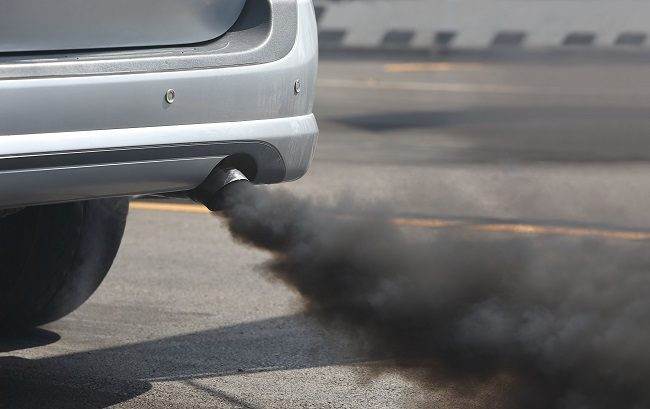
As climate change continues to shape the world around us, governments are taking action. For the everyday car user, this often means problems. Car manufacturers are forced to reduce exhaust gas emissions even more than they have over the past 20 years due to even stricter legislation. Diesel and gasoline manufacturers are doing everything they can to catch up with electric and hybrid cars and comply with new emission standards.
One of the ways conventional fuel-based engines attempt to achieve this is by using Exhaust Gas Recirculation (EGR) systems. The ingenious system helps reduce the amount of nitrous oxide – one of the most harmful byproducts of the combustion process – that comes out of your car’s exhaust. On gasoline engines, the system also reduces fuel consumption when the engine is running at partial load. But what exactly is an EGR system, how does an EGR valve work, and what are common EGR problems? If you’re exhausted from searching for answers to these questions, look no further!
WHAT IS THE EXHAUST GAS RECIRCULATION SYSTEM?
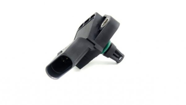
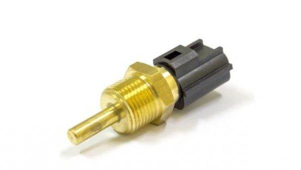
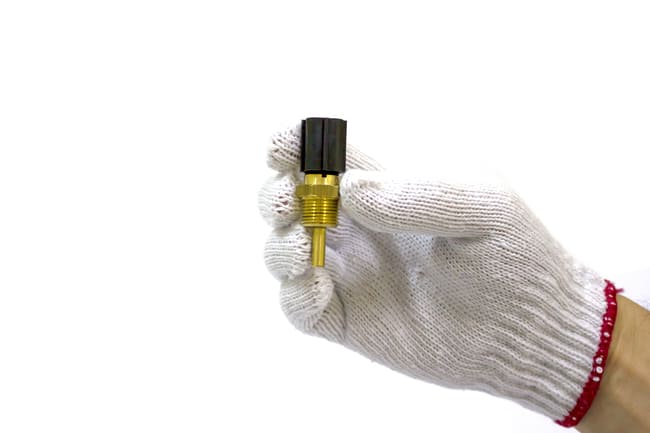
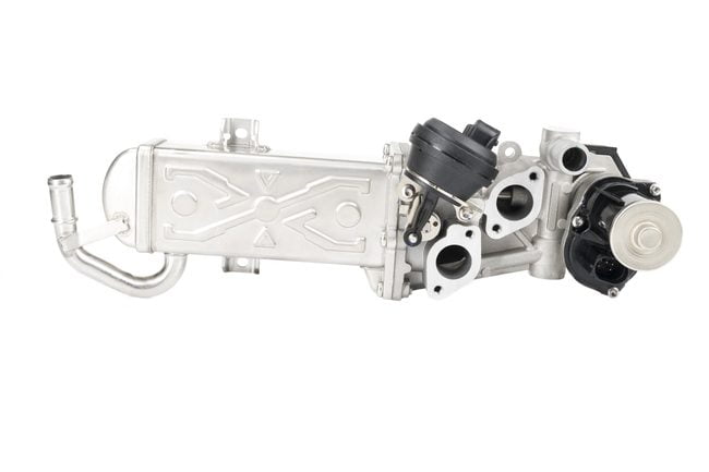
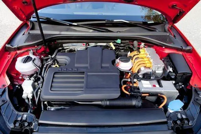
Simply put, the Exhaust Gas Recirculation (EGR) system reduces NOx emissions in internal combustion engines. The system is composed of an EGR valve, a temperature sensor, and a control unit and it is connected to both the ECU and the engine’s intake/exhaust manifolds.
The main goal is to reduce these NOx (nitrous oxide) emissions and it does this by recycling exhaust gases into the combustion chamber, where it cools the combustion. The gases that have already been used in the combustion do not participate in the next combustion process, but they still help reduce NOx as well as the temperature of the chamber itself.
Part of the reason for wanting to keep the chamber temperature low is that if the combustion temperature is high, it can lead to engine overheating and also the production of more nitrogen oxide in the engine’s combustion chamber. The combustion temperature in the combustion chamber is reduced by recirculating some of the exhaust emissions back to the fresh intake air and the lower combustion temperature results in less nitrogen oxide and an engine less likely to overheat.
HOW DOES THE SYSTEM WORK AND WHY DO YOU NEED IT?
As part of the combustion process, air enters the combustion chamber through the intake manifold and mixes with fuel. When it is compressed or ignited (depending on the system), the pressure pushes the piston down to power the engine and the exhaust gases exit through the exhaust manifold. If an engine is running at full load, that is, operating at its greatest capacity, during hard acceleration for example, this process works perfectly and all the oxygen atoms in the air that are sucked in by the intake manifold are used in the combustion process.
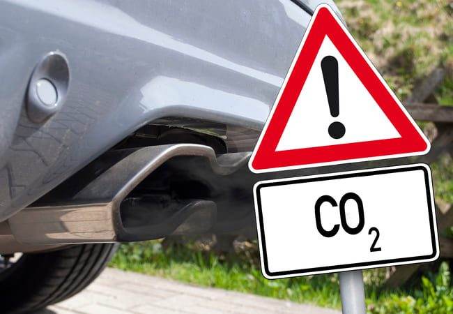
What normally happens is that an engine only runs at partial load. When you are simply driving on the road, idling, or slowly looking for a parking space, the engine is not running at full capacity, which we call a partial load. This becomes a problem regarding emissions. Because less fuel is injected (because the engine doesn’t need to work as hard), not all oxygen atoms are used in the combustion process. The remaining atoms combine with nitrogen (which makes up 70% of the air entering through the intake manifold) to form NOx (nitrous oxide). Unfortunately, this is a toxic air pollutant and it is exactly what the new government legislation aims to prevent. This is where EGR comes in.
In the final exhaust phase of the 4-stroke combustion process, when the exhaust gases leave the cylinder, the exhaust gases are partially rerouted internally and pumped back to the combustion chamber. Before getting there, there is an exhaust gas recirculation valve. The location of the EGR valve depends on your car’s system, but it is always located before the intake manifold so it can regulate the amount of recycled gas.
The gas already used in the combustion combines with the fresh air that is also entering the chamber and the gas that then enters the chamber is a combination of gas already used in the combustion process and fresh air. The valve regulates the amount of this gas allowed.
In collaboration with the ECU, sensors determine the load on the engine, i.e., the power required from the engine, and the amount of exhaust gas that is recirculated is calculated accordingly.
The lower the load, the more exhaust gases are recycled because there will be less fuel injected into the cylinder and thus more harmful NOx byproduct.
If the load is higher, more fresh air and oxygen are admitted and therefore less exhaust gas is recycled. Since the gas that has already been used is inert (it does not react), there is no risk of it reacting with oxygen to produce more emissions.
The temperature of the gas also impacts the combustion process and presents another advantage. Since the exhaust gases are hot, they decrease the time needed for the gas in the cylinder to reach the temperature required to exert pressure on the piston and thus eliminate “ignition delay.” In short, it makes the engine run more efficiently and quickly, providing more controlled combustion.
As mentioned above, this process also decreases the temperature of the combustion process. The compression gases raise the temperature needed to apply pressure to the piston. But the inert gases absorb this temperature because they are at a lower temperature than the compressed gas. The heat is absorbed by the recycled gases and means there are fewer NOx byproducts and less risk of engine overheating.
WHAT ARE SOME COMMON EGR PROBLEMS?
The EGR is used continuously with the engine and the system is therefore subjected to very high loads, which can cause problems, especially on high-mileage vehicles. Since the valve is the most important part of the system here, most problems are associated with it.
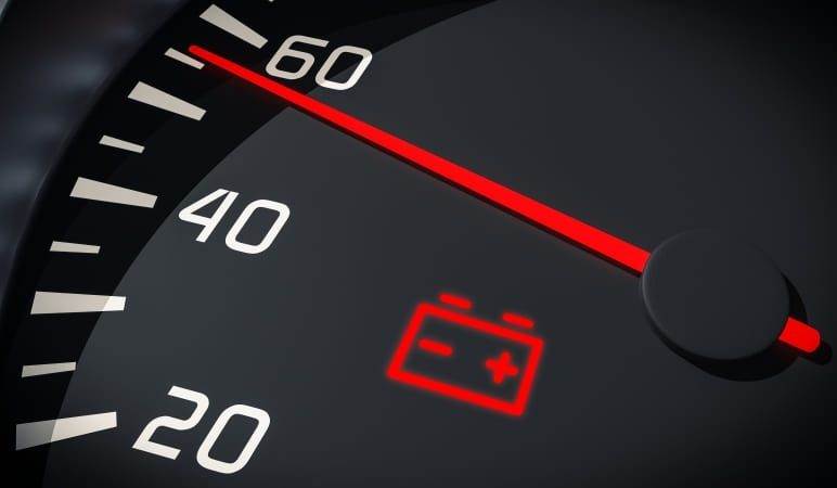
It is quite obvious if there is a problem with your EGR valve because your car will experience bad EGR valve symptoms like rough idling and stuttering during acceleration. Your fuel economy will also decrease due to a faulty EGR valve and you might see a check engine light on the dashboard followed by a readable code in your car’s OBD-II or a newer computer.
The likely causes of these symptoms will be a stuck EGR valve. A buildup of deposits in the EGR valve over a period of time causes the valve to let less or no recycled gas pass through, meaning your car’s performance will start to suffer (the ECU will assume the correct amount of gas for combustion is in there, as it assumes the valve is working). This happens particularly often with a diesel EGR valve. This buildup is part of the vehicle’s normal operation and can be repaired by cleaning or replacing the valve.
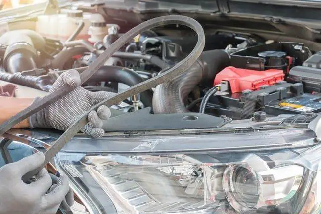
Cleaning the EGR valve is not as complicated as one might think and you can certainly do it yourself. Once you have located and removed your EGR valve (the location varies from vehicle to vehicle, so consult your user manual), shake it gently. If you hear something moving back and forth inside, that’s the diaphragm, meaning there’s a good chance your EGR valve is still in good condition and just needs cleaning to return to normal operation. If you don’t hear anything, your EGR valve might be stuck. This is not a definitive test, but it’s a good starting point.
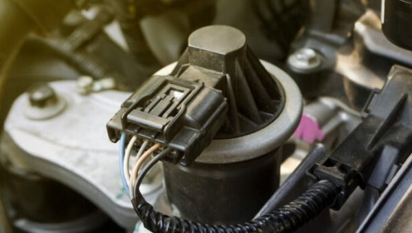
If you have a newer EGR valve, it is likely electronic and therefore a wiring harness is connected to it. In this case, it is important that you avoid applying corrosive cleaners to the wiring and connectors and, of course, the engine must also be off. You will also need reliable eye protection and chemical-resistant gloves.
CLEANING AN EGR VALVE
First remove the vacuum line, which is the rubber hose connected to your EGR valve. If it is brittle, broken, frayed, damaged in any way, or otherwise seems less than perfect, replace it. Vacuum issues are the source of all kinds of engine problems, including a faulty EGR valve.
Then disconnect the electrical harness and unlock the EGR valve. If it doesn’t come off immediately when you have removed the nuts or bolts, you can loosen it by tapping it with wood or a small hammer.
Then remove the gasket and check that it is in good condition and not torn, frayed, or disintegrated. If it doesn’t look so fresh, you can install a new one at the same time.
Cleaning the valve assembly is a two-step process. First, soak the valve itself in a bowl filled with carburetor cleaner. Carburetor cleaner smells horribly bad and is unpleasant, so soak it outside or in a very well-ventilated area. Let it soak overnight if you can. If that’s not possible, move on to the next step.
Important! Remember not to put the electrical part of your EGR valve in the carburetor cleaner!
Once you have let your EGR valve soak in the cleaner overnight (if possible), you need to clean its passages, openings, and surfaces with a small brush. Toothbrushes and pipe cleaners dipped in the same carburetor cleaner you used before are perfect for this. Be sure to use your protective glasses and gloves at this stage to avoid injury. You want to clean the valve as much as possible and get into as many different nooks and crannies as possible – the more black sediment you get out, the better your chances of solving the problem.
Once it is clean and free of crust, you can reinstall your clean EGR valve. Remember to reconnect your vacuum hose and electrical connections if necessary. If you are still experiencing problems after cleaning the valve, you may need to replace it.