Manufacturers have equipped today’s vehicles with sensors for just about every component. But the crankshaft position sensor is one of the first sensors that manufacturers started installing in vehicles, and it’s not hard to understand why.
It’s one of the most essential sensors in your vehicle, and if it goes bad, you can witness significant problems almost immediately.
But what is a crankshaft position sensor and how do you know if you need to replace it? Just keep reading about crankshaft position sensor symptoms and we’ll explain everything you need to know.
What is a Crankshaft Position Sensor?
The crankshaft position sensor does exactly what its name implies; it tracks the position of your engine’s crankshaft. It then transmits this information to the ECU, which uses it to track engine timing and a litany of other functions.
Since your engine’s crankshaft position is directly correlated to the position of each of your engine’s pistons, it’s one of the most useful inputs your computer has to determine when to apply fuel and maximize engine efficiency and timing.
Common Crankshaft Position Sensor Symptoms
Your crankshaft position sensor is essential, which is why you need to know it’s in good working order. Fortunately, there’s not much to watch out for as manufacturers have made these systems fairly self-contained.
But if you experience any of the following symptoms, you need to get your vehicle checked out as soon as possible.
Check Engine Light
This is by far the most common symptom of a faulty crankshaft position sensor. In fact, even if you’re experiencing the other symptoms, you should still see a check engine light. If you’re not, you’re likely experiencing more than one problem, as your vehicle isn’t self-diagnosing properly.
However, just because you have a check engine light doesn’t mean you have a faulty crankshaft position sensor. Check engine lights come on for a litany of different problems, which is why as soon as your check engine light comes on, you should read it to get a clearer picture of what’s going on.
Most parts stores like AutoZone and Advance Auto Parts will check your code for free and offer a printout of the most likely problem.
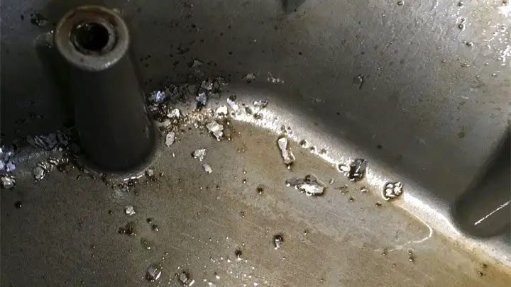
Excessive Engine Vibrations
Your vehicle’s ECU works with the crankshaft position sensor to determine engine timing. If the timing is off, you’ll often experience excessive engine vibrations because the cylinders are firing at the wrong time. Not only can this make your engine shake, but it can also cause significant damage that can end up destroying your engine.
Engine Misfires
It’s all about timing. If your engine is trying to fire in cylinder two while injecting fuel into cylinder four, nothing will happen. Of course, when its four cylinders do fire, you might get double the fuel, leading to all sorts of problems. With a faulty crankshaft position sensor, you’ll likely get an engine that runs terribly.
Sluggish Engine Response
Sometimes the crankshaft position sensor is just a bit slow as it starts to fail. If that’s the case, fuel injection and overall engine timing will be just a step behind. While this will make your engine run terribly, the most important thing you might notice is that you’ll have a sluggish engine response.
But the longer the problem persists, the worse it will get. The longer you wait to replace the sensor, the more likely you are to cause additional damage as well.
Engine Stalling / Backfiring
If your crankshaft position sensor is completely out of whack, you might struggle to keep the engine running. Even if you do get it running, the poor engine performance might assail you with a ton of backfires, and you might even struggle to start it.
If your faulty crankshaft position sensor has reached this point, you need to stop trying to run your engine immediately and replace the component as soon as possible. If you continue to run the vehicle with an excessively faulty crankshaft position sensor, further damage will occur.
Can You Drive with a Faulty Crankshaft Position Sensor?
As a general rule, you can drive short distances with a faulty crankshaft position sensor. However, the longer you drive with a faulty sensor, the more likely you are to cause additional damage. Worse yet, the longer the sensor is broken, the more likely it is to fail completely.
If you have a completely broken crankshaft position sensor, you’ll struggle to keep your vehicle running and further damage will occur.
How Much Does It Cost to Replace a Crankshaft Position Sensor?
When it comes to sensors, crankshaft position sensors are relatively inexpensive. If you’re looking to replace the sensor yourself, you might be able to get one for as little as $50, depending on what you drive. At the other end of the scale, more expensive crankshaft position sensors can cost up to $150.
Meanwhile, if you’re paying for a mechanic to replace the sensor for you, labor costs typically range from $100 to $150. So overall, it will typically cost you between $150 and $300 for a mechanic to replace your crankshaft position sensor and between $50 and $150 if you do it yourself.
How Hard Is It to Replace a Crankshaft Position Sensor?

If you can replace the sensor yourself, you can save over $100, but how hard is it to replace?
In truth, the answer depends on what you drive. Sometimes the sensor is easily accessible, and other times you’ll need to remove several components just to reach it. However, if you can access the sensor, it’s easy to replace. Below is a step-by-step guide to replacing the sensor yourself and saving $100.
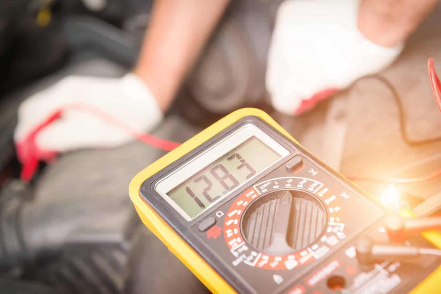
1. Disconnect the Battery
Before handling any electrical components of your vehicle, you need to disconnect the battery. This is because your vehicle has tons of electrical components. As soon as you start plugging and unplugging components, the risk of a power surge from static electricity on different systems always exists.
A quick electrical surge can cost you hundreds of dollars. Play it safe and disconnect the negative battery terminal and let it sit for at least 10 minutes before continuing.
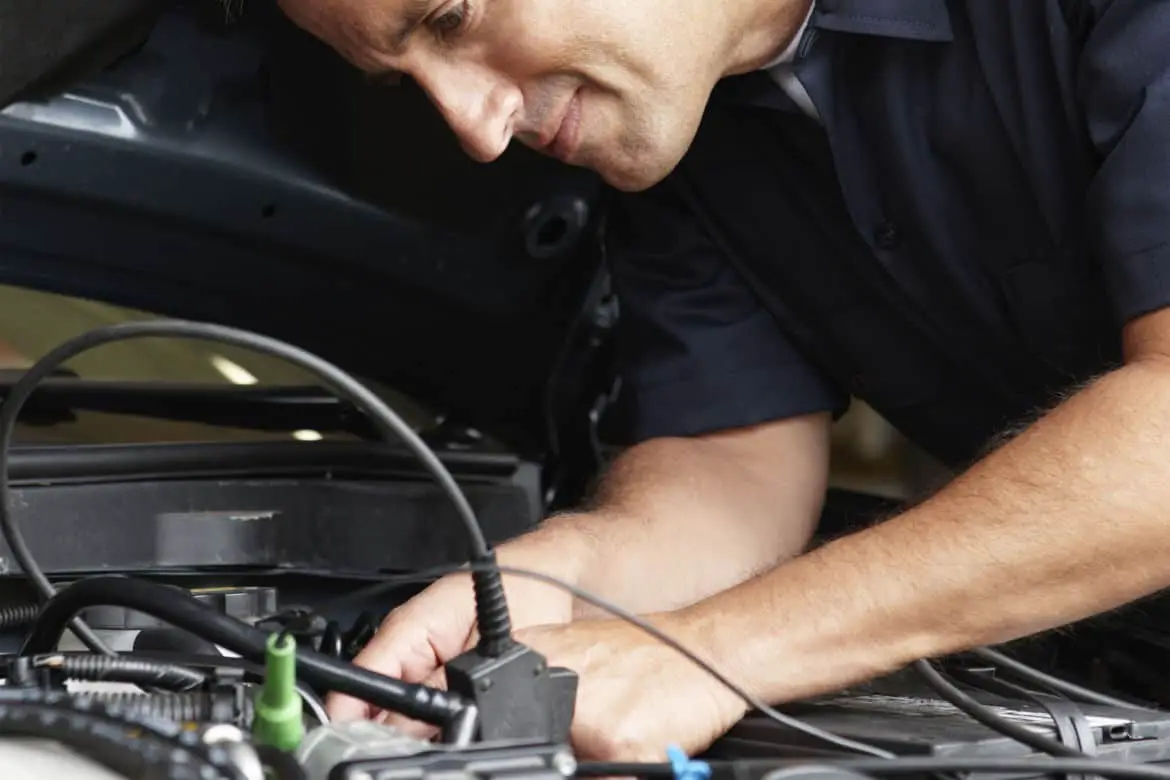
2. Locate the Sensor
If you haven’t located the sensor yet, now is the time to do so. It will be located towards the bottom of your engine. If you can’t find it, a quick Google search should highlight its position for you. It might not be easy to reach and you might need to remove several other components to access it, but the less you remove, the better.
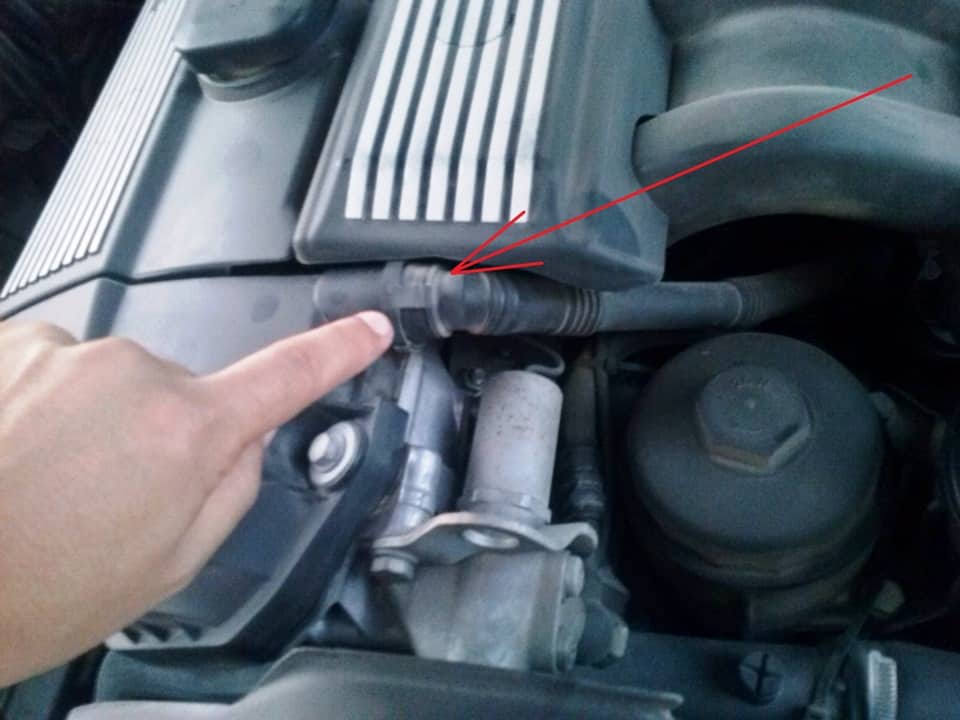
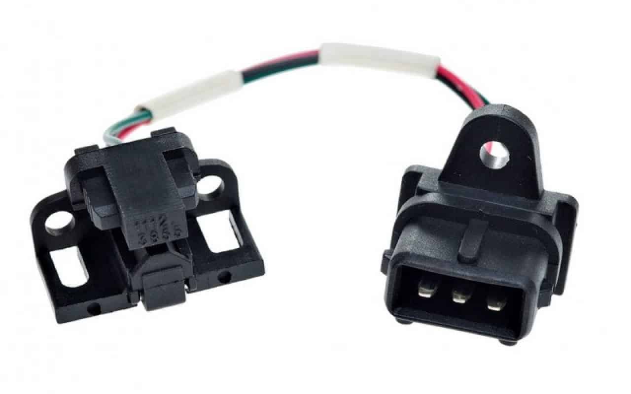
3. Unplug the Electrical Connector
Crankshaft position sensors have quick-disconnect electrical connectors that power them. Disconnect the wiring by releasing the pull tab and gently pulling on the connector. Make sure not to pull on the wiring as you don’t want to cause additional damage.
4. Remove the Mounting Bolt
Once you’ve disconnected the electrical connector, you’ll need to remove the mounting bolt holding the sensor against the engine. Typically, it’s just a single bolt and the exact size varies from manufacturer to manufacturer. It’s not uncommon to see mounting bolts that also use Torx bits or hex head sockets.
5. Remove the Sensor
Once you’ve removed the mounting bolt, you can gently remove the sensor. Corrosion and rust might have stuck it in place; if that’s the case, you’ll need to twist the sensor while pulling to remove it.
6. Install the New Sensor
Once the old sensor is out, it’s time to install the new one! Make sure the mounting bolt aligns after installing the sensor. Otherwise, you’ll need to remove the sensor again to install it properly.
7. Reattach the Electrical Connector
Once you’ve installed the mounting bolt, it’s time to reconnect the power. Plug in the electrical connector; you should hear it click into place. If you don’t hear the click, try gently removing the connector. If it’s locked in place and you can’t remove it without pulling the release tab, then you’re good to go!
8. Reconnect the Battery
The final step is to reconnect the battery. Since you disconnected the battery, you’ve already reset the entire system and you should be ready to go! Simply start your engine and see if the check engine light is off. If it is, you’ve fixed the problem. If not, the sensor wasn’t your problem to begin with.
Summary

With modern cars, it’s easy to feel like there are too many sensors and electrical components. While it might feel like that in the heat of the moment because things aren’t working properly, the truth is that sensors have improved our vehicles in multiple ways.
And while it can be frustrating to replace small electrical components, they are much easier to replace, even for the least mechanically inclined individuals, than trying to manually time an engine yourself.