There’s nothing as welcome as the cool breeze from a vehicle’s air conditioning in the midst of summer heat. After all, without these modern conveniences, our daily commutes would be much less bearable, no matter their length. This notion, in itself, places greater importance on the condition of our vehicle’s air conditioning system as a whole.
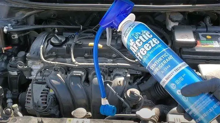
As most drivers well know, a vehicle’s air conditioning system must be properly charged to achieve the highest degree of operational efficiency. For this reason, it’s important to periodically recharge a vehicle’s air conditioning system, especially if there is a leak of any severity in the system. The charging can be done using DIY kits or can be performed by a professional.
However, many often wonder if their vehicle’s air conditioning system is overcharged, especially if they have refilled it themselves. It’s also natural to contemplate the outcomes of such overcharging, as well as the symptoms that such a condition might present.
Read on to learn more about the various symptoms associated with an overcharged air conditioning system, as well as how to resolve such an issue, should it arise in the future.
What Does an “Overcharged” Air Conditioner Mean?
Every air conditioning system ever assembled has a maximum charge rate, and those found in today’s vehicles are no different. This “maximum charge” details the total refrigerant capacity that a particular system can accept.
Based on this knowledge, the idea of system overcharging is quite simple. An overcharged condition exists in an air conditioning system whenever an excessive amount of refrigerant has been introduced, which typically equates to a total system charge exceeding that specified by the system’s manufacturer.
Whenever an air conditioning system is charged beyond its capacity, a number of troubling symptoms can occur, most of which are detailed below. However, suffice it to say that an overcharged air conditioning system is largely incapable of operating at its peak efficiency, to the great dismay of any driver who depends on its functionality for their comfort.
How Does It Happen?
Air conditioning system overcharging typically occurs whenever a vehicle owner attempts to charge the system in question themselves, using basic recharge kits that can be purchased at any auto parts store.
When using a kit of this nature, many find themselves limited in their ability to accurately measure the amount of refrigerant being introduced. Furthermore, some kits come with few viable instructions.
Additionally, most DIY A/C charging kits only come with a single gauge, intended to display readings in a system’s low-pressure circuit. In this case, no high-pressure reading is obtained, limiting the ability to fully observe a system’s response to one’s charging efforts.
Most often, a driver is unaware that they have overcharged their vehicle’s air conditioning system until undesirable cooling is noticed. Moreover, a number of additional symptoms can also occur, leading one to wonder whether or not they have overcharged the system as a whole.
Overcharged AC Symptoms
The presence of too much freon in a vehicle’s air conditioning system is often accompanied by a host of secondary symptoms. Recognizing these symptoms can prove helpful when attempting to quickly remedy the current situation.
Here are some of the most common symptoms associated with air conditioning system overcharging.
#1 – Warm Discharge Air
An overcharged air conditioning system rarely cools as it should, often blowing warm air from the system’s vents. If you have recently refilled your vehicle’s refrigerant but are getting no relief from the heat, an overcharge of refrigerant might be to blame.
#2 – Odd Noises
If you have just had your vehicle’s air conditioning serviced and now notice strange noises coming from under the vehicle’s hood, it might be wise to have the system’s refrigerant charge checked again.
System overcharging can cause an air conditioning compressor to struggle, often resulting in an audible gurgling or whining sound.
#3 – Irregular Pressures
Overcharging an air conditioning system often causes system pressures on the high side to skyrocket. System overheating can also result, adding further insult to injury and preventing any level of cooling from being achieved.
#4 – Freezing of the Suction Line
Freezing of a system’s suction line can easily occur in the event of a slight overcharge. This primarily happens when the heat load in the evaporator is rather minimal and system freezing temperatures are reached.
What To Do
In all cases, the issue of a vehicle’s air conditioning system overcharging must be resolved promptly. A vehicle owner’s failure to act can quickly lead to serious and irreversible damage to components. This, in turn, can require additional expense on the part of the driver to restore the system’s full functionality.
In short, one must purge their vehicle’s air conditioning system to achieve the desired charge rate. Unfortunately, this will almost certainly require a trip to the local service center, as most do not have a refrigerant recovery machine available at home.
Venting refrigerant into the atmosphere is highly illegal, as freon is recognized by the EPA as an environmental pollutant.
If you are unsure whether your vehicle’s air conditioning system has been overcharged or not, a trip to your local automotive service center is highly advised. It is far better to address the issue in a timely manner than to suffer a system failure due to complacency.
Can Overcharging Damage the A/C Compressor?
Overcharging a vehicle’s air conditioning system can prove detrimental, if not catastrophic, to the system’s compressor. This stems from the fact that a compressor is subjected to a significantly increased load under such conditions, thereby causing significant fatigue.
Furthermore, extreme overcharging can lead to compressor slugging, which describes a condition where liquid refrigerant enters the intake side of a compressor, often with devastating consequences.
Significant damage to a vehicle’s air conditioning compressor not only requires replacement but also a complete system overhaul. This is due to the high likelihood of system contamination when debris from a failing compressor is forced downstream. In any case, damage of this nature is quite costly to repair.
Different Types of Superchargers (and How They Work)
Internal combustion engines, as you well know, need fuel and air to operate. Fuel is stored in the fuel tank and must be replenished regularly. Air is abundantly supplied by the atmosphere around us and reaches us at sea level pressure of 14.7 lb/in².
This works very well, but that’s all the pressure you’ll get to push air into your engine. You’ll get even less (accompanied by equally reduced power) when climbing the Continental Divide over a high mountain pass in one of the many Western states.
If only we could increase this pressure. If only we could cram more air into our vehicle’s engine along with more fuel. Ahhh. . . the supercharger. These remarkable devices can compress more air into your car’s engine intake system and, with the right amount of fuel, will thus increase engine power by 50 to 75 percent.
What is a supercharger? How did the supercharger (sometimes called a blower or compressor) come about? How many types of superchargers are there? Let’s answer these questions.
What Is a Supercharger?
A supercharger is a device powered by an engine (or an electric motor) that increases the airflow to the engine, thereby increasing that engine’s power. Since the early stages of internal combustion engine development for powering automobiles, trucks, and yes, airplanes, superchargers have been part of the story.
The reason is quite obvious. Supercharging is a relatively simple way to significantly increase the power of almost any internal combustion engine design, whether they are two-stroke or four-stroke, gasoline or diesel. What practical engineer or enthusiastic car owner could resist such a temptation?
Let’s take a look at the types of superchargers, how they came about, and how they work to greatly increase airflow to an engine.
Types of Superchargers
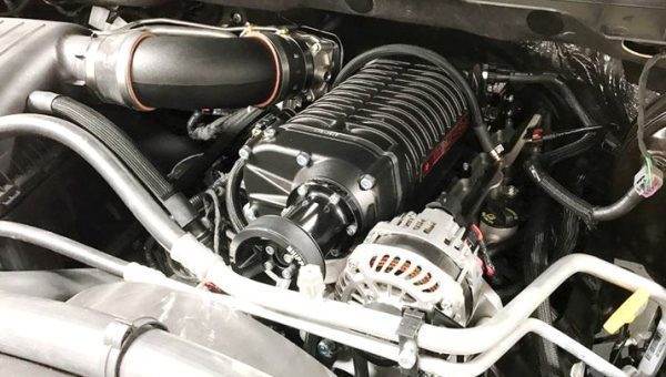
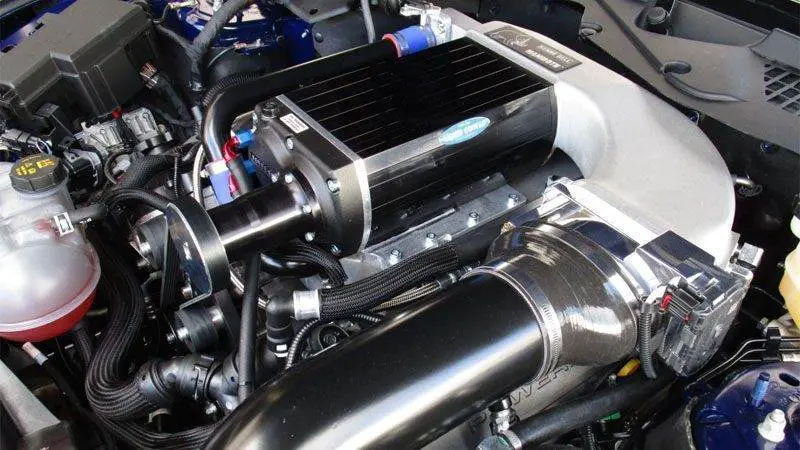
#1 – Roots Blower
Roots-type supercharger on a 2017 Mustang GT (Credit)
Let’s go back in history to a time when most people’s means of transportation required large four-legged animals for power. In 1860, the Roots brothers designed and patented a mechanical ventilation device intended for blast furnaces and several other applications. This was one of the first attempts to build a relatively efficient positive displacement blower.
It used two meshing three-lobed rotors mounted on a parallel shaft. It proved very effective at moving large volumes of air.
The Roots blower progressed rapidly and first appeared in an engine design patented by Gottlieb Daimler around 1885. Its use in production automobiles first occurred around 1921 with German luxury cars manufactured by Mercedes.
These early superchargers proved capable of adding up to 30 to 40% increase in engine power with few other changes to the engines of that era.
Daimler’s designs quickly became popular for street and racing vehicles. Mercedes, Alfa Romeo, and Bugatti come to mind for racing successes using this technology.
The Roots blower design was improved by General Motors (Detroit Diesel) primarily for two-stroke diesel truck engines in the late 1930s. These blowers were later often applied to automobile racing engines.
Such applications are still widespread today. At the drag strip, for example, it’s common to see dragsters using Roots-type superchargers perched on huge engines.
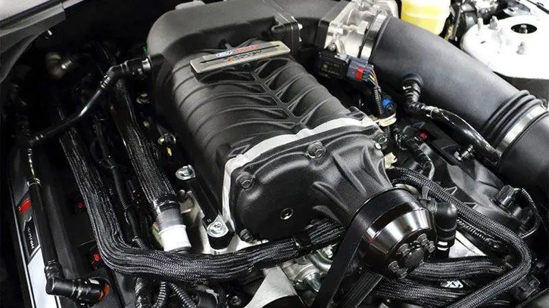
#2 – Screw Compressor
Twin-screw supercharger in a 2015 Mustang GT (credit)
Following the path laid out by the Roots brothers, in 1878, German designer Heinrich Krigar patented the screw compressor. Similar to the Roots blower, it used two parallel shafts but was capable of producing a much higher pressure increase due to the screw shape of its rotors.
However, manufacturing complexity delayed its widespread industrial and automotive use for several decades.
A Swedish engineer, Alf Lysholm, in the mid-1930s, brought key manufacturing technologies that reduced the cost of the screw design. This type of compressor quickly found a niche in the air conditioning world and in other industries where highly efficient high-pressure outputs were required.
In the automotive world, screw compressors are sometimes referred to today as twin-screw superchargers.
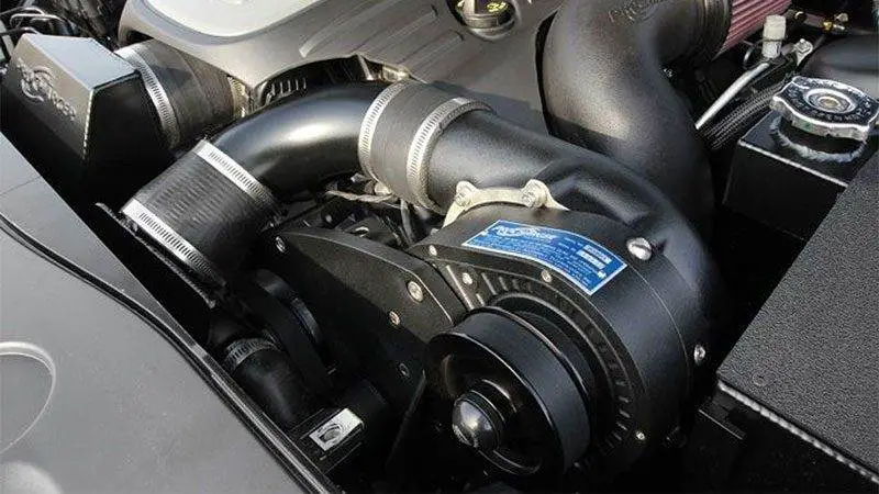
#3 – Centrifugal Supercharger
Centrifugal supercharger in a 2012 Dodge Challenger R/T (Credit)
The third type of supercharger is the centrifugal. In the early 1900s, French designer Louis Renault patented the first centrifugal supercharger for automotive use. Within about three years, American race car builder Lee Chadwick took Renault’s design, stacked three stages (three rotors), and began a successful career racing powerful hill climb race cars.
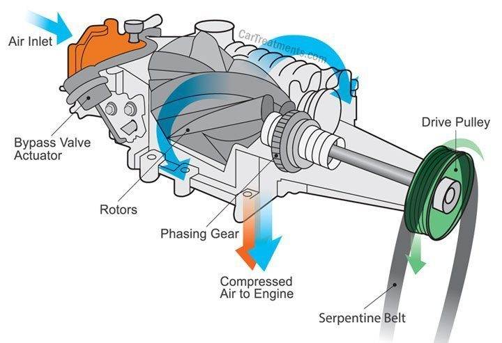
Today’s centrifugal superchargers use only a single impeller with complex curved blades mounted inside a volute-shaped housing. Air enters the impeller near the center of the housing. The rotating impeller slings it to the outer passage of the housing while increasing the air’s velocity.
The air is then routed through a diffuser of increasing diameter which slows the flow and increases the pressure. This high-pressure air is then forced through the induction system to the engine.
A major advantage of this type of supercharger is its relative simplicity. It essentially has one moving part, the impeller. The impeller spins inside a housing with relatively large clearances, making its manufacturing cost reasonably low.
All these types of superchargers are directly driven by the engine. Using a gear drive system or a much simpler belt drive allows the supercharger speed and thus the boost to increase proportionally with the engine’s rising speed.
The output pressure to the engine can vary according to the driver’s power needs through the use of a bypass valve that opens when excess boost pressure needs to be vented. The airflow outputs of these superchargers are modulated in concert with the fuel injection flow by the vehicle’s Powertrain Control Module (PCM).
Production automobiles that have benefited from supercharging technology include historic Studebakers from the early 50s using Paxton blowers, Ford Shelby Mustangs, and popular front-engine Dodge automobiles.
Using compact screw superchargers, some of the Dodge street vehicles easily produce over 800 BHP. A careful right foot is in order with one of these amazing cars.
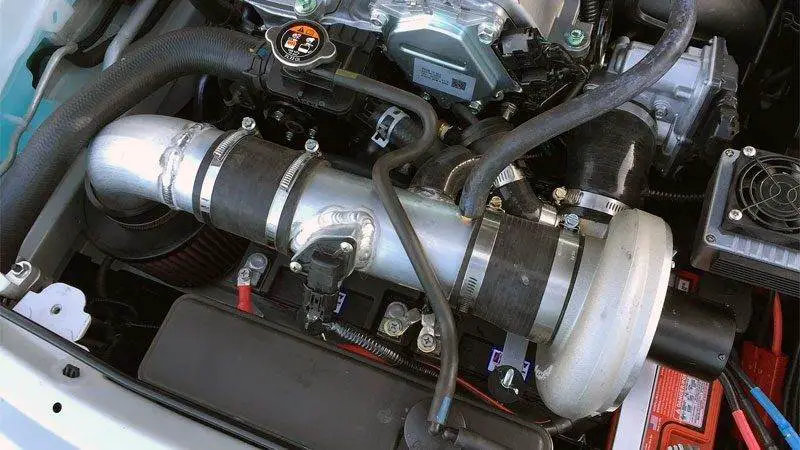
#4 – Electrically Driven Supercharger
Electric supercharger on the 2017 Mazda Miata (Credit)
A fourth type of supercharger making its appearance is electrically driven. Each of the three blower configurations described above can be driven by a highly efficient permanent magnet DC motor. This arrangement allows supercharger speeds to be continuously adjusted to the engine’s air needs by the vehicle’s PCM.
An electric motor to spin the internal parts of the supercharger is a much simpler drive system than the complex belts or gears used in mechanical drives. This could potentially be a cost reduction and a reliability improvement over older mechanically driven superchargers.
How Supercharging Benefitted the Aircraft Industry
Although costly in dollars and tragic in terms of horrible human losses, wars have been the testing ground for many technological advances. This is also true with supercharging.
World War II saw the growing need for aircraft capable of reaching high altitudes. Normally aspirated piston-engine aircraft could not operate effectively in the thin air well above 20,000 feet.
Superchargers became common in these wartime fighters and bombers allowing altitudes up to 50,000 feet. With such altitudes, the speed and range of aircraft were also greatly improved.
The Engines Beneath the Superchargers
Supercharging can increase combustion pressures and power outputs of many different engine types. These pressure and power increases will always be accompanied by significantly higher engine temperatures and internal structural loads.
Designers had to compensate for this with improved engine cooling and lubrication, improved metallurgy for engine blocks and internal parts as well as higher quality fuels. These technological advancements have been passed down to the cars and trucks we drive today.
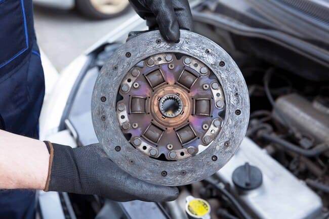
Why the clutch slips
Does it seem like your vehicle is accelerating slower than usual and struggling to climb hills? Don’t rush to look for ignition or fuel supply faults: if these symptoms are accompanied by free play in the clutch pedal and an unpleasant burning smell is occasionally noticeable inside the cabin, the problem is likely clutch slipping. We will explain why this happens and how to avoid it.
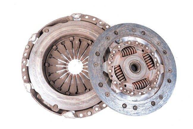
CLUTCH SLIPPING: WHERE THE PROBLEM IS
The proper functioning of the system depends on the friction force between the driven disc and the flywheel. If the friction coefficient decreases for any reason, the contact surfaces begin to slip, and the torque is not fully transmitted from the engine to the transmission. As a result, accelerating the vehicle to a certain speed takes more time, and its performance deteriorates. It also becomes more difficult to tackle inclines and hills because the power transmitted to the gearbox shaft is insufficient to move the vehicle.
5 MOST COMMON REASONS FOR CLUTCH SLIPPING
Worn and damaged friction linings and disc surface. Excessively worn friction linings, due to reduced thickness, are not sufficiently pressed against the flywheel surface. The compression force of the mechanism is not enough to ensure a fixed connection of its elements. A deformed lining is pressed unevenly against the flywheel.
Oiling of friction linings. It contributes to reducing their roughness. Due to the low friction coefficient, the contact elements slip.
Weakened or damaged diaphragm spring. If the spring’s elasticity has decreased, the pressure exerted on the driven disc when pressing the pedal will be insufficient to activate the unit.
Malfunction of the clutch linkage. A stretched cable, a damaged fork on vehicles with mechanical clutches, swelling of rubber components, or loss of seal integrity on vehicles with hydraulic control can also lead to clutch slipping, as the pressure force on the diaphragm is not sufficient to ensure fixed contact of the coupling parts.
Damaged wear compensation mechanism. Due to a malfunction of the adjustment ring or sensor spring, adjusting the free play becomes impossible. This reduces the holding pressure of the driven disc.
6 RECOMMENDATIONS THAT WILL HELP AVOID CLUTCH SLIPPING
Try to replace system components as a kit. The average lifespan of the pressure plate and driven disc, diaphragm spring, and release bearing is roughly the same, about 100,000 to 150,000 kilometers. Therefore, to ensure the system operates as long as possible, always replace components as a kit.
Check the tightness of vehicle components and assemblies. Poor quality or damaged seals of the engine and transmission, oil leaks from the input shaft oil seal or crankshaft seal, loss of seal integrity in the hydraulic actuator are reasons for oiling the friction linings.
Choose components according to your driving style. A standard clutch with composite material friction linings is suitable for calm and smooth driving. They have the optimal friction coefficient, low operating temperature, and are inexpensive. However, a sports car is better equipped with a special clutch designed for heavy loads. Its linings are made of materials with added carbon and Kevlar, and a mixture of copper, aluminum, cast iron, and ceramic. It withstands much higher temperatures, has increased wear resistance, and is suitable for aggressive driving.
Check the proper adjustment of the pedal travel. Insufficient pedal travel prevents complete disengagement of the clutch. This causes accelerated wear of the friction linings and can lead to overheating and warping of the driven disc.
Always use the working fluid recommended by the manufacturer. Do not mix fluids of different compositions. Aggressive compounds formed as a result of mixing or components contained in a particular class of fluids can be destructive to the hydraulic clutch actuator.
Follow these clutch operation rules:
When starting, first release pressure on the pedal so that the car starts and begins to move slowly, then hold it in a semi-pressed state for 2-3 seconds, then release it completely;
Do not start at high engine speeds;
When descending a steep slope, engage first gear, occasionally pressing the brake pedal to avoid overheating the components.
When exiting difficult off-road areas, such as a puddle, a pile of snow, or mud, use a tow if possible;
While driving, do not rest your foot on the clutch pedal continuously to avoid unintentionally pressing it;
Do not overload your vehicle, especially when driving on poor-quality roads: this significantly increases the load on the assembly.
CONCLUSION
Clutch slipping is a common failure, making driving not only uncomfortable but also dangerous. But in most cases, any car owner can prevent problems. Simply purchase high-quality components and follow the above recommendations.
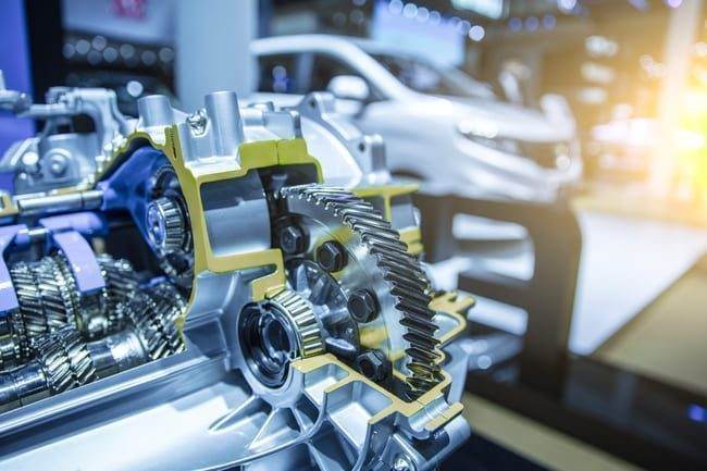
Signs of Transmission Problems and How to Fix Them
Automotive transmission systems are complex networks of moving parts that interact to transfer the right amount of power from the engine to the wheels with maximum efficiency. They allow for changing the gear ratio between the engine and the drive wheels when the vehicle accelerates or decelerates. The car’s gears are essential because without them, the engine’s RPM would be uncontrollable, leading to the destruction of the unit. These parts are constantly subjected to extreme temperatures and pressures; therefore, regular maintenance is essential to keep your car on the road. Significant damage can not only cost you your savings but also your safety. It is important to know the symptoms of a failing transmission to avoid further damage.
SIGNS OF TRANSMISSION PROBLEMS
!Unresponsiveness. If there is a delayed response or none at all when you shift gears, this is likely due to a system failure. If you own a manual car, you may notice a significant difference between the engine RPM and the car’s actual speed.
!A burning smell. This could be an indicator that the automatic transmission fluid (ATF) is low or has deteriorated and is overheating, contributing to premature engine wear and corrosion. It must be changed regularly for everything to function properly.
!Fluid leaks. If you spot a puddle of smelly red fluid or muddy brown fluid under your vehicle, the ATF might be leaking. The leak will need to be repaired first, then new fluid added.
!Strange sounds. Knocking, whining, or humming noises are classic symptoms of problems like these, especially if you hear them when shifting gears. It is advisable to contact a professional mechanic as soon as possible for a proper diagnosis.
!Grinding or shaking. For example, you might notice a grinding noise coming from the gears or the vehicle may start to shake during gear changes.
!A dragging clutch. This is only a symptom for manual vehicles. It indicates that the clutch disc and flywheel are not disengaging properly when the clutch pedal is pressed. This can be caused by a faulty clutch cable or mechanism.
!Slipping gears. This is a serious safety hazard for all road users and it is recommended to have the issue addressed immediately by a professional. Common causes include a lack of fluid and worn bands or gear components.
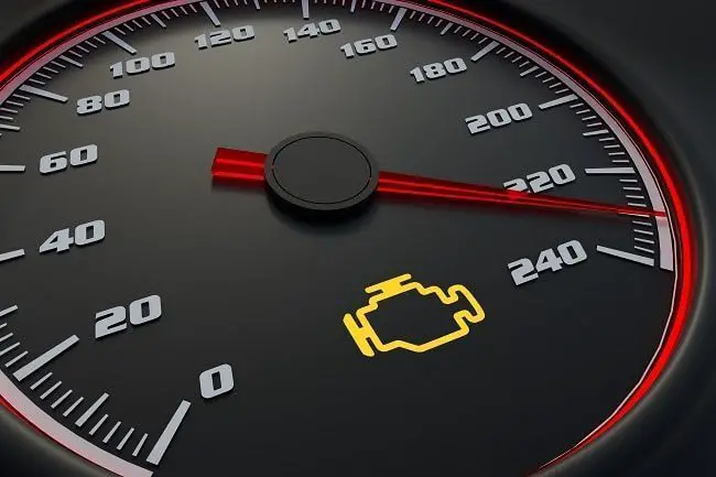
!The check engine light is on. This warning could have been triggered for several reasons. The problem can be identified by performing a diagnostic scan.
HOW TO CHECK THE TRANSMISSION SYSTEM
How to perform a diagnostic scan:
If the check engine light comes on, it would be wise to scan the system and decipher the diagnostic trouble codes (DTCs). You can do this using an OBD2 scanner. The device should help you determine operating factors such as temperature and transmission inputs and outputs.
You will first need to locate the data link connector, which is usually located under the dashboard on the driver’s side. After turning off the vehicle, plug the diagnostic tool in using the connector.
Once you have done that, turn on the vehicle and wait for the scanner to start up. You may need to turn it on using the power button. When the device is ready to use, you can click the scan button and follow the on-screen instructions. It will display a number of DTCs that indicate the problems detected by the onboard computer.
Read the diagnosis carefully. You can look up the codes in the manual or online to decipher them.
Checking automatic transmission fluid:
You can check the fluid level using a dipstick similar to the one used for oil. Many problems can be related to fluid levels and if there is not enough ATF, there is probably a leak. On the other hand, overfilling the reservoir can cause the fluid to foam, which puts more pressure on the components.
Before checking the reservoir, make sure the car is parked on a level surface. Run the engine for a few minutes so that the fluid is warm enough. Most manufacturers will allow you to keep the engine running for this process.
Caution: Engine components and fluids will be hot, handle them with care.
You can now remove the dipstick and clean it using a clean, lint-free cloth. Then put it back into the reservoir and remove it again to measure the fluid level. The marks on the stick will indicate if the ATF is low or if the reservoir is full.
You should also check the color of the ATF. If it is clear and clean, it is still good to use. If it is black or brown, it is probably burnt and contaminated.
It is best to have manual fluid checked by a technician as it can be difficult to access and most manual vehicles do not have a dipstick for it.
RECOMMENDED REPAIRS AND TIPS
Transmission systems can be repaired, rebuilt, or completely replaced depending on the extent of the damage and the most cost-effective solution. If the situation is chronic or multiple failures have occurred, the best option may be to pay a technician to rebuild the transmission. This is a comprehensive process that involves disassembling the entire system, inspecting and replacing or repairing components before cleaning and reassembling them. This way, you will have a complete overview of the situation and hidden defects can be detected. However, it is not cheap as it is a labor-intensive process.
Leaks are usually caused by cracks in the lines, broken seals, a damaged pan gasket, or a faulty torque converter. It is possible to repair leaks yourself, if you have the tools, skills, and experience to do the job. The fluid will need to be drained first before you can replace components and change gaskets and seals.
Different manufacturers will recommend different intervals, however, the general recommendation for manual vehicles is to replace the fluid every 30,000 to 60,000 miles. ATF can last up to 100,000 miles. Driving conditions and the loads borne by the vehicle should also be taken into account, as this can influence the fluid aging process. You should also ensure that you are using the correct product, in accordance with the manufacturer’s instructions.
Your car is losing coolant but there’s no leak
Coolant, also known as radiator fluid and antifreeze, is vital for the hydration of the cooling system and the vehicle. Mechanical failures of the cooling system are one of the main reasons why cars break down on highways. Checking its level and condition is part of regular vehicle maintenance. Generally, there should be a leak somewhere if the vehicle loses a large amount of antifreeze. However, a car can lose coolant without a leak. What should you do when the coolant disappears from the reservoir without leaving a trace?
Coolant Loss But No Leak: Where Is My Coolant Going?
It might seem ghostly if you think about coolant loss with no visible leak. But, things are not as complicated as they seem. A poorly maintained antifreeze system, faulty components, or a rapid change in driving style can contribute to the disappearance of this coolant.
These parts could be the cause when the antifreeze level drops without any visible leak:
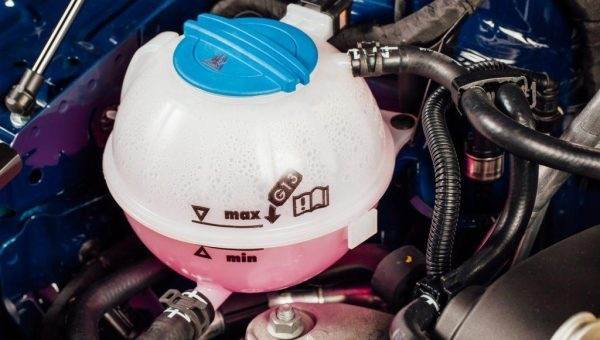
Overfilled Cooling System
Overfilling the system could be the reason for the mysterious disappearance. You must maintain the fluid at the required level. A COLD/MIN label on the reservoir indicates the ideal antifreeze level when the engine is cold. The coolant in the radiator should be just below the filler neck.
An Internal Puncture
When you lose coolant but no leak is visible, several parts could be to blame. It could be a blown head gasket, a fractured cylinder head, damaged cylinder bores, or a manifold leak. It could also be a hydraulic lock.
If the antifreeze disappears without an apparent reason, check that these components are not cracked, damaged, or faulty. Any of these issues can destroy the engine if they last too long. However, you can breathe easy if the mechanic finds no trace of exhaust gases in the coolant. This means the fluid has not yet reached the engine.
A Worn Radiator Cap
The radiator cap can deteriorate over time, allowing antifreeze to pass through when you’re driving. A clogged radiator system can also be a problem because it blocks the flow of the fluid. Check the radiator when the coolant disappears without any trace.
Replace the worn radiator cap.
Overheated Engine
Engine overheating and coolant are closely related. Loss of fluid can lead to an overheating condition, but overheating can also contribute to coolant loss. Simply fill the reservoir to the maximum limit and monitor the engine’s condition and the rate of coolant usage.
Using a temperature gauge will tell you whether the engine is heating up more than usual or not. If it is, take the car to a mechanic to find out the causes of the overheating. Fixing the problem will restore the normal cycle of coolant consumption.
Some other things that can cause coolant loss but no leak are driving uphill, carrying heavy loads, a faulty exhaust gas recirculation (EGR) system, and a worn water pump.
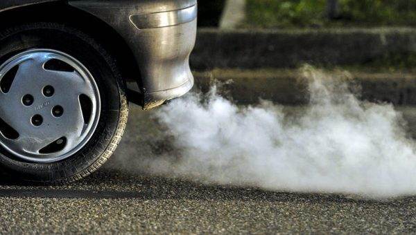
White Exhaust Smoke: Main Causes and How to Fix It
You never want to see smoke coming from your car’s exhaust pipe. In most cases, a thin white smoke from your exhaust in winter is perfectly normal and not a cause for concern. However, whenever you notice thick puffs of white exhaust smoke, it’s a sign that something is wrong with various components of your engine, whether it’s white exhaust smoke at startup or white exhaust smoke during acceleration.
The most common reasons for thick white exhaust smoke involve a malfunction that requires immediate repairs or replacement of faulty parts, many of which are very expensive, and if you continue driving in this condition, you risk further damage to your vehicle’s engine. To avoid this, you need to understand the different root causes of white exhaust smoke and master the maintenance steps to troubleshoot and resolve these issues. The cost of repair or replacement is also included in each case.
Exhaust Emissions: What is Normal?
Before continuing to explain why thick white exhaust smoke is a sign of problems, you must first understand where exhaust gases come from and what is normal. Inside your engine’s combustion chamber, a spark ignites the fuel and air mixture, creating a series of contained combustions or explosions inside the cylinder. The direct byproducts of these explosions are the exhaust gases that are routed to the exhaust system. Before exiting through your tailpipe, these gases pass through the muffler to reduce noise and a catalytic converter to reduce harmful emissions.
Under normal conditions, you should not see exhaust coming out of your tailpipe. Especially in winter, however, you might sometimes see a thin veil of white-colored smoke, which is just water vapor. This is perfectly normal and would disappear after a short while. It is important to understand that even though thin white smoke from the exhaust is normal, if it is thick and comes out in visible bursts, you will need to perform an inspection of various parts to diagnose the source of the problem.
What Does White Exhaust Smoke Mean?
Thick white smoke from the exhaust suggests that coolant or water has inadvertently entered the combustion chamber, which they should never do. When coolant or water is burned in the engine block, it produces thick white smoke that comes out of your tailpipe.
A common phenomenon is white exhaust smoke emitted in thick bursts. Never ignore it and let it persist. The most common reasons for this event include cracks on vital engine parts, including damage in the cylinder head, head gasket, or engine blocks. Even if it’s just a small crack, the damage can easily worsen if you continue driving and delay replacing the cracked component. This could lead to further contamination of the engine oil or engine overheating, which can result in permanent engine damage. You would then need to replace the completely failed engine, which is expensive and a job best left to professionals.
What does white exhaust smoke mean? Below are the 9 most common reasons for white exhaust smoke, and further down, how to troubleshoot and handle each culprit.
Reasons for White Exhaust Smoke
Thin White Smoke: Condensation Buildup
Thin white smoke at startup that disappears then is usually the result of condensation buildup in the exhaust system. It tends to occur in winter or on cold mornings. The smoke should be thin, not too visible, and only come out in small quantities at startup, and will die out fairly quickly after your engine warms up, especially after about 30 seconds to a minute. This is not a sign of a problem, but if it occurs in conjunction with other instances of reduced engine performance or hard starting, it could indicate a more serious problem within your engine.
Coolant Leak: Damaged Coolant Reservoir
Sometimes, if the coolant reservoir tank is damaged or cracked, there can be a coolant leak into the engine’s combustion chamber. This leaking coolant is then burned in the cylinders, creating thick white smoke from the exhaust.
Coolant leaking from a cracked coolant reservoir is usually less common than the leak sources just below, but it can happen when you are fixing another issue nearby and accidentally damage the reservoir. In any case, you will need to replace the damaged reservoir.
Coolant Leak: Crack in the Cylinder Head, Engine Block, or Head Gasket
Although a cracked coolant reservoir is rare, when most mechanics hear about thick white smoke from the exhaust, they would assume the worst. This is usually due to a crack in the cylinder head, head gasket, or engine block, none of which are very quick or cheap to replace, and are not a maintenance job for a novice.
Cracks in these parts are caused by an engine constantly overheating due to low coolant levels, which is due to a coolant leak and constant engine temperature fluctuations. They allow coolant or oil to seep into the cylinders, which are then burned and produce thick white exhaust smoke.
Cracked Cylinder Head
Whenever your cylinder head is cracked or damaged in any way, coolant leaks from it and mixes with the engine oil. Once this happens, the oil will be contaminated. This doesn’t need to be a large crack; just a small crack is enough to create thick puffs of white smoke from your tailpipe. As the coolant continues to mix with the engine oil, the white smoke will start to have a distinct sweet smell that won’t go away.
Cracked Head Gasket
The head gasket is a thin sheet of metal located between the cylinder head and the block, sandwiching the top and bottom of most engines. Its main function is to form a seal between the two parts and helps prevent coolant leaks from the hood surrounding the engine.
Normal wear and tear is one of the reasons why cracks form on the head gasket. When this happens, coolant is no longer contained in the engine’s cooling channels but ends up in the cylinder, where it is burned. A cracked head gasket cannot be repaired; it will need to be replaced right away.
Cracked Engine Block
The worst-case scenario is that your entire engine block is cracked. If this is indeed the culprit, prepare for an expensive and lengthy replacement. You would probably need professional service in this case.
Most engine blocks are made of cast iron or aluminum alloy, so they last a long time under constant high-heat conditions and can also efficiently transfer heat from the engine. However, the engine is a complex system that requires every component to work with absolute precision. If any of the engine components are not functioning as they should, the block can overheat, which weakens and deteriorates it.
In addition to white smoke from the exhaust, there are few common symptoms indicating the block may be getting too hot, including discolored coolant, puddles of fluid under your car, frozen coolant in the radiator, and poor performance because the engine cannot maintain good compression if there is a leak in the combustion chamber.
Fuel Injection Problems
Bad Fuel Injector
A fuel injector is essentially a spray nozzle that supplies fuel to the combustion chamber as input for combustions. Contrary to what many people expect, the injector does not control when or how much fuel is sent, it “injects,” meaning it acts only to restrict or allow its passage at the right time. For optimal combustion in the engine chamber, it must inject fuel at precise times, meaning even the slightest variation can throw the system off balance.
If the fuel injector is leaking or stuck in the open position or malfunctioning in any way, the chamber no longer receives the correct amount of fuel at the right time. When there is too much fuel in the engine that needs to burn and be expelled, the result is thick white smoke from the exhaust, which is sometimes tinged with gray. It is also possible that your fuel injectors are clogged, rendering them effectively useless.
It is not advisable to inspect the injection or try to change it yourself, as it is a job best left to mechanics. The reason fuel injectors fail is mainly due to contaminants in the fuel. One way to avoid this is to replace the fuel filter regularly, at least every 2 years or so.
Diesel Engines Only: Injection Pump Timing is Off
If your engine runs on diesel, the cause of white smoke from the exhaust pipe is likely an issue related to the injection pump timing. The pump is responsible for injecting diesel into the cylinders. As with the fuel injector in a gasoline engine, if the pump timing is off and diesel is not delivered to the engine chamber at the precise times, it can lead to excess diesel, causing thick white smoke coming out of the exhaust pipe.
Other signs of injection pump failure include starting problems, poor idling, reduced performance, rough rides, a reduced RPM limit, and poor fuel economy.
Engine Control Unit Error
Alternatively, there is nothing wrong with the fuel injector, but you might have a faulty or simply glitchy engine control unit that disrupts the fuel injector timing. This simply means you need to reset or repair the engine control unit so it can correct the fuel pump injector timing.
Often, to reprogram the computer, it is enough to disconnect your car’s battery for a few minutes. In case this does not solve the thick white exhaust smoke problem, it is best to entrust your car to a certified mechanic who is familiar with the engine of your vehicle’s make and model.
Note: White Smoke Tinged with Blue Due to Oil Leak
Sometimes, the white smoke from the exhaust is tinged with blue, although many people cannot distinguish it. White smoke tinged with blue suggests that your engine is burning oil.
The only thing that should be inside a combustion chamber is the precise mixture of air and fuel. If oil somehow gets into the cylinder, it ignites with the air and fuel mixture, resulting in a thick cloud of bluish smoke coming out of the tailpipe, which may appear as white smoke to some people. Other signs include engine misfires and increased oil consumption.
How can oil seep into the combustion chamber? This is likely due to leaking piston rings or valve seals, allowing oil to flow inside. When oil leaks, the engine components are not properly lubricated by the oil, meaning they will start to wear out prematurely. This will lead to a whole other flock of expensive repairs and replacements that no car owner would want to deal with.
In most cases, you should not have to deal with leaking piston rings or valve seals before the 100,000-mile mark. One way to help extend their lifespan is to switch to high-mileage engine oil.
How to Troubleshoot and Repair White Exhaust Smoke
Check the Coolant Level
If you want additional proof that you are experiencing a problem with coolant entering your engine block when it should be contained, you should first check the coolant level. If you notice the level is low and you don’t see coolant leaking from the coolant reservoir, it confirms the theory that the leak is due to a crack in the head gasket, cylinder head, or engine block. Additionally, it is advisable to invest in an engine block leak detection kit that uses chemistry to detect if your coolant is contaminated.
The first step is to open the hood. However, remember that the engine must be sufficiently cool before removing the radiator cap or reservoir cap. If the engine is hot, let it cool for at least an hour or more before attempting to check the coolant.
Next, with your vehicle parked on a level surface, open the coolant reservoir and look into the coolant chamber to check the coolant level. Look for the marks on the side of the plastic overflow bottle that indicate “Low” and “Full,” or similar terms, then grab a funnel and fill the reservoir until the level reaches “Full.” One way is to put a stick into its tank and check how much coolant it contains.
If the amount of coolant is adequate, inspect the other engine components for any crack or damage that could cause coolant to mix with engine oil or fuel. It is advisable to also perform a cooling system pressure check to try to determine which part is actually causing the leak (pressure is applied to the system up to the range specified on the radiator cap. If the system cannot maintain pressure for at least two minutes, then there is a leak. If no external leak is detected, the greatest possibility is a crack in the head gasket, cylinder head, or engine block).
Step 1: Look for Any Crack in the Intake Manifold Gasket
One might think the first thing to check is the head gasket, but before that, you should first inspect the intake manifold gasket. The intake gasket seals the intake manifold; it not only carries coolant to the engine but also oxygen. If the intake gasket cracks, the engine overheats due to a leak of coolant, air, and gases. Keep in mind that the gasket is primarily made of rubber or plastic. Therefore, it is prone to damage from extreme heat. Fortunately, although it can be cracked or damaged, it can easily be repaired if detected early.
The cost of replacing an intake manifold gasket ranges between $190 and $540. The gasket itself is relatively cheap and will cost between $20 and $120. What is expensive is the labor cost, which will be between $170 and $420, as replacing any engine component is not a simple task.
Step 2: Look for Any Crack in the Head Gasket
After checking the intake manifold gasket, you should move on to the head gasket. The head gasket is designed to seal the cylinder head to the block to prevent coolant from reaching the cylinder. If there is a crack in the head gasket, it must be replaced immediately.
The cost of head gasket repairs can run into the thousands, meaning it is often easier and cheaper to simply scrap the damaged part and replace it. It costs between $1,600 and $2,000 to replace a head gasket. The cost of the parts themselves ranges between $720 and $850, while labor costs range from $900 to $1,200.
Step 3: Look for Any Crack in the Cylinder Head
The cylinder head is essential as it connects to the engine block and the head gasket. Due to the fact that it is made of aluminum, it is susceptible to warping or breaking if the engine overheats, releasing white smoke from the exhaust. If during inspection, you spot a crack, replace the cylinder head immediately.
Repairing a cracked cylinder head will cost between $500 and $1,000 depending on whether it is aluminum or cast iron. Cracks in cast iron heads can often be repaired by furnace welding or flame spray welding.
If the crack cannot be repaired, the entire cylinder head must be replaced. Although it’s not that difficult, it is an extremely time-consuming job because the engine’s cylinder head must be removed and then replaced, so the bulk of the replacement cost is the labor cost. Furthermore, labor costs vary significantly depending on your vehicle’s make and model. Luxury vehicles like BMWs and Audis often have various components that need to be removed to access the cylinder heads.
The average cost of cylinder head replacement is between $2,800 and $3,200. Labor costs are estimated between $1,200 and $2,700, while parts cost only between $200 and $500.
Step 4: Look for Any Crack in the Engine Block
There are three possible methods to repair a cracked engine block, namely using a cold metal patch on the crack, cold metal stitching, or welding the crack again. These require the work of a professional. Whichever route you choose, it is certainly not cheap. The labor for repairing an engine block can take from 12 to 35 hours, depending on your vehicle’s make and model, because for some models, it is much more difficult to access the engine block and disassemble it. This can cost you between $2,500 and $4,000 for a temporary fix.
In the case where it makes more sense to recover your current engine and get an engine block replacement, you can expect to pay between $600 and $1,000 for small block engines or between $1,550 and $2,500 for a long block engine, depending on the model exchanged. This is only for parts and machining costs. As for the labor cost, the hourly rate can vary significantly, ranging from $90 per hour to over $150 per hour. Thus, the labor cost alone for a typical engine block replacement can range from $1,000 to $2,000.
Step 5: Clear or Replace the Fuel Injector
It is also possible that your fuel injectors are clogged and cannot do their job properly. They are typically prone to being clogged by carbon deposits and sludge formation. The good news is that there are commercial fuel injector cleaners that can help clean a dirty fuel injector.
Otherwise, if the fuel injector fails not due to clogs, it means it has reached the end of its lifespan, so the only thing you can do is replace it. However
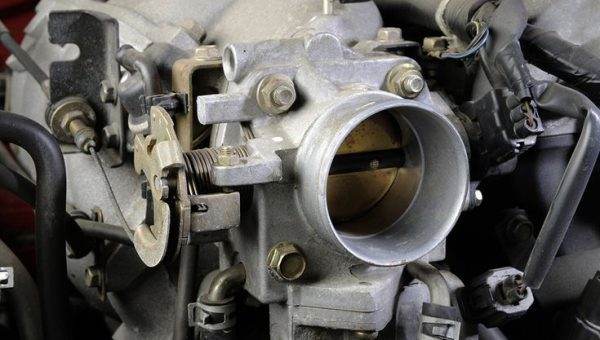
How to Clean the Idle Air Control Valve
Did you know that an air control valve is typically a place where high-density carbon accumulates, which will prevent fuel flow and stop your engine from running efficiently? Periodic cleaning of this small valve is therefore an important step to avoid rough driving and save your money. In this article, we will quickly show you how to clean the idle air control valve on your fuel-injected vehicle. Some vehicles are built a bit differently, but the process is generally the same.
What is an IAC Valve?
The idle air control valve is a part commonly installed in fuel-injected vehicles with the function of allowing your engine to idle efficiently rather than stalling when your car stops. Often, an IAC is attached to the engine throttle. And its purpose is to regulate the airflow into your engine and help create a smoother idle.
The IAC controls the amount of air entering the engine in a cyclical manner. This process is accomplished by regulating the airflow through a bypass circuit around the throttle to increase or decrease the idle speed. Increasing the volume of air flowing in the bypass circuit around the throttle increases the idle speed.
When we talk about engine idle speed, it is the engine’s rotational speed when the driver’s foot is not on the accelerator pedal. When the throttle is closed, the engine’s main intake manifold is closed. So a bypass is necessary to prevent the engine from stalling.
We cannot deny that an IAC valve is a very important component in a car’s engine. A problem with the IAC valve can lead to major issues with your engine. To keep this valve always in good working condition, cleaning the idle air control valve is a key factor.
How to Clean the Idle Air Control Valve?
Over time, the IAC valve will accumulate carbon that clogs or dirties this valve, and the consequence is less airflow entering your engine. At that point, you will have 2 options: replace an idle air control valve or clean it, depending on the condition of this valve you will make the right decision. However, did you know that an IAC valve is one of the most expensive components used in your engine system?
So you can absolutely save a large sum of money from buying a new valve by cleaning the existing one. If you wish to perform this process yourself, it is important that you consult your car’s owner’s manual when you intend to clean the IAC valve. You won’t want to cause further damage, and the manual should provide you with accurate information on how to properly clean the valve.
However, if you cannot find the relevant information, here is a step-by-step guide on how you should work with most vehicles when cleaning an IAC valve. But before starting a process, you must ensure the engine is off and completely cooled down, or you can disconnect the negative battery cable:
Step 1: Locate the Position of the Idle Air Control Valve
It will be difficult to identify the exact position of an IAC valve if this is your first time cleaning this valve. The idle air control valve is usually near the throttle position sensor connected somewhere around the throttle body. For beginners, this can be a bit tricky; you can start by locating the air filter housing and then follow the duct that will pass through the mass airflow sensor and further into the engine. Here, you can find the throttle body as well as the idle air valve. Make sure to find the correct IAC valve, or you might destroy the entire engine by finding the wrong valve.
Step 2: Detach the Air Intake Hose and Filter Housing
The next step is to use a screwdriver to loosen and remove the screws used to secure the filter housing. In this step, you should also disconnect the electrical line associated with the MAF sensor in case your vehicle has issues! However, be careful with the part of the plastic tab that secures the harness.
Do not break it because the wire leading to the harness will detach. And that will cost you much more time to handle and will be more complicated than cleaning the air valve. The harness is prevented from shaking using this plastic tab. Our advice: Make sure not to mess up all the wiring and hoses. After removing the air intake, you can reach the idle air valve. If you still cannot find it, you can refer to the vehicle’s manual.
Step 3: Remove All Clamps Connected to the IACV
Detach all clamps holding an IAC valve. Remove the old gasket (no need to scrape it as it is a metal gasket). In this step, you will find the throttle body, and your task is to place a small hole or passage inside.
Step 4: Clean the Idle Air Control Valve
Use a brush to remove dirt on the surface of the valve. When cleaning the inside of the valve, you will need specialized detergents like carburetor cleaners. Wipe or spray the inside of the triangular face to clean any deposits to ensure no carbon residue remains. Spray carburetor cleaner on the pointed end of the valve. Try not to get cleaners into the valve housing as this could cause damage.
Continue spraying the cleaners until you see that all carbon or debris has been removed. Remember that not all carbon cleaners are suitable for all vehicles and components. You should only use the products if you are sure they will not cause any harm. After completely removing the carbon, the air valve should be reassembled in the detached position, and the harness attached to its original position.
Step 5: Test by Starting Your Car
The best way to check your engine after completing the cleaning process is to let your car start and then idle for a few minutes. Once everything is properly reinstalled, you can now start your car and listen to how it idles. If dirt was a problem, you should now notice the improvement in sound, and your car will run smoothly. At that point, it means your mission is successful; otherwise, you will need to redo the above steps once more. After cleaning and it’s still not effective, it’s time to replace the idle valve. You should buy spare parts from reputable stores to avoid purchasing counterfeit or poor-quality products.
Here are some other frequently asked questions about an IAC:
How to Test an IAC Valve?
There are many ways to help you test the idle air control valve, such as starting your car, testing an IAC with a multimeter, an OBD scanner, or a voltage test light. We believe the simple method you can use to test the IACV is to turn on your car and listen to the engine idling. A fully functional valve will sound even and smooth, and you won’t notice any “bursts” of sound or speed. Additionally, you can use a multimeter, but this method will be a bit complicated.
You need to set the multimeter unit to Ohms, after that, place the red wire on one terminal of the IAC valve and place the black one on the other terminal. If your IAC valve is working properly, the resistance will range from 7 to 25 Ohms, depending on your vehicle. Any other number is a warning sign of a bad IAC valve. To learn more about the process of testing your IAC valve, you can read another article on our site:
What are the Symptoms of a Bad Idle Air Control Valve?
It is important to be aware of the symptoms of the idle air control valve when it goes bad. These include stalling, poor acceleration, increased RPM, or a check engine warning light on your dashboard. If you notice any of these signs, you should immediately test or check if your IAC valve has faults. It is important to know the recommended idle range to give the exact diagnosis because this data will depend on your engine type.
What Happens If You Unplug the IAC Valve?
You can absolutely unplug the IAC valve, and it should not cause damage if you unplug it while the engine is idling. However, the IAC valve plays an important role in maintaining airflow for combustion at idle. So there is a risk when removing this valve causing undesirable effects.
Final Thoughts
An IAC valve may not function properly because it is dirty and requires cleaning maintenance. During combustion, carbon and debris can deposit on the IAC valve, and this can accumulate over time. When contamination builds up inside the idle air control valve, the IAC can then become faulty and not function as it should. Cleaning all accumulated debris or contamination can help you get the IACV back into working order.
In this article, we explained how to clean the IAC valve by removing it. If you want to learn how to clean the idle air control valve without removing it, there will be several guides available online that you can refer to. Although the idle air control valve is designed to last the lifetime of your car, damage and debris can sometimes cause problems. Cleaning this valve is a very useful way to keep your car running efficiently.
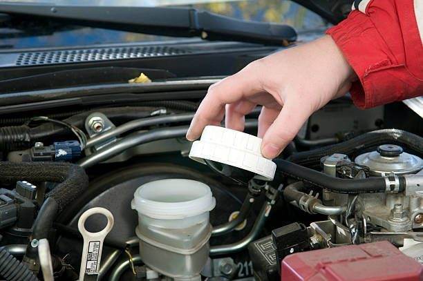
What does it mean if the brake fluid is black?
Did you know that brake fluid colors are important signs that can tell you a lot about your vehicle’s condition? Many drivers worry when they notice that the brake fluid turns black or dark. What does it mean if the brake fluid is black? Let’s take a look at our article to find out the reasons behind this problem.
Why are brake fluids necessary for your car?
According to statistics, every 16,000 to 25,000 km, the driver presses the brake more than 75,000 times. This number has proven the importance of the braking system in your car. Therefore, to ensure the braking system works effectively, it is essential to check and maintain the car’s brakes, including adding car brake fluid.
Automotive brake fluid is a liquid formulated from highly refined base oils and versatile additives. This fluid is responsible for supporting the transmission of force from the brake pedal to the components of the braking system. In addition, brake fluid also has the important function of lubrication, preventing corrosion. And reducing friction which helps the braking system operate smoothly.
What color should brake fluid be?
It can be said that the brake fluid color is an essential indicator that tells you whether the brake fluid is in good condition or needs to be changed. Black brake fluid can be a warning that your car has a problem. However, before determining whether this is a normal phenomenon or not, you need to determine the color of the brake fluid. Currently, most brake fluids are manufactured according to DOT standards. This standard is determined based on the lowest boiling point and the brake fluid’s ability to maintain performance. There are 4 types of automotive brake fluid according to DOT standards: DOT 3, DOT 4, DOT 5, and DOT 5.1. DOT 3 and DOT 4 are the two most common types. Depending on the type of brake fluid your car uses, the colors will vary, including:
DOT 4 and DOT 5.1 are yellow in color.
DOT 3: This type of fluid is only used for racing cars. DOT 3 is blue.
DOT 5: This fluid has a purple color.
However, all you need to remember is that healthy brake fluid will be almost clear with a yellow tint. This color should resemble the color of the bottle before you initially pour it into the car’s reservoir.
When brake fluid is contaminated, it will appear in a brown or dark color (Photo: pinterest.com)
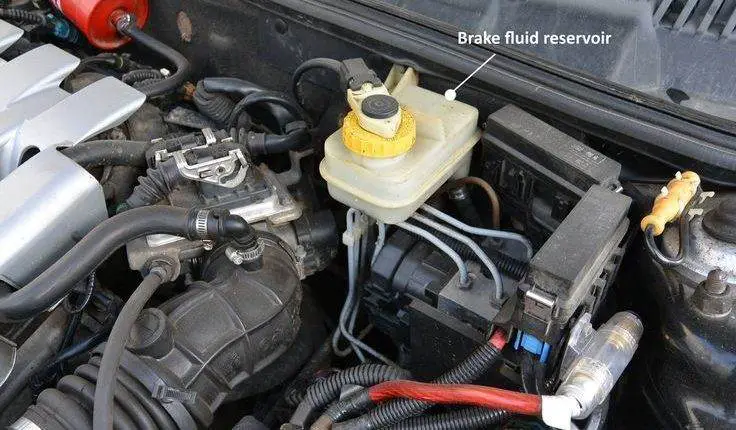
Brake fluid is black: what does it mean?
If you open the car’s brake fluid reservoir and notice black or brown fluid. So what happened to your car? We are sorry to say that black brake fluid is a sign that your fluid is heavily contaminated. When this happens, the braking system’s ability to pressurize is reduced and braking performance can be affected. Furthermore, black brake fluid means the rubber seal has deteriorated and the fluid in the reservoir is too old and needs to be replaced. In fact, it turns out that the contaminants in the brake fluid attack the rubber seals and washers. The black color of the fluid corresponds to the carbon particles from the rubber pads.
Why does brake fluid turn black?
Many drivers have stated that black brake fluid was caused by its age. This is a true opinion. Like other fluids, brake fluid degrades after a long period and needs to be replaced. After some time, your brake fluid will accumulate enough contaminants and cause a color change. This change will go from clear/yellow to a darker yellow, and when the brake fluid is brown or black, it can seriously affect the braking system.
Inside the braking system is the brake fluid reservoir. From this reservoir, the brake fluid moves from the cylinder to the car’s wheels. If you press the brake frequently, the brake fluid will become contaminated faster. And even if you don’t drive that hard, due to its characteristic, your brake fluid will still accumulate contaminants over time.
The second cause of brake fluid discoloration is the deterioration of some parts of the braking system such as the rubber brake lines, the slave cylinder seal, or the wheel. Because brake fluid is corrosive. Even though the braking system components are designed to withstand such corrosion. If they are not maintained or serviced properly, these parts will show signs of wear. At this point, microscopic pieces and soot from the rubber will follow the path to enter the brake fluid. Discoloration as well as the reduction of the fluid’s efficiency.
Why is brake fluid easily contaminated?
Black brake fluid is caused by its age after a long period and it needs to be replaced (Photo: istockphoto.com)
Although the brake is a sealed system, vapor can still pass through the micro-holes in the rubber hose and the sealing ring. Meanwhile, car brake fluid is easy to boil due to its great ability to absorb moisture, leading to decreased brake pressure and poor braking efficiency.
Furthermore, in countries with humid climates. The details of the braking system are also prone to rust when the brake fluid “saturates” with water when the vehicle moves in rainy or flooded weather. In addition, lack of brake fluid or degraded oil is the cause of damage to the braking system such as strange noises, low pedals, a strong braking sensation, and the most extreme is the phenomenon of the car losing its brakes…
According to automotive experts, brake fluid contains corrosion inhibitors and antioxidants. Over time, the structure of these substances breaks down, leading to metal corrosion and the accumulation of deposits that disrupt the flow of brake fluid.
Can you drive when the brake fluid is black?
Black brake fluid is absolutely not a good sign. This color indicates that there is probably moisture that has seeped into your fluid and dramatically affects the quality of the fluid. The main function of brake fluid is to make your brake fluid more fluid. What will happen if the brake fluid loses this functionality? This is therefore the reason why many experts advise against driving your vehicle with black fluid. Although black brake fluid does not always trigger an alarm, using black fluid can cause serious problems.
This fluid content can corrode the steel components of your braking system and damage them. Brake fluid used for a long time without replacement will lead to corrosion of the wheel cylinders; the brake pedal is not effective; the brake pads are quickly damaged… Many parts and components are worn and damaged affecting the entire braking system and vehicle; even your own driving.
Furthermore, the boiling point of contaminated brake fluid will be lower than that of clean brake fluid, thereby reducing braking efficiency. When driving, using the brakes generates a large amount of heat. Therefore, traveling with dirty brake fluid, when the fluid boils, creates a large amount of foam and gas. Over time, the car’s brakes are damaged. This is very dangerous when you are driving on the road.
How often should you replace brake fluid?
Brake fluid can be contaminated by 2% water in the first 12 months and reach 7 to 8% after just 36 months. If you do not change the fluid in time, it can damage the braking system during operation.
According to manufacturer recommendations, brake fluid should be changed every 3 years or after 30,000 to 40,000 km. If the vehicle constantly moves in dusty and very humid conditions or uses the brakes continuously. The car owner can change the brake fluid earlier.
After that, you need to take your car to the mechanic to have it repaired to ensure everything is safe. To know exactly when to change the brake fluid, car owners can check the actual quantity and quality of the oil in the reservoir via the brake fluid sensor equipped on the vehicle or check it manually. In case of manual inspection, observe only from the outside. Do not open the lid to prevent air and moisture from entering. The color will reflect the quality of the oil. Standard brake fluid is clear or colorless; if it turns brown. This means the oil has severely deteriorated and needs to be replaced to protect the braking system.
Steps to change car brake fluid
Dirty brake fluid can damage the braking system during operation. (Photo: pinterest.com)
When checking, if the oil level is low but the color is clear or yellow. The car owner just needs to add more oil to the reservoir. Brake fluid should be replaced when it shows dirt or turns dark brown. Basic tools for changing brake fluid include a suction system, a car repair kit, a car jack, brake cleaning spray, and grease for bolts and screws.
Step 1:
Remove the wheel and clean the car’s brake with a specialized cleaning solution.
Step 2:
Find the position of the top of the fluid hose and remove the rubber buttons that cover the outside of the hose. Proceed to place a plastic tube into the reservoir and open the drain valve to let the old fluid out. This method minimizes the return of air into the brake cylinder.
Step 3:
Insert a piece of wood so that the brake pedal does not come off too much when the oil pressure is released.
Step 4:
Open the brake fluid reservoir cap, use a straw to suck out all the used oil, pour in new oil, and close the reservoir cap tightly.
Step 5:
Hold the brake with a constant force, tighten the drain valve bolt, then loosen it a quarter turn to drain all the used oil. Then, retighten the bolts, remove the plastic tube, and install the rubber-covered buttons as before.
After completing the brake fluid change steps, the car owner starts the engine, presses and releases the brake pedal to check the stability of the braking system.
As the “lifeblood” of the hydraulic braking system. Brake fluid must be periodically maintained and replaced to limit brake degradation and prevent operational risks.
To maximize the efficiency of power transmission, car owners should choose a non-compressible brake fluid that can lubricate the brake calipers to help reduce corrosion and has high boiling points. It is recommended to use a specialized brake fluid specific to each vehicle model according to the manufacturer’s recommendations. This not only helps to maximize the efficiency of the car’s brake fluid but also ensures the lifespan of the braking system.
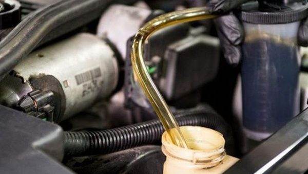
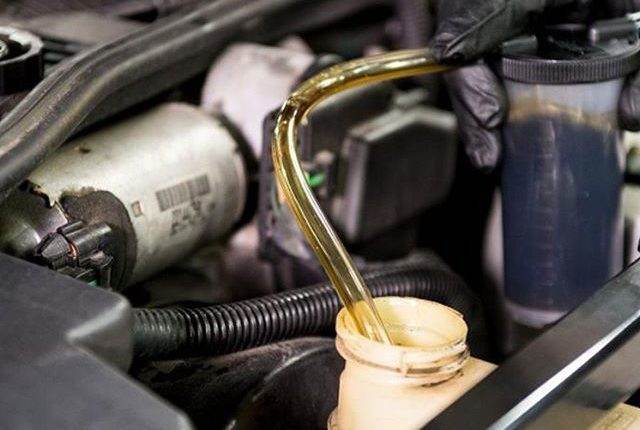
What is the normal oil pressure at idle?
Knowing what the proper oil pressure should be can help you ensure that the car’s engine is running correctly and remains healthy. If you notice low oil pressure, the amount of oil supplied is not sufficient for lubrication, which will result in high-friction components in the engine wearing out quickly, becoming noisy, and easily increasing heat. This means that low oil pressure is a warning sign for your engine. Are there exceptions? Many drivers while driving cars have noticed that oil pressure drops at idle. So why? and what is normal oil pressure at idle?
What is Normal Oil Pressure at Idle?
Oil pressure is a vital indicator in car engines that you must consider. However, it will vary depending on certain factors: engine types and temperature. To know the exact oil pressure at idle, first, let’s take an overview of oil pressure.
What is Oil Pressure?
Automotive engine oils operate in the form of a circulation system. The oil is injected by the pump into the engine, then flows into the reservoir, then continues to be sucked through the filter and sprayed into the engine. Oil pressure is created by the pump pumping oil into the vehicle’s engine system. When the engine is running, normal oil pressure is typically between 25 and 65 PSI (depending on the vehicle model). Normal oil pressure always remains stable at this level. If the oil pressure suddenly increases or drops abnormally low, it is a sign that the lubrication system has problems.
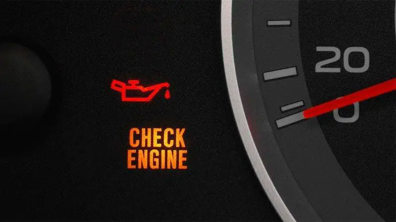
Cars are equipped with an oil pressure sensor. If it detects that the oil pressure is too high or too low, the sensor will transmit a signal. And the ECU will illuminate the lubrication oil pressure warning light to inform the driver. When you see that the car has abnormally low or high oil pressure, it should be checked as soon as possible. Because the malfunction of the lubrication system will greatly affect the engine.
What Should Oil Pressure Be at Idle?
To ensure your car’s engine operates with the best performance. Car manufacturers recommend that the oil pressure should always be above 20 PSI (pounds per square inch) at idle. However, corresponding to each vehicle type, we will have different pressure levels:
Truck: 20-30 PSI at idle
Car: 25-35 at idle
Most car manufacturers suggest that the oil pressure should be around 30 PSI at idle and about 60 PSI when the engine is running at higher speeds. If you check that the oil pressure is below 20 PSI. If you notice that the oil pressure is below 20 PSI, you need to check it as soon as possible. As we all know, engine oil not only helps the moving parts of the engine to function correctly but also helps to cool them. If the pressure is too low, the engine will not be properly cooled and this can have serious consequences.
This difference in oil pressure will occur when the oil’s viscosity decreases due to heat. Most vehicle engines have an oil pump. The principle is to increase pressure with speed, so the engine runs higher and the result is that the oil pressure increases. This function ensures that your engine parts are sufficiently lubricated as they move faster and start generating more heat. When your car is idling, you do not need high oil pressure. 20-25 PSI is sufficient for most engines. Just make sure that the pressure will increase when your car increases its speed.
What Causes Low Oil Pressure at Idle?
If you notice that the oil pressure is too low at idle (below 20 PSI), it can be a symptom telling you that there is a problem with your car. If the oil pressure is below the standard level, the engine will not have the necessary amount of lubricant. This makes parts and components easy to wear and causes overheating and damage. As we know, oil pressure at high speed is about 60-70 PSI. Why is oil pressure low during idle operation – Let’s look for the causes:
The Car Lacks Engine Oil
Car oil shortage is the most common cause of oil pressure drop at idle. Because the amount of oil is not supplied to the engine, the oil pressure drops. To know exactly if this is the cause, check the available oil quantity with the dipstick. If you see that the oil quantity is too low, near or below the low level, that is the reason. There are several reasons why the car is low on oil, such as the car hasn’t been changed for a long time. Oil is leaking due to open pipelines, or worn crankshaft bearings…
Dirty Oil
Engine oil is responsible for cleaning the internal components of the engine. Therefore, over time, it will accumulate many impurities and residues. On the other hand, due to working in a high-temperature environment, the oil also gradually degrades. If the oil is not replaced periodically, it will become heavier and denser due to dirt (low viscosity) causing the oil pressure to drop or increase easily. Seriously affecting the efficiency of engine lubrication – cooling – cleaning.
The Oil Pump/Oil Filter is Damaged
If the pump system is damaged, if oil cannot be sucked normally, or if the filter is clogged, it will make it difficult for the oil to circulate. From there, leading to a low oil pressure error or loss of oil pressure. Therefore, you need to pay attention to choosing oil with the correct viscosity for your vehicle to avoid low oil pressure. Furthermore, it is also important to carefully learn about other oil specifications such as API, ACEA, etc., to buy the best product.
Oil Pressure Sensor Malfunction
Most cars today are equipped with an oil pressure sensor. If it detects a problem with the oil pressure (too low or too high), this device will send a signal to the ECU. The warning light then illuminates to remind the driver to correct the error. However, sometimes the sensor is dirty or damaged, so it sends the wrong signal, even if the oil pressure still maintains a stable level.
Using Oil with a Low Viscosity Index
The viscosity index (SAE) is a measure used to identify the density of the oil. More specifically, the lower the SAE, the thinner the oil will be. For example, Essenza high-displacement 10w30 oil will be thinner than 10w40 oil. If the viscosity index is too low, the oil is too fluid and the oil pressure in the engine is reduced.
How to Fix Low Oil Pressure at Idle?
To keep the engine in perfect operating condition, the oil pressure must be checked periodically and within the range recommended by the manufacturer. The oil will thicken and have higher pressure when the engine is cold. Whereas the oil pressure will decrease as the engine warms up. To ensure accuracy, we must check the oil pressure when the engine is at operating temperature.
Step 1: Check the Oil Level.
Open the hood and check the vehicle’s oil with the dipstick. If the oil in the car is still full and the oil pressure light is on, it means the car has other problems. If the oil level is below the marked position, at that time, the car is out of oil and needs to be replaced.
Step 2: Inspect the Oil Pressure Sensor.
Remove the sensor, insert the pressure gauge, and start the car. If the value returns to the standard oil pressure value, the sensor is faulty. If the return value is lower than the standard value. The sensor is still working fine, but the oil pressure is low for other reasons.
Step 3: Don’t Forget to Check the Oil Filter/Pump
Remove the oil filter and check that there is no debris. If there is, you need to clean it (or replace it if necessary). According to experts, the car’s oil filter should be changed approximately every 10,000 miles.
If the car has very low oil pressure or no oil pressure, check the oil pump drive belt.
Step 4: Check the Crankshaft Bushing
Check the condition of the crankshaft bearings. If signs of wear are detected, it is likely the cause of the oil leak, reducing oil pressure at idle. The solution, in this case, is to replace the crankshaft bearing with a new one, then add engine oil.
Final Thoughts: What is Normal Oil Pressure at Idle?
20-35 PSI is the answer to this question: What should my oil pressure be at idle? In this article, we have outlined the causes of low oil pressure at idle and how to check and fix it quickly. I hope this article has provided you with useful knowledge.
Reasons why diesel engines last longer
Diesel Engine Myths: “Diesel engines last so long.” This myth formed long ago, however, this question is constantly questioned and debated by many drivers. Why do diesel engines last longer than gasoline engines? Let’s break it down and compare diesel and gasoline engines. From there, we will answer the question and clarify it!
How does a diesel engine work?
For some car owners, diesel engines do not seem to be a smart choice. Noisy, smelly, and heavy are the characteristics that everyone seems to be able to highlight when mentioning diesel engines. However, it is undeniable that diesel engine cars are still highly valued, especially among experienced drivers. As part of this article, we will soon discover how diesel engines work to understand the idiosyncratic characteristics of this engine.
A diesel engine is a type of internal combustion engine, different from a gasoline engine. The combustion of fuel, i.e., diesel, occurs in the combustion chamber when the piston approaches top dead center during the compression stroke, which is a spontaneous combustion under the influence of high temperature and pressure of the compressed air.
In diesel engines, the operating cycle starts with pure air drawn into the cylinder, not an air-fuel mixture as in conventional gasoline engines. The piston’s movement compresses the air, heating it to a high temperature. When the piston gets closer to the top of the cylinder, fuel is injected under high pressure through the number of precisely machined holes in the tip of the fuel injectors. At this point, the fuel enters the engine in the form of a fine spray. Spontaneous ignition occurs without needing a spark and the rapid expansion of the combustion mixture increases the pressure in the cylinder, forcing the piston downward and powering your vehicle.
How long does diesel last? If well maintained, diesel engines can run for about 30 years (Photo: pinterest.com)
How long do diesel engines last?
If you want to buy a car with features such as reliability, robustness, and high lifespan, diesel engines might be a good choice for you. Why did we say that? Can you guess the average lifespan of a diesel engine? The truth has been revealed, vehicles equipped with gasoline engines can travel about 250,000 to 300,000 miles before needing a major overhaul or a brand new car. And you might be surprised to know that diesel engines can last up to a huge number: 1,500,000 miles before their performance decreases.
From this number, we can estimate that, if well maintained, diesel engines can run for about 30 years. Of course, the longevity of diesel engines will depend on many factors like any engine. How you maintain the engine, your driving styles, and other external factors… All these will determine the lifespan of diesel engines.
Why do diesel engines last longer than gasoline engines?
Based on the figures from the section above , how long does diesel last? You can see that diesel engines can last almost twice as long as gasoline engines if well maintained. As a result, diesel types are known for their longevity, with engines typically lasting longer than the rest of the vehicle. Why do diesel engines have such a big difference like that? Let’s find out:
Why is diesel heavier than gasoline? (Photo: pinterest.com)
Diesel fuel has very good lubrication
Diesel is a light oil and when burned and used as fuel by the vehicle. It lubricates the parts of your engine. Diesel is among the fuels that can only evaporate at high temperatures (ranging from 175 to 370 degrees Celsius), which helps limit engine wear during use. As we all know, gasoline is a solvent. Any gasoline that has not been burned tends to wash the oil off the cylinder walls, increasing wear. Diesel fuel is a light oil, it can reduce the viscosity of the lubricating oil, but not to the same extent as gasoline.
Because gasoline does not have the ability to lubricate very well (gasoline is considered an excellent cleaner), over time, it can increase the wear of your engine. Proven diesel fuel has better lubricating power above the piston rings in the combustion chamber. And the wear process in a cylinder occurs more slowly than in gasoline engines because diesel fuel is essentially a distilled fuel. Thanks to its exceptional lubricating properties, diesel engines have a better lifespan than gasoline engines.
Design of a diesel engine
This can mean there are many differences in the design of a diesel engine that will allow it to run longer than a gasoline engine. A diesel engine is a great example of engineering capability. The components of this engine are generally more durable than gasoline engine parts. The design of a diesel engine is gear-driven, so unlike other parts, the gear can be easily fixed and never lose its timing. In diesel cars, use gear-driven water and oil pumps to avoid the risk of major component failure. Whereas gasoline engines use timing belts, pumps, chains, and other components that can easily wear out and break frequently.
Furthermore, diesel engines have a fuel injector and also excellent self-cooling which will minimize the risks of overheating. Compared to gasoline engines, diesel engines are supposed to be 1.5 times more powerful. Because diesel engines often have a higher compression ratio, maintaining better operating efficiency over time. It is not uncommon for diesel vehicles to exceed the 1.2 million mile mark on the speedometer and still run smoothly.
Diesel engines operate at lower RPMs
If you own a car with a diesel engine, you will notice that the redline on the tachometer is much lower than the gasoline engine. The redline displayed on diesel engine gauges usually does not exceed 4500 RPM, this figure is only about half that of gasoline engines. Why does this happen? Diesel engines tend to have lower RPMs because they have a longer and heavier stroke. With larger strokes, they can produce a lot of torque. To clarify things, we will summarize 3 reasons why diesel engine RPMs are lower:
Have a longer stroke length.
Diesel engines are designed heavier.
They are compression-ignited.
The higher the RPM, the more things break and wear out quickly. So we believe you had an explanation for why a low-revving engine typically lasts much longer than a high-redline engine, because the driver cannot rev the engine beyond 4500 RPM.
Unlike gasoline engines, diesel engines of the same displacement and same number of cylinders always dominate in torque, especially in the high-end. With a thicker inline-four-cylinder structure, the diesel engine easily achieves a torque of over 450 Nm from around 1,500 to 1,800 RPM. Meanwhile, to reach this level, the gasoline engine would have to switch to a 4.7-liter V8 (if it doesn’t use a turbocharger system), but also from 3,400 RPM or more, i.e., much later.
Is diesel better than gasoline?
From the above analysis, we can see that the diesel engine has a longer lifespan than the gasoline engine. So does that mean the diesel engine will be better than the gasoline one? Although they are more fuel-efficient and durable, diesel engines are still not the first choice for drivers. Why? Let’s briefly list a few advantages and disadvantages of diesel engines compared to gasoline engines:
What happens if you put gasoline in a diesel engine? (Photo: pinterest.com)
Advantages of diesel engines over gasoline engines
Diesel engines are safer because diesel does not ignite at normal temperature, so there is less risk of fire than gasoline engines.
Furthermore, diesel engines are less prone to breakdowns than gasoline engines due to the absence of carburetors and spark plugs.
At the same time, diesel engines have better load capacity than gasoline engines.
About the disadvantage:
Compared to gasoline engines, diesel engines have a heavier weight and higher manufacturing costs due to their higher compression ratio, which requires more engine parts.
Repairing diesel engine parts requires specialized machinery, high-quality tools, and highly skilled technicians.
Because they are heavier and have a higher compression ratio, diesel engines often have a lower redline than gasoline engines. The result is that diesel engines have high torque instead of high power, resulting in slower acceleration.
The above disadvantages are only historical, explaining why diesel engines were not chosen by the majority in the first place. Currently, as technology develops, companies are gradually eliminating or limiting the above disadvantages, making diesel engines more suitable.
Therefore, one cannot claim “Is the diesel engine better than the gasoline engine” or vice versa. Based on the difference in operating principles between the two types of gasoline and diesel engines. You can make the decision to choose the right car for you. Because each version has its own strengths or limitations.
Useful tips to extend the lifespan of diesel engines
Although diesel engines are considered more durable than gasoline engines. For diesel engines to operate at maximum efficiency, drivers must follow maintenance guidelines:
Use the right diesel for your vehicle
Maintaining diesel engines has a few small differences compared to gasoline engines when changing oil for diesel engines. Drivers must change the correct type of oil according to the vehicle’s specifications to limit unnecessary damage. To know the right lubricating oil for your car. You can refer to the user manual or you can contact reputable maintenance centers. Where technicians will advise you on the best oil for your vehicle.
Periodically change the oil filter
Over time, dirt will accumulate and clog the oil filter. The consequence is that dust will follow the oil to the engine parts, directly affecting the engine’s operation. Therefore, periodic inspection and replacement of the fuel filter are essential. According to the manufacturer’s recommendations. You should periodically check the oil filter after 1 to 2 months of use or after 5,000 to 7,000 km. Depending on the engine’s operating level.
Clean the injectors after some time
For diesel engines, the injectors and lubrication systems must be cleaned periodically. The inside of the combustion chamber of diesel engines does not use spark plugs to ignite the fuel like a gasoline engine. Therefore, the fuel injector must always ensure that the injection is smooth and unobstructed to increase the direct ignition and explosion capability. With diesel cars, care must be taken to clean the injectors periodically every 20,000 km.
In addition to the above tips, there will be a few notes for you when driving a diesel car in cold weather. Before starting the engine, it is necessary to turn on the electric lock at the preheating stage. At this point, the glow plug will heat the oil inside the combustion chamber to thin the oil and prevent it from freezing. When the preheating light on the dashboard goes out, start the engine.
Final thoughts: Why do diesel engines last longer?
Reading this far, we will probably see that it is no longer a mystery. When we know that diesel engines have a significantly longer lifespan than gasoline engines. However, you will be surprised to know if a well-maintained diesel engine can travel over a million kilometers or more. Hopefully, with the information from our article, you will have the necessary information about diesel engines.