Having a weak battery when you’re in a hurry is frustrating, and worse, it could leave you stranded. Although there are many reasons why your battery may keep dying without warning, you can do certain things to get the juice back into your vehicle, depending on how “dead” your battery is.
It’s one of the basic skills of car maintenance to know when a dead battery is actually the cause of starting problems, how to check if your battery is dead and how dead it is, and whether you can recharge a completely dead car battery. In this article, you’ll learn the signs of a dead battery and how to revive it, as well as understand what happens inside a battery when it’s dead, when a battery can no longer be revived, and tips to avoid completely draining your precious battery.
When is a Battery “Dead”?
“A dead battery” can be a confusing description. Usually, it’s a battery that is depleted or discharged to such a low level that it won’t provide enough power to effectively start the engine, so you’ll have difficulty starting your car, or your car might not start at all.
However, there are different “levels” of battery “death.” A battery can be dead, but almost, which is when it’s depleted or discharged to a dangerous level but can be recharged again. A battery can die like this and be revived a number of times during its life, but after a certain point, it will truly die and can no longer be revived. The only option then is to replace your battery.
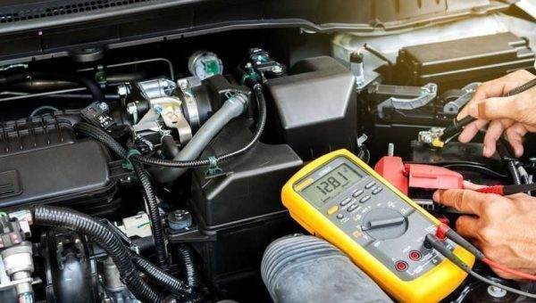
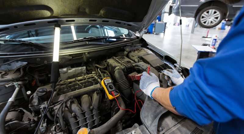
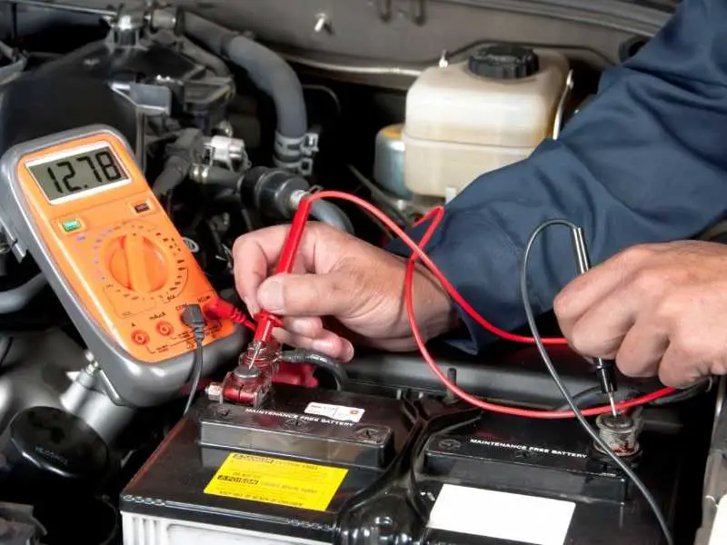
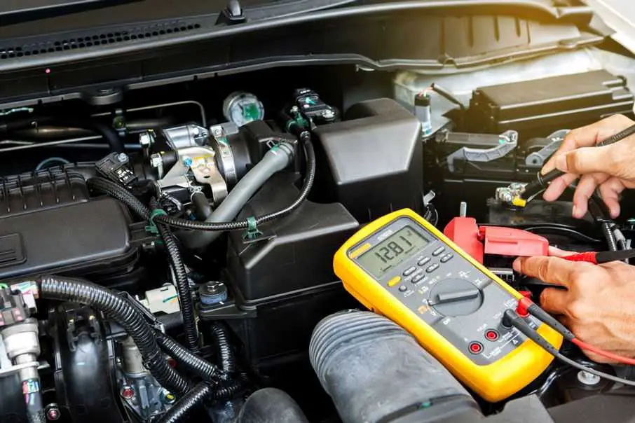
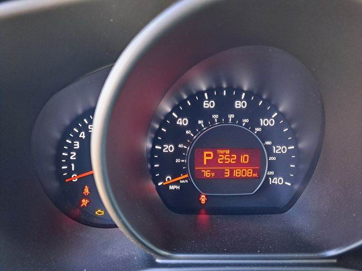
It’s important to know how dead your car’s battery is before deciding how to recharge it. For this, you’ll need a multimeter or a voltmeter, both are cheap and handy devices for diagnosing battery problems. A healthy battery will show 12.4 to 12.7 volts at both terminals.
If the voltmeter shows less than 12.4 volts, you’ll likely encounter problems when trying to start your vehicle. The lower amount will determine the method you need to use to charge the battery after starting your vehicle, and below a certain point, your battery will be truly “dead,” meaning it cannot be revived in any way and must be replaced.
If you experience one or more of the following symptoms, a dead battery is most likely the culprit. Some of these telltale signs can also be caused by other underlying issues elsewhere, so it’s important that you test your battery’s voltage with the appropriate tool after encountering these problems to check its condition.
The Engine Doesn’t Start
Your car relies on your battery to start and run the engine. So, when your car’s battery is dead, the most obvious sign is that the engine doesn’t start when you turn the ignition key. That said, there are many possible reasons for a hard starting problem. To narrow down the culprit, you’ll need to listen carefully when turning the key.
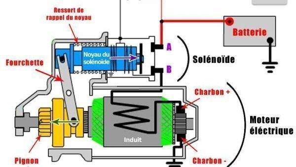
If you hear and feel nothing at all when turning the key, it means the starter isn’t getting power. The starter is responsible for turning the engine over when you turn the ignition to initiate the engine’s operation by its own power.
When in addition to this symptom, you also experience one or more of the issues below, it’s highly likely you’re dealing with a dead or depleted battery. Otherwise, there are other underlying causes, including a faulty ignition switch or a blown fuse.
The Engine Doesn’t Start but the Starter Cranks
Another possibility is that when you turn the ignition key, the engine doesn’t start but you hear the starter. The starter always makes a distinct sound when it engages with the engine via a flexible toothed plate or flywheel and physically turns it over. You should be quite familiar with the sound your car makes when you turn the key.
If one day it sounds different or you don’t hear it at all (as in the symptom above), there’s a problem with the starter itself or the battery or other parts. How the sound changes can help you identify the culprit.
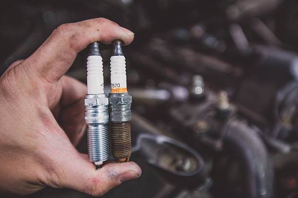
If the starter cranks at a normal speed, then you have a fuel problem or a faulty spark. If the starter cranks several times then stops completely, or cranks very slowly and seems labored, you’re dealing with a dead battery or a faulty starter.
The most common cause is that the battery doesn’t have enough charge or voltage to operate the starter properly. So, the starter may be able to turn the engine over, but doesn’t provide enough power for the engine to start and run on its own. In some cases, a faulty starter may try to draw more amperage or current than the battery can supply.
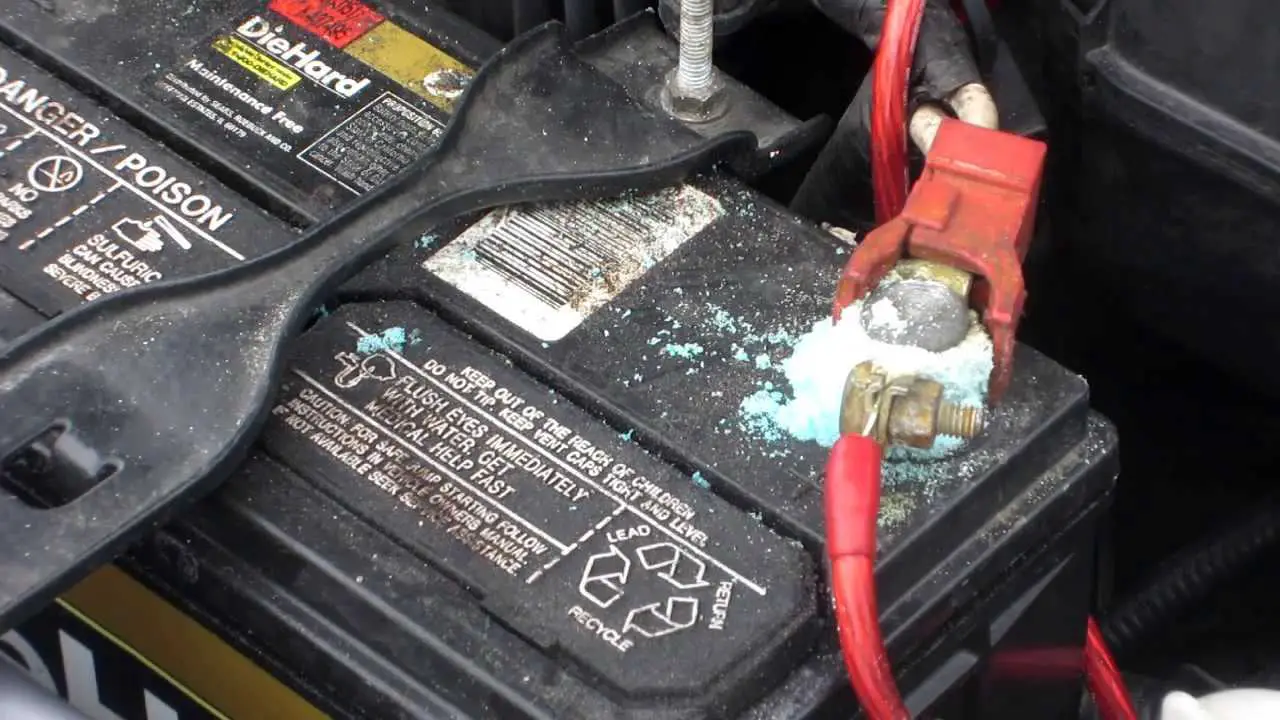
To identify the culprit, you need to perform a battery test using a multimeter or voltmeter to check if the battery has sufficient voltage and if all battery terminals are tight and clean (without corrosion). If the battery is intact and not dead, you can suspect a faulty starter. You should use an ammeter to check that a faulty starter is indeed drawing too much amperage from the battery before proceeding with starter replacement.
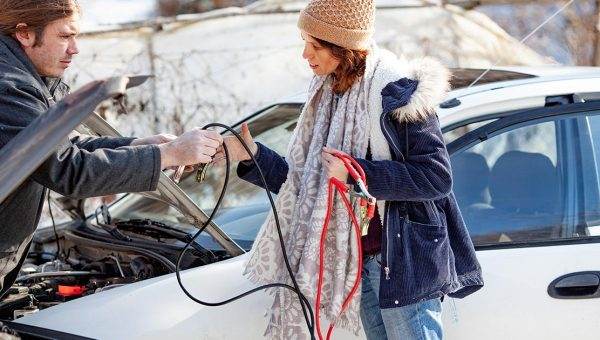
The Car Needs a Jump Start in the Morning
If you can’t start your car one morning without a jump start, but have no problems later in the day, two things may have happened and the battery isn’t actually the underlying cause but only related. First, there’s a parasitic drain on the battery overnight that drained its juice. In this case, your battery may be revived or it may die completely and need to be replaced. In any case, you need to locate the source of the parasitic drain and try to avoid it.
There are a number of electrical accessories in your car, including the stereo system, interior lights, door lights, dashboard, and more. Most of these features typically don’t drain your car’s battery when the engine is off, but small electrical incidents can still occur and drain your battery’s charge overnight. Interior lights (including door lights) and bad fuses are the most problematic sources of potential parasitic leaks. To avoid such electrical incidents, you should make it a habit to turn off all lights and ensure all doors are completely closed and locked before leaving the car, including your trunk and glove box.
The second underlying cause is extreme cold. It’s quite common to encounter hard starting or a no-start problem on particularly cold mornings. Very cold weather can freeze a battery, short-circuit the plates and the battery will no longer charge, or decrease the battery’s ability to provide current on demand to the starter. Lead-acid and lithium-ion batteries are particularly weak in extremely cold weather.
While younger batteries under 3 years old have higher resistance to extreme cold, a battery loses strength with age. So, if you live in a place that frequently drops below freezing in winter and your battery died one morning, you’ll likely need to replace it very soon, even if you might be able to get a few more trips out of it after one of the methods we’ll discuss later. And you’ll want to get a new battery with a higher cold cranking amperage to better withstand extreme cold.
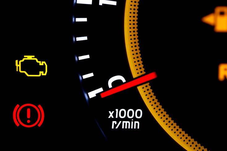
Some Electrical Accessories/Functions Don’t Work
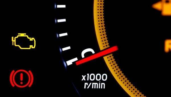
If one day you notice that many electrical accessories or features aren’t working properly or not at all at the same time, it’s usually a red flag that the battery is dead and can’t provide power to operate these accessories.
For example, dashboard lights and headlights may be dimmer than usual or not come on at all, or if you insert your keys while the door is still open but don’t hear the familiar chime, or your dome light doesn’t come on.
Note that if something isn’t working but others still are, the battery probably isn’t dead. For example, if your door chime isn’t working, but other electrical accessories such as dashboard lights, headlights, and radio are working, the culprit is likely a faulty door switch or a blown fuse. Or if it’s only the headlights and radio that won’t turn on, the problem could be a blown main fuse or wiring issues.
What Really Happens Chemically in a Dead Battery?
As mentioned above, whether a depleted battery can be recharged or revived by other methods depends on how “dead” it is. This will decide the best way to revive the problematic battery, or if the battery is truly dead and therefore must be replaced.
Mishandling a depleted and deteriorated battery will only send it to the end of its lifespan much faster and can also put excessive strain on or damage other components of your car. Therefore, before moving on to discussing safe and appropriate ways to recharge or revive a completely dead battery in the next section, you must first understand what happens chemically inside a dead battery.
A car battery is made up of alternating plates of lead (Pb) and lead oxide (PbO2), and these plates are suspended in an electrolyte solution of water and sulfuric acid (H2SO4). When the battery discharges, the battery acid solution facilitates the flow of electrons from the lead plate to the lead oxide plate. This generates an electrical current, which is used to power the engine or operate other electrical accessories.
Due to this chemical reaction, sulfur is extracted from the battery acid and the lead plates of the discharged battery are now coated with lead sulfate (PbSO4). This “sulfation” process occurs virtually every time you discharge the battery and that’s where the potential problem lies.
If the battery is immediately recharged after being discharged, which usually happens, the reverse chemical reaction will occur immediately and reverse the previous sulfation process.
When the engine is running, the alternator charges the battery, or when you connect the battery to a dedicated battery charger, most of the lead sulfate coating on the lead plates returns to the battery acid. At the same time, hydrogen is also released. That’s why it’s possible to charge and discharge a lead-acid battery over and over again.
So, if the battery remains charged, the sulfation process is reversible, which is called “soft” sulfation. However, “hard” sulfation can occur if the car battery is left discharged for an extended period, which refers to the formation of lead sulfate crystals on the battery plates. These crystals gradually reduce the surface area of the plates available for the chemical reaction, thus decreasing the battery’s charge and discharge capacity.
Over time, this will worsen and lead to cracks and short circuits in the battery, and the battery will need to be removed for good.
In other words, while the sulfation process occurring on the battery plates is reversible, not all types of batteries can withstand only a limited number of charge and discharge cycles. Moreover, every time a battery is completely discharged, it suffers irreversible damage. So, a battery can only “die” completely and be recharged a limited number of times before it dies for real and needs to be replaced.
This means, therefore, that although in many cases, as mentioned above, the underlying cause of a hard starting problem is not a dead battery itself and so you just need to fix it and fully charge your battery to bring the battery back to life, a battery that has been jump-started or charged a number of times will need to be replaced anyway.
Can a Completely Dead Battery Be Recharged?
Unfortunately, it’s impossible to reverse hard sulfation. Still, if you have a dead car battery, you can try several things to get back on the road. That said, what you can do depends on the condition of the battery.
If the Battery is Almost Depleted
Driving: As we said, a healthy battery should have at least 12.4 volts of charge. Generally, if the battery still has barely enough charge, meaning if a multimeter test returns a reading between 12 volts and 12.4 volts, you can safely recharge it with your vehicle’s alternator. This means you only have to take your car for a drive to allow the alternator to charge the battery, but you must use as little electricity as possible to ensure nothing is unnecessarily consuming power and the alternator is sending as much power into the battery as possible. It’s best to go for a drive when it’s bright outside and turn off all lights and other electrical systems and accessories. The general consensus is that you should drive the car for at least 30 minutes to give the battery a significant charge and bring it back to a safe level for your next start.
If the Battery is Totally Depleted
A car battery is considered completely dead when the voltage drops below 12 volts. In this case, you cannot and should not try to charge the battery using your alternator as above, because the alternator was never designed to charge a completely dead battery.
Driving your vehicle to have the alternator restore such a completely dead battery means the alternator is forced to overwork to revive the dead battery as well as power other crucial components. This will damage the alternator, and moreover, the alternator cannot provide sufficient power to recharge a completely dead battery, so it only undercharges the battery. Undercharging will shorten the battery’s lifespan, while it won’t be able to effectively maintain the charge provided by the alternator.
Although using the alternator to recharge a completely dead battery is both inefficient and harmful to both parties, you can try the three methods below to safely extract juice from your dead battery:
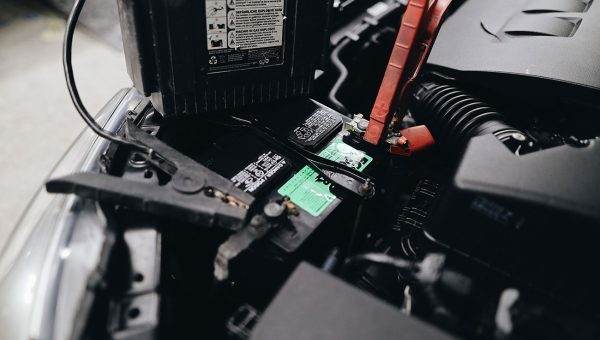
Use a Dedicated Jump Starter/Battery Charger: The safest way to revive a seriously depleted battery is to connect it to a jump starter or a dedicated battery charger before or immediately after a jump start. Both are special charging devices designed to safely restore a dead battery to full charge. Most of the time, you won’t have to remove the battery to revive it.
Note: Do not turn off the engine, as the dead battery won’t accept a charge. Also, in the case where the battery is frozen, do not attempt to jump-start it because the battery case will swell and may explode. Thaw it first.
Distilled Water: If the battery’s acid or electrolyte level is low, a common trick is to add distilled water to fully submerge the plates again, which will allow a bit more space for the chemical reaction to occur. Adding distilled water may be enough to give the engine a few more turns.
Epsom Salt: This may seem surprising, but it’s basic chemistry. Epsom salt is something widely sold in grocery stores and commonly used to relieve muscle pain and constipation. It’s magnesium sulfate or MgSO4 and it’s a strong acid. When the battery’s acid level is low, you can add this strong acid with distilled water to the electrolyte mixture to tip the chemical balance, which might provide enough charge to give the engine a few more turns. Dissolve the Epsom salt with warm distilled water in a 1:3 ratio, then add to each cell until ¼” to ½” of the plates are submerged.
When a Dead Battery Can No Longer Be Revived
Even when you can get your car back on the road after a jump start or after recharging your dead battery with a dedicated charger, the buildup of hard sulfation is irreversible and will lead to the battery’s ultimate death, when its ability to hold a charge is zero.
Moreover, when a battery is left dead for an extended period, lead sulfate forms a buildup of hardened crystals that cannot be broken by the alternator, a jump starter, or a dedicated battery charger. The only option then is to completely replace the battery.
A battery meets its ultimate death when the multimeter or voltmeter returns a reading of about 10.5 volts or less. At this point, the lead plates are almost entirely coated with lead sulfate. There’s almost nothing left for chemical reactions to occur, so it may no longer be possible to restore the battery to full charge, or if it is possible, a full charge won’t last long, or the readings may show a full charge but in reality the battery can no longer reach its full charge.
Prevention is Key: Don’t Let Your Battery Die Completely
To avoid hard sulfation, hard starting problems, and premature battery replacement, you need to choose the right battery and take appropriate preventive measures.
Use a Float/Maintenance Charger When Your Car is Stored
As above, a dead battery must be recharged immediately, and leaving a dead or depleted battery for a long time will kill it completely prematurely. This means if you need to store your vehicle or leave it idle for an extended period, you’ll need to maintain the battery’s charge during that time.
To do this, you’ll need to purchase a float charger, also known as maintenance chargers, storage chargers, or trickle chargers. This type of charger prevents the battery from a natural process called self-discharge, where internal chemical reactions reduce the battery’s stored charge without any connection between the electrodes or any external circuit. A float charger will provide a charging rate equal to the battery’s self-discharge rate, thus keeping your battery at full charge.
Most maintenance chargers have built-in circuits to prevent overcharging so you can leave the charger on for the entire storage season. That said, some models don’t and can damage a battery by overcharging it, and no matter how high-tech your float charger is, you should still check periodically to ensure everything is still in good working order.