
Car air conditioning is a vital feature of a car. Its main task is to cool and remove humidity from the air. So, how does car air conditioning work? This article reveals it to you.
Here’s how a car air conditioner works
A car air conditioning system works like a home or office air conditioning system. It is crucial, especially in hot weather.
In the modern world, it is difficult to find a current car without an air conditioning system. The system provides you with a comfortable and relaxed drive, particularly during the summer season.
Some people do not know how a car’s air conditioning system works. Some assume it’s cold air in the vehicle.
But this is not true; the system does not have the ability to create cold air. Instead, it removes the heat and humidity that are already inside your vehicle.
This process leaves your car in a relaxed state, allowing you to enjoy your drive.
The AC system works by regulating the airflow in the car to a precise temperature. Furthermore, it ensures there is no moisture content.
Therefore, the system allows you to better cool and heat the interior of your vehicle. Additionally, it also defrosts the windshield, giving you a clear view.
Understanding the different components of the air conditioning system is crucial. This will help you understand how the process works better. Moreover, you need to know how they function.
Operation of Air Conditioning System Components
With global warming, the weather has changed lately. Most regions of the world have experienced hot and cold seasons. As a result, an air conditioning system in a vehicle becomes indispensable.
With global warming, the weather has changed lately. Most regions of the world have experienced very hot and cold seasons. Therefore, an air conditioning system in a vehicle becomes indispensable.
As a result, car manufacturers have developed a car air conditioning system. This helps to cool and warm the car.
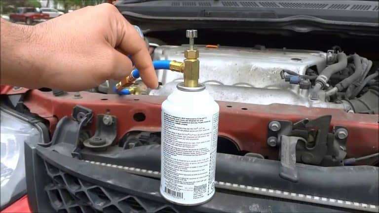
Refrigerant gas is the most useful product in this system. It refers to a gas used to pressurize the air conditioning system.
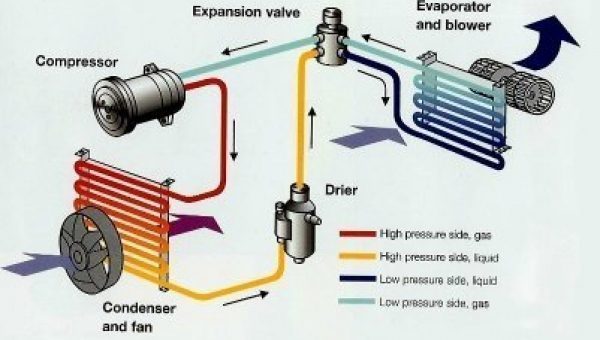
All air conditioning systems use similar components for the system to function. These are the compressor, the receiver-drier, the thermal expansion valve, the condenser, and the evaporator.
Find more details on each component discussed below.
1. Refrigerant
Although it is not a component of the car’s air conditioning system, it is the system’s lifeline. It is not possible to experience cooling comfort in your vehicle without the refrigerant.
At low temperature and pressure, it takes a gaseous form. Furthermore, it takes a liquid form when subjected to high pressures and temperatures.
Thus, this gas is essential and plays an important role in the air conditioning system. Every vehicle has a specified amount of refrigerant used to fill the system.
In passenger vehicles, it is typically about three or four pounds of refrigerant maximum.
2. The Compressor
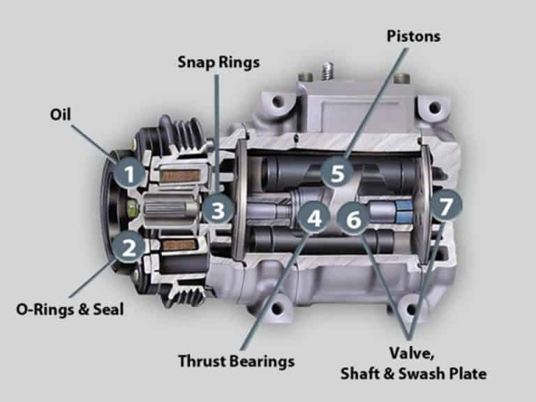
The compressor is an essential element of the car’s air conditioning system. It is a pump attached to the engine’s crankshaft, which drives it by giving it power.
Its main function, as its name suggests, is to compress the refrigerant. The refrigerant enters the compressor in a gaseous state and under low pressure.
When you turn on your air conditioner, you compress the vaporized or gaseous refrigerant in this component. The purpose of compression is to ensure it is under high pressure.
The pump drive forces the gas towards the condenser. Compressors can only compress gases and not liquids.
3. The Condenser
The main task of a condenser in this system is to condense the refrigerant from the compressor. Condensation occurs as a result of rapid cooling by hot or warm air.
The moisture or water vapor in the hot air forms a liquid state after condensation.
In the modern car air conditioning system, it is the most recognizable part.
At this stage, you transition the refrigerant from the gaseous state to the liquid form. You achieve this condensation by pressurizing the refrigerant.
The condenser cools the refrigerant with the air circulating around the tubes. The cooling process turns the gas into a liquid.
Thus, the refrigerant turns into a high-pressure fluid. At this point, it is ready to enter the next component.
4. Receiver-Drier
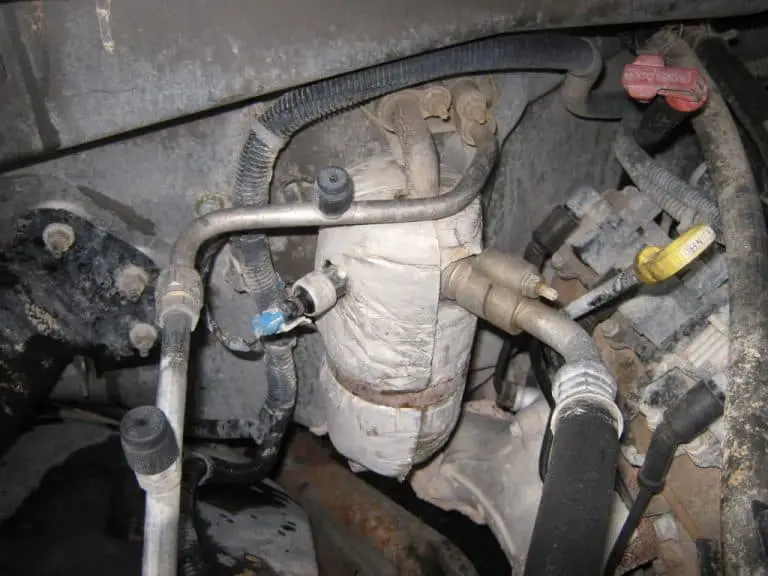
This component acts as a reservoir. It prepares the liquid for transfer to the evaporator. Yet, in this reservoir, there are desiccants, which is a drying agent. Desiccants are small granules that attract water.
Removing the water element at this stage is essential. If you do not remove it at this stage, it can turn into ice crystals.
These ice crystals are capable of damaging the entire air conditioning system. The desiccants at this stage remove all water elements, thus protecting the system as a whole.
The collapse of your vehicle’s air conditioning system can make your driving uncomfortable. Although you can open your windows during the hot season, it is not very helpful.
Windows can lead to excess wind when you drive fast, making you uncomfortable. Furthermore, it can let in undesirable substances such as dust.
5. Thermal Expansion Valve

In this valve, the expansion of the liquid occurs by changing the high pressure to low pressure. The expansion minimizes the pressure on the refrigerant.
As such, it further prepares the fluid before transferring it to the evaporator.
The valve’s design helps it detect pressure and regulate the refrigerant flow. This also allows for the regular operation of the system.
The moving parts of the valve can sometimes wear out, requiring replacement.
Furthermore, instead of using the valve in question, you can use an orifice tube. Yet, it performs the same task, which allows the expansion of the refrigerant.
This also reduces the pressure, before the refrigerant enters the next component.
Moreover, the orifice tube has no moving parts. It allows the refrigerant to flow at a constant rate.
But, over time, it gets clogged by debris. A system that uses an orifice tube turns off and restarts the system. It does this to control the refrigerant flow.
6. The Evaporator

The evaporator is the central part of the air conditioning system. Its location is in the cabin, on the passenger side.
All other AC components are located in the engine compartment. The evaporator has a similar design to a radiator.
But it is smaller and has tubes and fins. The design of these tubes and fins contributes to heat absorption.
When the refrigerant enters the evaporator coil, it freezes at zero degrees Celsius. The low temperatures are the reason why you must remove all water. Furthermore, the refrigerant enters the evaporator coil as a low-pressure fluid.
However, this refrigerant does not freeze at zero degrees. But its boiling point is relatively low; the heat from the passenger compartment is enough to boil the R-134a in this component.
After boiling, the R-134a changes to a gaseous state, which helps it absorb heat.
For vehicles that use the orifice tube system, it works differently. The system has an accumulator located between the compressor and the evaporator.
Sometimes this tube releases excess refrigerant to the evaporator.
The compressor can only compress gas and not liquid. Thus, the accumulator draws in the excess fluid before it enters the compressor.
Additionally, the evaporator absorbs moisture in the vehicle, thus giving you a cool feeling.
Dirt, moisture, and pollen condense on the evaporator coil. If water starts dripping under your car after stopping, it’s the AC evaporator.
Such drips should not worry you and your vehicle is in good condition.
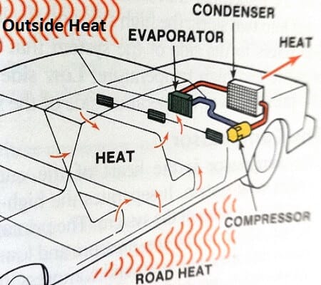
The Air Cooling Process in an AC System
This process begins at the vehicle’s air conditioning compressor. This is where the compression of the refrigerant into the high-pressure state occurs.
Compression causes the liquefaction of the refrigerant. It then heads to the condenser, through high-pressure lines.
The condenser allows the liquid to mix with the outside air. The mixture causes the atmosphere to absorb heat from the liquid.
Next, the fluid flows either into the orifice tube or the expansion valve. Here, it transforms into a gaseous form on the low-pressure side of the air conditioning system.
It then flows into the accumulator containing a desiccant bag. The bag collects unwanted moisture, among other impurities.
The clean refrigerant then flows into the evaporator through the tubing. In this state, it can collect heat from the air passing through the fins. This process leaves cooler air.
Conclusion
Finally, you now understand “how car air conditioning works”. All components work together by each contributing their part.
However, all elements are essential. If one part fails, the entire process collapses. Thus, you must ensure that every part is in good condition.
The car’s air conditioning system has three tasks to perform. First, cooling the car’s interior is very important, especially during the hot season. This ensures you have cool temperatures in your car.
Furthermore, heating the interiors during cold seasons is also important. You need heat in your car when it’s cold outside.
Finally, defrosting the windshield is the most crucial task of the air conditioning system. It is generally frustrating to keep struggling to see through your windshield.
As a result, it can affect your driving, leading to an accident.