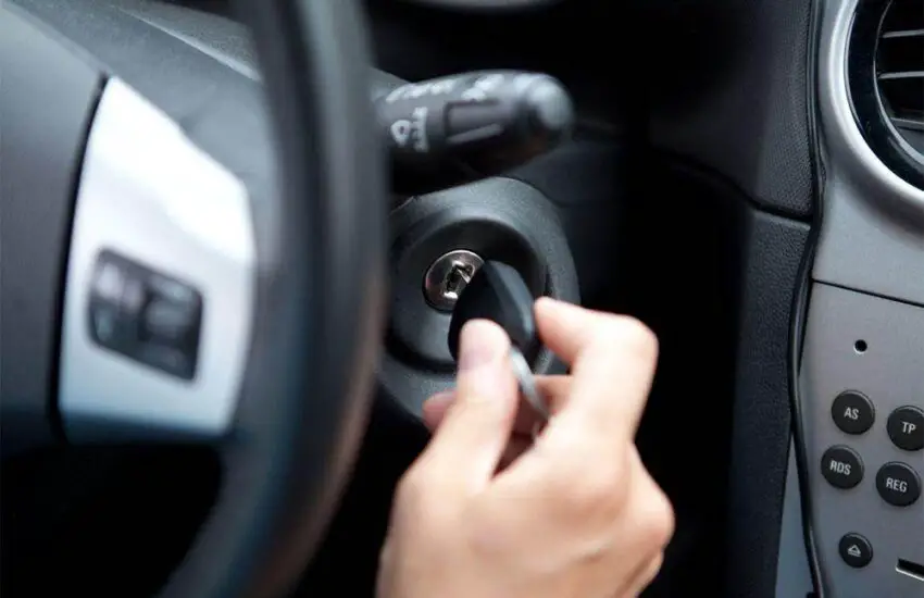
How to Test the Ignition Switch – Two Different Methods
A faulty ignition switch can cause many problems. It can lead to the shutdown of certain electrical components, the car not starting, or stalling immediately after starting. You may need to replace the switch if the problem becomes severe or if the car does not respond at all. But you need to know how to test the ignition switch to determine that it is actually broken and needs to be repaired.
Symptoms of a Faulty Ignition Switch
Know the symptoms before concluding that you need to replace the component or learning how to test the ignition switch. A faulty switch will display these signs to warn of a potential problem.
Sudden Vehicle Stalling
This is the main sign that the ignition key is failing. If the failure occurs while the engine is running, it can cut power to the ignition and fuel system, causing the car to stall.
The Car Stalls After Starting
This happens when the switch fails in the “ON” position. It may power the fuel and ignition systems when the engine starts but stops working immediately after.
A failing ignition system will show various signs. (Photo source: Honda-Tech)
Problem Powering Accessories
Turning the key to the “ACC” position should power the accessories. If this does not happen, there must be a problem.
How to Test the Ignition Switch: The Procedure
The function of this component is to provide voltage to the ignition control module and the ignition coil. The ignition system has two wires connected to the switch’s operating terminal. One goes into the module and the other connects to the primary resistance and the coil. The switch’s start terminal also has a wire connection to the module.
To inspect the ignition switch, it must be removed from its location and the resistance and continuity checked along all terminals. Before removal, it is necessary to check if the connections to the switch are working. You can check the switch’s voltage using two tools: a 12-volt test light or a digital multimeter.
How to Test the Ignition Switch with a Test Light
Step 1: Disconnect the wire connector from the module after turning off the ignition. Also disconnect the S terminal from the starter solenoid. This will prevent the engine from starting even if you turn the ignition key to the ON position.
Step 2: Turn the ignition key and place it in the ON position. Probe the red wire connection to test for voltage. Do the same at the ignition coil’s battery terminal.
Step 3: Next, turn the switch to the start position and probe the white wire connector from the module and the ignition coil’s battery terminal to check for voltage.
The circuit and switch are faulty if there is no voltage.
Using a multimeter is hassle-free. (Photo source: mightyguide)
How to Test the Ignition Switch with a Multimeter
Turn the ignition key to the OFF position. Use the multimeter’s positive lead to probe the module’s power wire. The negative lead should go to a good ground on the distributor base.
Now, turn the key to the ON position and measure the voltage with the meter. Anything less than 90% of the battery voltage indicates a problem with the ignition system.
How to Reset the Car Computer at Home
The car computer, also known as the ECU (Electronic Control Unit), is designed to monitor your vehicle’s engine system. It keeps track of tolerance changes in the engine’s actuators and sensors while you drive. All information is stored in the RAM, backed up by the car battery. Every time you start the car, the ECU reads the last recorded values instead of starting from scratch. However, sometimes it may falter, and you might wonder how to reset the car computer without consulting a professional.
Here, we will provide you with some maintenance tips to resolve your car computer issues.
Symptoms of a Bad Car Computer
The car computer is usually located in the engine compartment or under the dashboard and communicates with other vehicle systems via a network of sensors, actuators, and other electronic components. The computer uses this data to make real-time adjustments to the car’s performance, such as adjusting the fuel/air ratio, ignition timing, and other critical parameters. When your car computer fails, it will display a long list of symptoms that make driving your car difficult. Let’s explore some common signs below:
Check Engine Light Warning
Usually, the check engine light comes on at the first sign of a problem. The simplest symptom to recognize the condition of your car computer is when the check engine light illuminates on your car’s dashboard. This sign may indicate an issue with the car computer. The check engine light can be triggered by a number of problems, including issues with sensors, wiring, or other computer components.
Engine Performance Issues
A faulty car computer can lead to poor engine performance, resulting in rough idling, stalling, or difficulty starting. The engine may also experience a loss of power or reduced fuel efficiency.
Transmission Problems
A defective car computer can also affect the transmission, causing issues such as delayed shifting, harsh shifting, or transmission slipping.
Failed Emissions Test
If the car fails an emissions test, it could be a sign of a problem with the car computer. The computer is responsible for managing the car’s emissions, so a faulty computer can cause the car to produce more pollutants than it should.
Electrical Issues
A faulty car computer can also cause electrical problems throughout the vehicle, such as malfunctioning headlights, power windows that won’t go up or down, or issues with the car’s audio system.
How to Reset the Car Computer? The Steps
If your car’s check engine light remains on even after the engine has been repaired, you may need to clear the error codes to turn off the dashboard lights. This requires you to reset the car computer to resolve the issue. You would need equipment including a battery wrench, a 10-watt resistor, and a cable or electrical tape.
Please follow the steps mentioned below to reset your car computer.
1. Turn Off the Battery
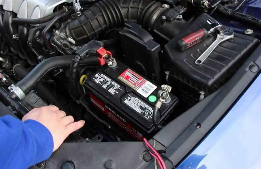
The first step is to turn off the car. Then, remove both battery terminals using the battery wrench and remove the battery from the compartment. This ensures no power is flowing while you reset the car computer and also allows you to perform battery maintenance. You can also consult a professional on how to reset the car computer.
Secrets on how to reset the car computer. (Photo: Tesla)
2. Handling the Battery Wires
Once both terminals are removed from the battery, make sure to couple the negative and positive wires connected to the engine. Then, tie them together with a cable or electrical tape.
3. Perform a Software Reset
The software reset to factory settings involves cutting power to the computer and draining any residual current that may be inside the capacitor circuit. Once the computer loses all power, it will lose any remaining memory. In most cases, this would be error codes, which would also be erased. This is an important step when you reset the car computer.
4. The Car Battery
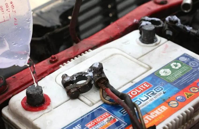
Meanwhile, it’s a good idea to inspect the car battery while the circuit power is drained. Use baking soda or water to clean the battery and its terminals. This will help you reset the car computer in less time.
5. The 45-Minute Wait Time
After a period of 45 minutes, reconnect the battery and its terminals as they were. Make sure to check the polarity of the terminals. You can also use these steps to reset the car’s air conditioning system.
6. Final Step
Start your car, and the error codes will have been cleared, and the issue resolved.
Things to avoid when resetting the car computer. (Photo: RADU BERCAN/123RF)
Resetting a car computer can be a useful troubleshooting step to resolve certain issues with a vehicle, such as a Check Engine light or performance problems. To reset the car computer, a common method is to disconnect the battery for a few minutes, which will clear all stored data and reset the computer’s memory. Another method is to use an OBD-II scanner or diagnostic tool to clear any diagnostic codes that may be stored in the computer.
It is important to note that resetting the car computer alone may not resolve the underlying issue causing the problem, and it is always recommended to have a qualified mechanic diagnose and repair any issues with the vehicle. Additionally, resetting the car computer may clear certain settings or preferences, such as radio presets or climate control settings, which will need to be reconfigured after the reset.
Next time you encounter an issue with the engine lights staying on, remember these tips on how to reset the car computer, as they will surely resolve the problem.
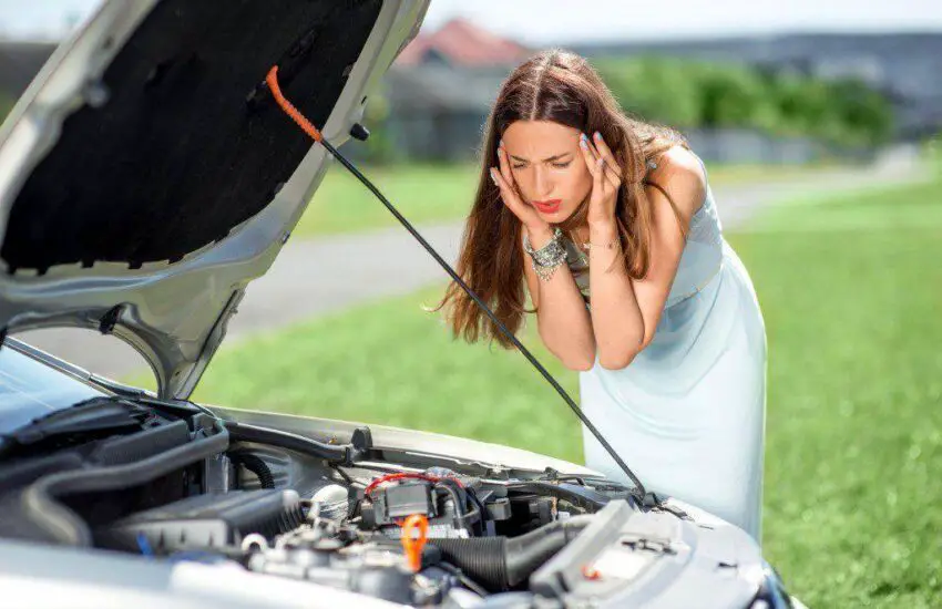
What happens if the car battery fails while driving
There’s nothing more thrilling than when your car starts giving you trouble while you’re driving. A small issue is fine, but what happens if your car battery dies while driving?
By “car battery dies,” we mean the battery discharges beyond the point where it has enough power to operate the car.
The list of problems that can drain your battery is endless. Some of the most common reasons include faulty alternator diodes, charging issues, persistent electrical leaks, loose or corroded battery connections, and even extreme weather conditions.
Now let’s explore exactly what happens when your car battery dies while driving.
Problems Encountered When Your Car Battery Dies While Driving
Problems encountered when the car battery died while driving. (Photo: YouTube)
Even if you buy the best car batteries on the market, there’s always a risk that your car batteries will die. This is due to various reasons. Some of them can be resolved easily while others may require a visit to the mechanic.
But what happens if the battery dies while driving due to a faulty alternator? Things can gradually worsen until you slowly stop on the side of the road. You might notice the lights are dimmed and the cabin ventilation fan is running slower.
Furthermore, when your car battery runs out while driving, you don’t have enough power to operate the spark plugs or injectors because the parasitic load of the electrical system drains it further.
Eventually, the car will stop running properly and all the dashboard lights will start flashing. That’s when you’ll pull your car over to the side of the road and ask for help.
Well, batteries don’t die immediately; they get sick at first, then sicker and sicker. But most people don’t notice the signs. Slowly and steadily, the car turns over slower at startup or the headlights dim more when sitting at a light.
It’s important to know that a car dies even with a gradually weakening battery and a good alternator. This usually happens when dying car batteries place a huge load on the alternator, thus destroying it.
What to Do When Your Car Battery Dies While Driving
So what happens if your battery dies while driving? Here’s what you can do if your car battery dies while driving:
Restart Your Car
The best thing to do in such situations is to restart your car. First, remove the key from the ignition, give your car a few seconds of rest, and start it. If your car starts, that’s great, but if not, you need to go to a repair shop to fix the problem.
Try to Jumpstart Your Car
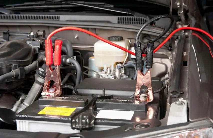
If it doesn’t restart, you might need to take a big step forward to get home. Plug in your portable jump starter and start charging your battery gently.
This charge won’t last long because the alternator is dead. The goal is for you to have enough power to get home safely and continue from there.
If you’re still far from home, ask people who wouldn’t mind helping you jumpstart your car. Because a dead alternator won’t replenish your battery, you can only use the amount of power created by the jump.
Try Calling for Help
Problems caused by the car battery dying while driving. (Photo: Consumer Safety Guide)
Most people don’t prepare much for this situation; you should always keep this question in mind: can a car battery die while driving? And then you’ll have a specific step to solve this problem yourself.
First, take a deep breath and don’t panic. Driving with a dead battery is risky. Keep your cool and proceed with caution at all times. Then, try to get help from someone who can tow your car to a repair shop.
Furthermore, you can call roadside assistance. A specialist from a repair company is always available to help you. Sometimes, expert advice on car maintenance is available.
However, keep in mind that you need to find a solution to the problem as quickly as possible.
Turn On Your Hazard Lights
Don’t forget to turn on your hazard lights because your safety is the most important thing. Let other drivers give you and your vehicle some space by activating your hazard lights.
FAQ on Car Battery Death
When should you replace your car battery?
It’s essential to understand if a car battery needs to be changed. Don’t wait until the battery is depleted. If your car battery is depleted, you can replace it.
How can you tell if your vehicle’s battery is too old?
All car batteries have a specified lifespan. However, there may be differences between some units.
Read the printed code or take a look at the label to determine a battery’s age. The date it left the factory could potentially be the date the code was produced.
How long do most car batteries last?
Between three and four years
Batteries in some automobiles can last up to five or six years, while others need to be replaced after just two years.
Generally, your car battery should be replaced every three to four years. Routine maintenance also includes replacing your automobile’s battery.
What’s the fastest way to drain a car battery?
Increasing the heating or air conditioning while driving consumes more power from the battery. Controlling the cabin temperature and the battery is the one that consumes the most electricity, just behind operating the car.
Electric vehicles, unlike ICE vehicles, cannot extract heat from the engine to warm the interior.
Watch this video from Nathans BMW Workshop to learn more about the most common causes of battery drain and solutions for all cars!
Stereo components (subwoofers), phone chargers, and anything you leave connected to the vehicle’s sockets that continue to be powered by the battery after the car is turned off can drain your car battery over time.
Interior and under-vehicle LED lighting is also a source of power consumption. Loose or rusty connections.
Thus, your car battery died while driving for many different reasons. It’s important to have it checked either by yourself or by a quality service workshop.
You can follow some maintenance tips given by automotive experts to handle this situation with ease!
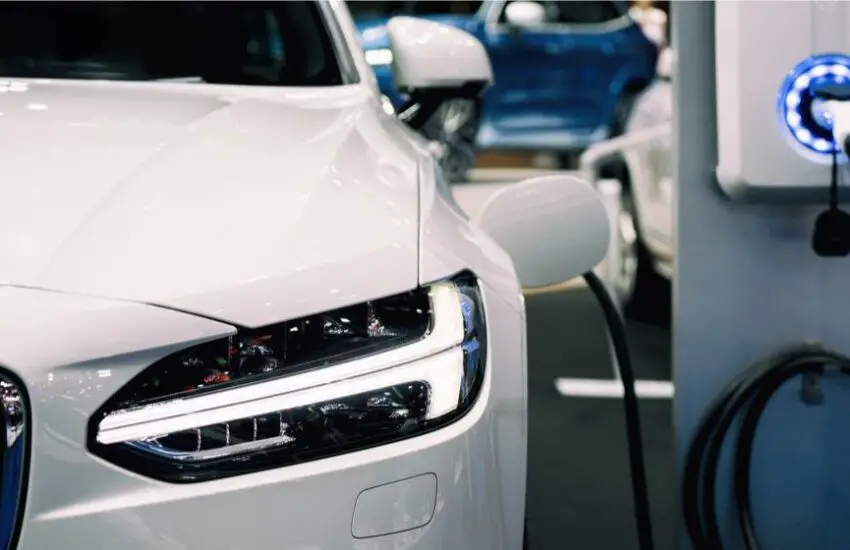
The Hidden Costs of Owning an Electric Car
Before saying goodbye to gas stations, discover the hidden costs of owning an electric car to prepare yourself well for new road routes!
In an era where gasoline prices are soaring and electric vehicle (EV) charging costs are significantly reduced by manufacturers, buying an EV is probably an obvious choice. But the economics of electric vehicles is a complicated story, and you need to understand many unknown issues before deciding to say goodbye to gas stations.
Hidden Costs Associated with Owning an Electric Car
Buying a New Electric Car
To drive an electric vehicle, you first need to buy the car, and it’s not cheap. Even if you sell your existing gasoline car, you will likely have to shell out at least $10,000 more. This decision will take many years to reach the break-even point, even if you just buy a very cheap electric vehicle, live in a place with low electricity prices, and always charge your car at home. Too many “ifs” make buying an electric car difficult to consider as an economical option.
In reality, many people buy hybrid or other fuel-efficient vehicles at a net cost much higher than what they could save on fuel when using them.
Of course, a fully electric car will save you much more energy than a hybrid car, but its initial purchase price, along with insurance and repair costs, can lead to less positive economic outcomes. On the other hand, traditional gasoline cars often involve many minor maintenance costs that electric vehicles don’t have, such as oil changes or brakes.
Many people even give the reason for buying an electric vehicle to protect the environment. This goes beyond the scope of the article, but you might think of ways to protect the environment much more effectively than investing money in electric cars.
Resale Value
Price depreciation happens with any vehicle you buy and is a very important factor to consider for electric vehicles. The value of a new car will always decrease once you drive it home, leading to generally higher per-mile costs for electric vehicles due to the selling cost. And it wasn’t cheap, and the price drop rate has been faster than that of traditional cars.
For example, Subaru, even though not renowned for its electric vehicles, has an average resale value of 66% of its new price after five years of use. Assuming a new Subaru costs $35,000, this price drop will cost you $11,500 over the first five years, which is $6.3 per day.
Meanwhile, a Tesla with a higher average price will retain 58% of its value after 5 years (this is why Tesla ranks 3rd on the list of luxury car brands). In other words, if you buy a Model 3 for $60,000, you’ll have to accept a “loss” of $25,000 over the first 5 years, which is $13.8 per day.
Ultimately, most people know that as soon as you drive a new car off the lot, it loses value. This loss is also amplified when it comes to electric cars. Here are some reasons why electric vehicles depreciate over the years:
New electric cars benefit from a tax credit of over $7,000 (with some limitations). For example, once this tax credit is canceled, the value of a car can drop by up to 60% at the end of a three-year lease.
Electric vehicles lose up to 20% of their maximum range after 5 years.
Electric car technology is still new and evolving rapidly. Like the latest smartphone compared to a three-year-old model, new EV models will be much more attractive to buyers than older models, especially as battery technology improves.
The value of a new electric car will always decrease once you drive it home. (Photo: Johner Images)
Battery Replacement
Another form of depreciation that only occurs with electric vehicles is that after a period of use, the battery needs to be replaced. Unlike a traditional car, which has a non-replaceable engine, the EV’s battery must be replaced when the vehicle operates to a certain point and can no longer maintain the original range. Battery replacement costs vary by vehicle, but the average estimate is around $10,000.
However, this figure is just an estimate, as very few EV models have been in operation long enough for the battery to degrade to the replacement point, and the replacement battery market is not as crowded as the traditional automotive parts market.
Overall, unlike standard car batteries, electric car batteries are not cheap. They perform well for 100,000 miles but cost between $10,000 and $20,000. Furthermore, EV battery technology will improve over the next few years, and their prices are expected to drop. But if you want to increase the mileage, you need to think about how you will pay for a new battery. Certain conditions can lead to faster degradation of an electric car’s battery.
For example, using ultra-fast DC charging will reduce the battery’s lifespan. Kia also notes that fast charging leads to a 10% decrease in battery life over 8 years.
Additionally, for electric vehicles that are bought and sold over and over, we don’t know who will be responsible for battery replacement. If you buy a used electric vehicle, expect that you will be the owner and will have to spend your own money to replace the car’s battery once its range decreases, thus making the car’s depreciation problem even more challenging.
Registration Fees/Gas Tax
The gas tax, which is levied at the pump in some states when refueling a gasoline vehicle, is used to help pay for road repairs. Since electric vehicles don’t use gasoline, states impose additional registration fees of about $50 to $200 for electric vehicles. Currently, Georgia has the highest electric vehicle fees, but check the full list of states and electric vehicle registration fees for more information.
Insurance Premium
Most car insurance companies charge higher fees for electric cars because their repair and replacement cost more, and fewer repair shops have staff trained on electric vehicles. As a result, you will pay between 5% and 20% more for electric car insurance than for a gasoline car.
Roadside Charging Stations
Even though it’s certainly cheaper to charge an electric car than to pay for a gasoline car, your actual savings will be significantly lower if you charge it on the road rather than at home. The price of public charging facilities varies considerably, some charging by minutes of charging and others by kWh of electricity used. Although DC fast chargers can cover 100 miles in 10 minutes, they are also the most expensive public charging option. However, convenience and charging time are also factors to consider.
Home Charging Source
Although it is by far the cheapest charging method, home charging for electric cars also has drawbacks. It may be less expensive to charge the electric vehicle with a Level 1 charger using a standard 120-volt outlet, but this option is not practical if you drive daily, as this type of charging can take 24 to 36 hours in cold climates. This means daily commuters need a more expensive Level 2 electric car charger installed by a professional for convenient overnight charging.
EV chargers typically cost around $2,500 for the charger and installation, and EV chargers have a lifespan of about ten years. If your home needs an electrical upgrade to accommodate a Level 2 charger, you will have to pay extra.
Range Loss (Battery Performance)
As mentioned above, electric vehicle batteries degrade over time. So, as your car ages, a fully charged battery will allow you to travel shorter distances than before. Additionally, cold weather affects the performance of EV batteries.
Repair Cost
Electric vehicles have much more complex electrical systems than traditional gasoline vehicles. And these systems are often very expensive to repair or replace. Furthermore, electric cars often have parts that are hard to find and replace, which can also increase the actual cost of owning an electric vehicle.
On average, over a three-month period, repairing an electric vehicle costs twice as much as repairing a gasoline car. Over a year, the cost of an EV service would still be more than double the cost of an ordinary vehicle repair. The average repair cost for an electric vehicle is about $300 per electric vehicle, while a gasoline vehicle with an internal combustion engine costs an average of about $150.
Another important factor in electric vehicle repair costs and the true total cost of owning an electric vehicle is the maintenance of the EV battery. Most other electric vehicles run on lithium-ion batteries. They are similar to the batteries in your phone or laptop but are much larger. Lithium-ion batteries degrade over time, and the lifespan of EV batteries is typically 10 to 15 years.
Another hidden cost associated with owning an electric car is the cost of spare parts. Electric vehicles often have parts that are hard to find and replace, which can increase the cost of ownership.
Electric vehicles often have parts that are hard to find and replace, which can increase the cost of ownership. (Photo: Monty Rakusen)
Furthermore, many auto repair shops have mechanics who are not familiar with electric cars for obvious reasons. This means it will take mechanics more time to diagnose and then fix the electric vehicle’s problem, thus adding more dollars to your car repair bill.
Buying an Electric Car Is Not Easy
Thus, the cost of purchasing and using an electric vehicle is much higher and fluctuates depending on where you live or how much you have to pay for electricity.
For example, in California, the average cost of electricity is 18 cents/kWh, while in Idaho, it’s 8 cents/kWh, and in Hawaii, it’s 28 cents/kWh. Additionally, the electricity bill is not always clear. Everyone knows that there are times of the day when electricity prices will be lower than usual, and don’t forget the associated taxes.
A quick comparison on the U.S. Environmental Protection Agency website shows that the Tesla Model 3 Long Range consumes much less energy than the BMW 330i xDrive (gasoline car), suggesting that Tesla seems to be a great option if you want to save money. But a 2021 study by the Anderson Economic Group concludes that driving an electric car can cost much more than driving a traditional car.
Driving an electric car can be either cheaper, as expensive, or more expensive than driving a gasoline car. An electric car actually helps reduce travel expenses, except for longer trips. The shift to electric vehicles is inevitable for technological, political, and financial reasons, but what you need to know is whether the cost of using an electric vehicle suits your situation and economic condition. How you use electric vehicles will help protect the environment.
Are Electric Cars Worth Owning?
It is currently too difficult to answer this question because there are too few electric vehicles on the streets. Even though electric vehicles have clearly made a breakthrough in the local automotive industry, there is still too much work to be done. When the time comes, electric cars will certainly become cheaper than gasoline and diesel cars.
Conclusion
We have just scrolled through some information about the hidden costs associated with owning an electric car with our article above. We hope to see you again with more insightful car maintenance tips!
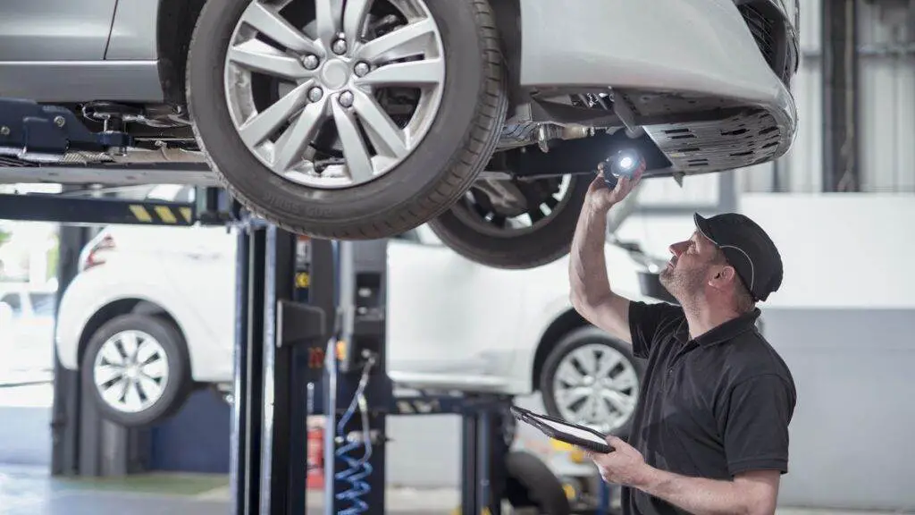
Reasons Why Your Alternator Isn’t Charging the Battery and How to Fix It
Have you ever noticed signs that your car battery is weak or failing to charge, even if it’s a new battery? Could the alternator be the cause or not? Let’s go through this guide to discover the common reasons why your alternator is not charging the battery and the simple steps to fix this issue.
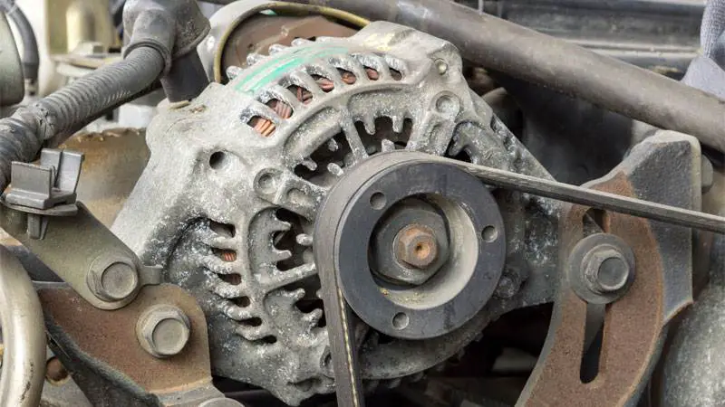
The Main Functions of a Car Alternator
The alternator is one of the 5 main components of the car’s electrical system, functioning as a machine that generates energy to power the battery, serving the operation of charging devices and electrical equipment.
Car alternators produce electricity by converting mechanical energy. Notably, the source of mechanical energy can come from internal combustion engines, solar energy… If you tried to start your vehicle without an alternator, the battery alone would not be able to produce enough energy to turn your engine over even if you have a new car battery. The alternator is necessary to keep the battery charged and alternate the electrical current through many components of your car.
A faulty car alternator will affect the charging process and the operation of the battery. At the same time, the car’s electrical equipment also operates abnormally and cannot function at its maximum capacity. So why is my alternator not charging my battery? Let’s find out the causes in the next part:
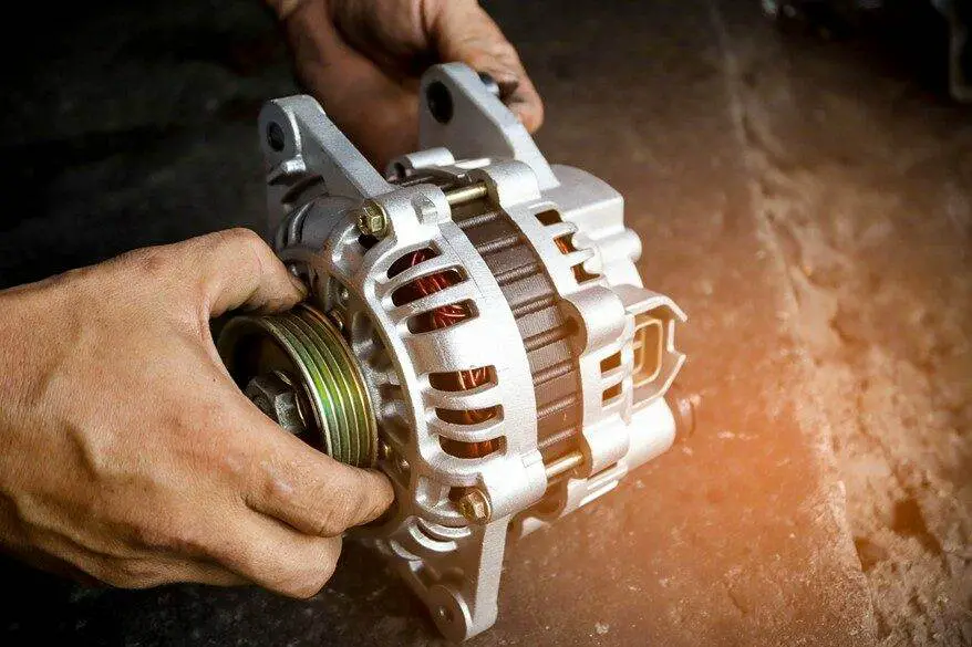
Without an alternator, the battery alone would not be able to produce enough energy to turn your engine (Photo: nationwide.com)
Alternator Not Charging the Battery: 6 Common Reasons
If the car’s alternator stops charging your battery, it’s as if your car cannot start. However, if you are lucky enough, in some situations, your car will probably run for about 10 minutes, but after that, the current will be immediately cut off. Knowing the reasons will help you diagnose the exact problem and possibly fix it.
Generally, a common cause for the alternator not charging is minor wear or corrosion. Practically all mechanical failures, whether it’s brush wear or bearing failure, are the result of an extended lifespan. Modern alternators are equipped with sealed (maintenance-free) bearings that only need to be replaced after a certain time or mileage. The same goes for the electrical part: often, the entire device must be replaced. Besides these causes, other reasons can be considered and checked:
1. Blown Fuse
Some models have alternators that depend on a particular fuse to function. However, sometimes this fuse can blow due to a power surge or simply due to old age. At that moment, your alternator will no longer charge the battery. But remember that not all have fuses, so you must consult the owner’s manual to see if your alternator needs fuses or not. After that, we will give the exact diagnosis.
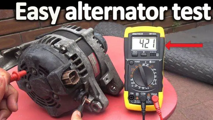
2. Bad Alternator
Another common issue could be that the alternator is not working or is poorly connected. To test this, you can apply a multimeter in Voltage mode. Start your car and then use a multimeter to check the car battery voltage. The normal number should be around 13 to 14.5 volts. If it’s lower, try revving the engine a few times to see if the voltage increases or remains low. If the Voltage does not exceed 12.5 Volts, the battery will not be charged and the alternator will not work.
A good alternator correctly designed for your engine will provide the charging voltage as described even at idle, even if it may drop below 13 V.
3. Bad Alternator Brush
Carbon brushes constitute only a small part of the alternator but play an important role. Because it is a conductive material and it is responsible for transmitting electricity, connecting the electricity from the static part (Stator) to the rotating part (Rotor).
When the alternator brush is damaged, the electromagnetic connection between the two parts above will be interrupted. Carbon brushes often encounter problems such as oxidation due to long-term use. Carbon brushes are worn out and the brush springs are broken.
4. Stator Winding Problems
The stator coil is made of a core and a coil placed in the front frame. It is responsible for generating a three-phase alternating current through the variation of the magnetic flux of the rotating rotor. When this part is broken or grounded, electricity will not be produced and the power generation will not be able to supply energy to many systems.
5. Alternator Rotor
The rotor is a magnet inside the stator coil. It is responsible for creating a variable magnetic field inside the stator coil. The magnetic field creates an interaction with the stator winding and generates electricity. When the rotor coil is damaged, the magnetic field is not created and no current is generated, which affects other functions of the car.
6. Regulator
As its name suggests, the regulator is responsible for regulating the voltage of the current emitted by the generator system to keep it always stable. If this part is damaged, the electrical current will be weak and strong, causing other parts of the vehicle to flicker such as the lighting system and the car starter.
Symptoms of a Bad Alternator
If you detect any of the symptoms below, you should have your alternator checked:
Difficulty Starting
If you turn the key to start but the engine cranks weakly and starting takes a long time, it could be due to a faulty alternator, which prevents the battery from charging and the voltage is not sufficient to start the engine. Quickly taking your car to a trusted mechanic to have it checked is the safe method. In this case, you should also turn off some electrical equipment like the air conditioning, radio, or headlights to save energy.
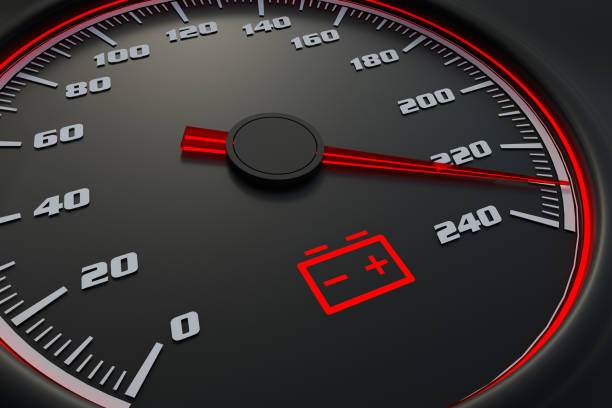
The Battery Light Turns On
Normally, when starting the engine, the battery light turns off to inform the system of normal operation. But when the car is running and the battery light is still on, it could be due to a weak, damaged battery, or a problem with the battery charging system. The light is on to signal this malfunction.
When you are driving and the battery light is still on, it could be due to a weak battery (Photo: istockphoto.com)
Dim Headlights
Because the alternator powers the vehicle’s accessories, the lighting system, etc. When this part has a problem, the headlight system will be weak, dim, and flicker. Therefore, if the car lights are weaker than usual and flicker, it is a sign that you have a faulty alternator.
Strange Smell
This smell could be due to the wire heating up because the moving pulley is not aligned or not rotating freely. From there, a significant friction force is created on the belt and that part of the belt heats up, creating an unpleasant smell of burnt rubber. And then, the car’s alternator can be broken.
The alternator is an important component that allows the battery to be charged and powers all the car’s electrical devices. If this device has a problem, it will greatly affect the operation and movement of the vehicle. Knowing how to check a car generator will help drivers know its condition so they can handle it promptly.
But testing the alternator is a rather complex process, it requires experienced technical personnel and the help of different types of tools to know the exact cause. However, if you have basics in the automotive industry, you can perform this procedure entirely by yourself:
How to Test a Car Alternator?
The alternator is not charging the battery but the alternator is good. What should we do? (Photo: pinterest.com)
To check the alternator, you need to prepare a professional test kit and a voltmeter.
Follow these 3 steps to test your alternator:
Step 1: Test the Battery
To check the battery, we use a voltmeter. Attach the red wire of the voltmeter to the positive terminal of the battery and attach the black terminal of the voltmeter to the negative terminal of the battery. Then read the settings.
If the voltage is above 12V, we can proceed to the next step. Conversely, if it is below 12V, you need to charge the battery and re-measure the voltage after charging.
Step 2: Start the Car
After measuring the battery voltage, press the accelerator to let the engine run. You need to increase the accelerator to a speed of 2,000 rpm to let the engine warm up after a long period of inactivity.
Step 3: Let the Engine Run Steadily and Check the Battery Voltage.
Let the engine run steadily and check the battery voltage. Continue reading the voltmeter value. If the car battery voltage is between 13 and 14.5 V, the alternator is functioning normally.
If the voltage value is lower or exceeds the threshold of 13 to 14.5 V, it means the generator is faulty or has a problem. Furthermore, it is necessary to continue checking the operation of electricity-consuming devices like air conditioners, lights… to see if they are working normally.
How to Fix an Alternator That Is Not Charging
Upon detecting signs of damage on the vehicle, the recommended method to remedy this situation is to take the vehicle to a repair garage so that technical staff can perform an inspection, detect the right ailment, and treat it with the right medicine.
In the case where the car breaks down in the middle of the road, or if it is suspected that the alternator is damaged, causing the battery to discharge and making it impossible to start the engine and drive, you can call roadside assistance for help or test the battery regulation yourself if possible.
Additionally, you should also maintain the electrical system as well as the alternator regularly, periodically every 3,000 km – 5,000 km of operation (equivalent to about 3 to 6 months) to increase longevity and limit and detect generator damage as soon as possible.
How to Keep Your Car’s Alternator in Good Condition
Mastering the following tips will help drivers maintain their car’s alternator in ideal operating conditions. Specifically:
Regular Maintenance: during regular maintenance, all parts of the vehicle will be checked. If the alternator has a problem, it will be promptly maintained/repaired to avoid serious damage.
Limit the Use of Multiple Electrical Systems at the Same Time: Using multiple electrical loads at the same time will cause the alternator to operate less stably. Therefore, this must be limited to maintain the operation and durability of the car’s alternator.
Replace the Belt at the Right Time: One of the keys to extending the alternator’s lifespan is checking the belt. As it is made of rubber, the belt frays and cracks over time, typically between 40,000 and 70,000 miles – although there is no precise schedule. That’s why it’s important to check the belt during routine maintenance. Replace it after noticing the first signs of aging as it can damage your engine.
New Alternator Not Charging the Battery: Learn More About the Repair Process
So, in this section, we have provided you with information related to the alternator not charging the battery and how to fix this issue. At the same time, you should apply tips to keep this part in the best condition. So we hope all this information will be useful to you in one way or another if you encounter the same problem with the car alternator.
How to Test a Car Battery
The battery is a very important component of a car. Regular battery testing can ensure it’s ready to start your vehicle under all conditions. Your vehicle’s entire system depends on it and proper maintenance. To keep your best car battery in perfect condition, it’s essential to know how to test a car battery. If you haven’t tried it before, don’t worry. Here, we will present 6 amazing ways to do it.
How to Test a Car Battery in 6 Interesting Ways
Regularly testing the car’s batteries and electrical systems helps your car function correctly and reduces the risk of breakdowns. Here are the 6 most common ways to check your car battery.
#1. Voltmeter
A voltmeter is necessary to perform this trick. (Photo: sageGEEK)
To understand how to test a car battery, knowing how to use a voltmeter is very important. There are 2 types of voltmeters you can select to test your battery. One is analog and the other is a digital voltmeter. The best solution is to choose a digital voltmeter, as it is easier to read and gives you a precise measurement. However, there are certain things drivers should know:
First, carefully check your car’s ignition before the procedure. Ensure the car’s ignition key and all lights are turned off. Second, car owners must remove the cover from the battery’s positive terminals, check these terminals, and clean them properly. Third, always remember that the voltmeter’s positive wire must be connected to the battery’s positive terminal, which is red. Meanwhile, the voltmeter’s negative wire is connected to your battery’s negative terminal, which is mostly black. Fourth, after completing these parts, you can see that the voltmeter will display results based on the battery’s condition. Volts from 12.4 to 12.7 indicated that the vehicle’s battery was in good condition.
In the voltmeter result, when you see a value lower than 12.4 volts, it means your battery is weak and needs to be recharged to improve. If the value is below 12.2, slowly charge your battery and check again following the same steps. On the other hand, if the value is above 12.9, it indicates your battery has an overvoltage. So try turning on the high beams to remove the excessive voltage charge.
To learn more, watch this video on how to check a car battery with a voltmeter or multimeter.
#2. Ammeter
The ammeter is normally used to measure any flow. In many vehicles, the ammeter is pre-installed, which is very helpful and useful.
It tells you the battery’s charge status. This meter also informs whether the charge is entering or leaving the battery. This lets you know if the alternator is charging the battery or not, due to the heavy load. It will give an accurate indication of the battery’s good condition. If the charge is ridiculously low, you will then be sure the battery is weakening. When learning how to test a car battery, drivers need this tool because it gives much faster results than a voltmeter.
Watch the video explaining how to use an ammeter to test your car battery.
#3. Battery Health Indicator
The battery health indicator is usually pre-installed in many vehicles. If you want to know how to test a car battery, this is one of the most important devices. Old cars don’t have it installed, but it can be installed if you wish.
The round glass cover indicates the battery’s condition, and based on this, you can maintain your battery.
By turning on the ignition, the arrow will point near the division between the red and green bands. When the circle is green in color, your battery is in good health. The red circle indicates your battery is operating with a lower charge and needs to be given a proper charge to function normally.
When you see dark black or clear color, it means the battery is depleted or discharged and you need to replace it quickly.
Testing will be much easier with the Power Probe test. (Photo: Amazon)
A power probe test device is a faster way to know how to test a car battery. It’s a simpler way to test a car battery than a voltmeter:
To start, drivers must remove the cover from the battery’s positive terminals. After that, the device’s positive wire connects to your battery’s positive terminal. Then, connect the Power Probe’s negative wire to the negative terminal. The probe’s tip is then attached to the battery’s positive terminal. Finally and most importantly, if the battery is below 12.2 or above 12.9, we recommend following the steps mentioned above in the voltmeter method. Areas where the weather is mostly cold will be particularly beneficial for the power probe.
You can have a clearer view of how to test the car battery with Power Probe by watching the video below.
#5. A Hydrometer Check
The powerful device for testing a car battery. (Photo: YouTube)
A fluid device for measuring the battery is known as a hydrometer. This is used to measure the battery’s specific gravity to determine its state of charge. It also determines the strength or weakness of the battery acid or fluid. However, this method is useless for knowing your battery’s capacity.
Generally, a fully charged battery, when tested by a hydrometer, should have a specific gravity between 1.265 and 1.299 at 80°F (26.7°C). Use the manufacturer’s specifications for your specific battery to determine the acceptable range of specific gravity readings. If the readings are below the acceptable range, it may indicate a weak or discharged battery.
Capacity depends on the number of plates present in each cell. If any of these plates are damaged, the cell’s capacity is affected. For a sealed battery, this method might not work.
However, please note that testing a car battery with a hydrometer provides a general indication of the battery’s health status. For a more accurate assessment, you might consider using a battery load tester or consulting a professional mechanic.
#6. How to Test a Car Battery with a Battery Load Tester
You must check that the terminal is disconnected from the battery. The positive fine gauge of a battery load tester must be connected to the battery’s positive output.
Later, the negative wire will need to be connected to the negative output. Keep in mind that some battery cable testers don’t have a negative output, but there is a pin connector on the other side of the tool. You must touch the car battery’s negative output if you have a pin connector. The tool will not work for more than 5 seconds and later, it will connect to a car battery. There will be sparks when the car battery touches the pin connector. This means everything is going as it should.
The voltage rate will drop to 10-10.5 V if the battery is in good condition. The voltage drops to 9 V, meaning you will soon need to replace the battery with a new one.
Conclusion
Here are the 6 most useful ways to test a car battery for you. Perform regular checks on your car battery to avoid any problems and also to extend your car battery’s lifespan. Let us know if these techniques work for you.
How to Recondition a Car Battery in 5 Steps
A car battery is one of the most expensive pieces of equipment that you want to keep in the best condition for a long time. A bad battery replacement can be costly, but not when you have an effective DIY guide on how to recondition a car battery solution. Yes, you read that right! You can easily recondition your car battery with our foolproof method. So first, let’s find out what car battery reconditioning is!
What Are Reconditioned Car Batteries?
Reconditioned car batteries refer to the process of restoring the healthy life and charging capacity of your old and dead cells. It would be a total waste to easily throw away your old batteries when you can still recondition them one to three times.
So, instead of throwing away the batteries. Let’s learn how to recondition a car battery at home. You will be able to learn it in the next section of our article.
Why Should You Recondition Batteries?
What we always see are people throwing away their car batteries. It’s understandable since no one wants the hassle and inconvenience associated with using batteries that are no longer effective. Likewise, drivers have no idea how to recondition batteries. Batteries are also incredibly expensive to replace, and their price might not even go down as the device ages.
Battery reconditioning allows you to preserve and refresh the function of your batteries so they can perform as before: giving you enough charge and saving you a lot of money. It is also better for the environment since the batteries themselves are very difficult to recycle and usually end up in trash cans, leaking chemicals into the environment and having a huge impact on the planet’s well-being.
So, let’s explore the entire procedure for reconditioning a car battery right now!
Let’s learn how to recondition a car battery at home. (Photo: pinterest.com)
Use a Clever Way to Recondition a Car Battery
Reconditioning your car battery is not complicated at all. Just follow a complete procedure and do it yourself every time.
What Equipment Do You Need?
Please prepare these tools in advance to recondition the car battery!
Battery charger
Chemical-resistant neoprene
Safety glasses and gloves
Flat-head screwdriver
Plastic funnel
1 gallon of distilled water
Plastic bucket
Voltmeter
1 lb of baking soda
Optional battery terminal cleaner
How to Recondition a Car Battery
Step 1. Reconditioning the Basics
At the initial stage, cleaning corrosion is vital. You can use a ready-to-use post cleaner or prepare your own solution to clean the battery terminals. You can also choose any cleaning product available on the market. To prepare your solution, mix 2 teaspoons of baking soda and 1 spoon of water until you see it turn into a fine paste. Now, take a toothbrush and scrub it on the posts. In case of heavy corrosion, you can even use steel wool. This is the first step towards how to properly recondition a car battery.
If your battery has heavy corrosion, using 300-grit sandpaper or steel wool is a great choice.
Note: Remember to wear safety equipment like gloves and glasses.
Step 2. Check the Battery Voltage
The next step to restore the car battery is to check the battery voltage. The voltage tester voltmeter is the best choice with which one can obtain the correct power settings. There is nothing complicated about checking the voltage, just connect the voltmeter to the battery terminals and you’re good to go.
The condition for reconditioning a car battery is that the battery voltage is above 10 volts. If the readings are 12.6 Volts, the battery is in good condition, and if it is higher, reconditioning is surely necessary. If it is between 10 and 12 volts, you can restore the battery to full function. On the other hand, if it’s less than 10 volts, you’re probably wasting your time. You might see a zero reading. This indicates that the battery has short-circuited. This is the time when you need to use your maintenance tips or simply contact the mechanic to handle the situation the right way.
Step 3. Remove the Acid
Do not use tap water as it contains chemicals harmful to a battery (Photo: istockphoto.com)
After successfully checking the voltage, it’s time to remove the old acid from the battery. Using a flat-head screwdriver, reach the battery caps. The caps can range from two to six. Remove all caps but make sure you have a container or bucket near you.
At this stage, before emptying each cell, you should take the time to test each battery cell individually. This could help you find out if your car battery has a dead cell or not. When the battery cells are all empty, set your battery aside, take ½ lb of your baking soda, and add it to your bucket of used battery acid. This will neutralize the battery acid so you can safely dispose of it later.
Note: The liquid (electrolyte) inside lead-acid battery cells is very dangerous. It is a mixture of sulfuric acid and water. You don’t want to get it on your skin, in your eyes, or even on your clothes. So make sure to wear all safety equipment.
Step 4. Restore the Battery to Working Condition
Now that you have cleaned the acid from the battery, it’s time to recondition it. For this, you need to fill the cell with electrolytes. The electrolyte is normally made of Epsom salt and distilled water. This will allow your battery to charge well and avoid sulfates. Now, pour it into the battery.
Step 5. Finally, Charge the Battery
The final step in reconditioning a car battery is to check if the entire reconditioning process is working or not. It is not recommended to put the caps back on the battery as the electrolyte might overflow during charging. So, take the battery charger and connect the black wire (negative) to the negative terminal and the red wire (positive) to the positive terminal. Maintain the charging speed around twelve V/two amps. Continue charging for at least one day or 36 hours. Remove the charger and take the readings via the voltmeter. Normal readings will be 12.42 V. You can also perform the battery load test if you wish. Otherwise, you are ready for an effective car battery.
There you go, you have completed the task of reconditioning a car battery. Remember to wear safety glasses, gloves, and other important things.
Tips and Warnings When Reconditioning the Car Battery
Tips
Unless you use car batteries for a few weeks or more, put them on a maintenance charger to limit performance loss. A stored battery gradually loses its charge, allowing sulfur to form on the lead plates.
To restore the battery to its maximum capacity, put it on the charger for three or four nights.
Do not put the caps that cover your battery’s cells back on during charging, as the electrolyte fluid is likely to heat up and overflow. You don’t want pressure to build up inside the cells.
Warnings
Do not use tap water as it contains chemicals that would damage a battery
Car batteries contain very dangerous sulfuric acid. You must work only in a well-ventilated area and with no open flames nearby. Wearing safety glasses and rubber gloves is also recommended. In an unfortunate case, if you get acid on your skin, irrigate it immediately with water.
Alternatives to Epsom Salt Battery Reconditioning
Normally, Epsom salt is used because it gives the best results. However, there are a few alternatives to Epsom salt that you can try for battery reconditioning.
Aluminum Sulfate
You can mix 1 lb of aluminum sulfate with 1 gallon of boiling distilled water. Stir this mixture until it is as clear as possible. Then you fill the cells with the solution and charge the battery. As a result, the battery charges faster thanks to the electrolyte produced from aluminum sulfate.
Copper Sulfate
Copper sulfate is another substitute for battery reconditioning. From our experience, it is not as effective as Epsom salt, which remains the safe choice.
To learn more about how to recondition a car battery, watch the video below:
Conclusion
I hope this article can be helpful to you, if you have any questions, feel free to leave our automotive experts’ comments in the box below, and we will answer them for you. Remember to read other maintenance tips to better understand your car’s problems and know how to fix them when needed.
How long does it take to charge a DEAD car battery
A car battery provides the electrical energy needed to start a car’s engine. It also stores the extra electricity created by the alternator. With a dead car battery, you won’t be able to operate several of the car’s electrical accessories.
But the question is, why does this happen? There are many reasons behind a car battery failure.
Causes of a Dead Car Battery
With a dead car battery, you’ll end up stranded and, of course, with no way to start your car. In this situation, the best thing to do is call a mechanic. But it’s important to know the common reasons for a car breakdown.
1. Leaving the Car Headlights On
Although most cars have an automatic light shut-off system, without this feature, leaving the headlights on is the main reason for a dead car battery. The headlights easily drain the battery and require a jump start.
2. Using Car Accessories
If you use various car accessories while leaving the key in the on position, your vehicle’s battery will drain fairly quickly.
Since the battery must provide electricity to start the engine, using accessories such as the radio and other infotainment systems leads to battery loss.
3. Poor Charging
Your car battery may be dead due to poor charging. (Photo: onallcylinders.com)
If the charging system doesn’t do its job properly, the car battery will drain even while in use. Some cars power the headlights, radio, and other systems from the car’s alternator. This drains the battery faster if there’s a charging issue.
How Long Does It Take to Charge a DEAD Car Battery
A set of factors determine how long it takes to charge a car battery.
The condition of the battery
Availability of remaining charge after previous use
The power of the charger
The setting on the charger to charge the battery
This means a high-capacity charger would only take 4 to 5 minutes to fill the battery. In contrast, if the charger is low-powered, it can take about 24 hours to fully charge a dead battery.
Another important point not to overlook is the capacity of the battery you’re charging. For example, a 12-volt battery will take longer than a 24-volt battery. Along with that, the condition of the battery also plays a key role.
This directly affects the time needed to charge it. A maintained battery containing sulfuric acid and distilled water will certainly take less time. Furthermore, if the charger used for the battery is more powerful, it will take less time to charge.
For example, a 2-amp charger may take 24 hours to charge a 24-volt battery, while a 3-amp charger will take less than a day to charge a 12-volt battery.
Time to Charge a DEAD Car Battery (Photo source: Yourmechanic.com)
FAQ on Charging a DEAD Car Battery
How long does it take to charge a dead car battery using a battery charger?
Charging times vary depending on the charger’s amperage and the battery’s capacity. On average, a standard car battery can take 4 to 12 hours to fully charge with a 10-amp charger.
Can I recharge a dead car battery using my vehicle’s alternator?
Although an alternator can provide some charge, it is not designed to fully charge a dead battery. Prolonged use can strain the alternator and lead to an incomplete charge.
Is it safe to quick charge a dead battery for a faster result?
Quick charging can damage the battery and reduce its lifespan. It is advisable to use a slow or maintenance charger for a gradual and safe recharge.
Can weather conditions affect charging time?
Extremely cold temperatures can slow down charging due to decreased battery chemical activity. Warm weather generally allows for more efficient recharging.
Does the age of the battery impact charging time?
Older batteries may take longer to charge as their capacity decreases over time. In some cases, old batteries may not hold a full charge.
How can I tell when the battery is fully charged?
Some chargers have indicators that show when the battery is fully charged. Otherwise, a voltmeter can help monitor the battery voltage, which should stabilize once fully charged.
Should I disconnect the battery from the vehicle while charging?
It is safer to disconnect the battery before charging to avoid potential electrical issues. Removing the negative cable is recommended to prevent sparks.
Can I jump-start a dead battery to reduce charging time?
Jump-starting provides a quick boost, but it will not fully charge a dead battery. Subsequent charging is necessary to restore the battery’s energy.
Watch this video from Ratchets And Sockets to learn 3 easy tricks to start a car that won’t start!
Will a higher amperage charger charge the battery faster?
Although a higher amperage charger can charge faster, it is essential to match the charger’s amperage to the battery’s specifications to avoid damage.
Can I leave the battery charging overnight?
Charging a battery overnight with a suitable charger is generally safe. However, unattended charging for too long can damage the battery.
What is the difference between a maintenance charger and a regular charger?
A maintenance charger provides a low, constant charge over a long period, ideal for maintaining battery health. A regular charger offers a higher charge rate for faster charging.
Can a deeply discharged battery take longer to charge?
Deeply discharged batteries may take longer to charge due to the need to replenish more energy. It is essential to follow recharging guidelines to avoid overcharging.
A DEAD car battery can cause problems for the owner at any time and anywhere. Keep an eye on your battery’s condition and charge it regularly. Remember the main causes and some maintenance tips to avoid a battery failure and an embarrassing situation.
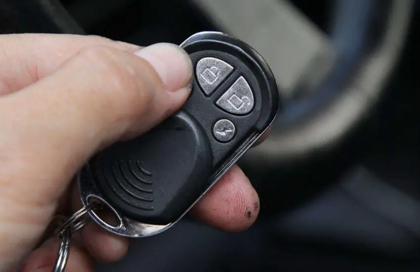
How to Disable a Car Alarm
Any driver might panic and think of one thing: how to disable the car alarm in such a frustrating situation?
There is no doubt that alarms are an important component of any car. Primarily, it is installed in vehicles to enhance the safety of the driver and the car itself.
It not only helps to deter any unauthorized attempts to access the car but also to repel theft attempts, if necessary.
But certain situations likely occur when you might need to turn it off while it’s causing loud noises or when the remote is malfunctioning, certainly. So knowing some tips from a pro can prove useful in such moments. And here’s how to do it!
How to Disable a Car Alarm in Less Than 2 Minutes?
The car alarm can malfunction almost anywhere. One thing everyone should know is that there is a security system equipped in every car and an alarm system to ensure security against theft.
It is quite comparable to the chip code of the key, which is generated by your vehicle when the ignition is turned on. This can even happen when you place the key in your vehicle’s door.
The car alarm can malfunction almost anywhere. (Photo: Wikihow)
Follow these steps to get through the situation like a pro!
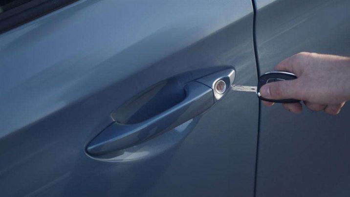
1. First Step – Try Opening the Door with the Key
This is the simplest option to disable the car alarm: simply place your key in the driver’s side door to unlock the vehicle. Provided you have the car keys with you, you can try unlocking the side door.
Since car alarms are designed to prevent thieves or people without car keys, the alarms turn off when a key is properly inserted to lock and unlock the car.
You can try inserting it on either side of the doors, but we recommend testing the driver’s side for more effectiveness. And if the door is already locked, car owners need to unlock it, then lock and unlock it again.
If your car is equipped with a key fob, it’s time to use it to lock and unlock the door. Car owners can apply the same technique that disables various factory car alarms.
To be more precise, drivers need to stand close enough to the car for it to recognize the key fob. After that, simply press the lock and unlock button to turn off the car alarms.
If the door locks don’t open, there could be two cases: The first case is that the key fob batteries might be dead. You just need to change the batteries and try again.
The other case is that there might be a special option to disable the alarm. You should find out if there is a “switch” button that needs to be activated.
Last but not least, remember to avoid the panic button. It is a button painted yellow or orange on the key fob. If drivers press it, their car turns on a flashlight and honks the horn.
When the panic situation is activated, you need to either press the button again or start the car and drive.
Drivers might panic and think about one thing regarding ways to disable a car alarm. (Photo: Philkotse)
And what if you had a push-button start? Well, in that case, you can find the hidden key inside. This helps, especially when the remote is malfunctioning. Look for a small button on the side of the key fob.
Push it with your fingernail to get the hidden key. Now, I can simply unlock the car to reset the alarm.
2. Second Step – Head to the Ignition and Turn It On
This is undoubtedly the most obvious step in the car alarm disconnection guide. The driver can put the key in the ignition to disable the car alarm.
The chip key code will be generated by the vehicle, as the car can recognize the key. And when that happens, your car alarm will turn off.
3. Third Step: Reach the Alarm Fuse
In order to perform this step, car owners need to locate the alarm fuse. It is usually found just below the steering wheel.
Some modern automobiles have more than one fuse box, so you need to use a manual to find the one with the fuse powering the car alarm. Or simply look up its location online as we did.
Once you manage to locate the correct fuse, it’s time to remove it. Be careful when removing the plastic trims from your interior as they are fragile and easy to break. For this reason, car owners need to use pliers to remove the fuse.
If it is the correct fuse, the alarm should trigger immediately. However, if you fail to identify the correct one, drivers must remove and replace the fuses one by one.
Eventually, you will be able to remove the correct fuse. After replacement, car owners can use the tweezers to slide the fuse out once the alarm is off.
The alarm fuse is usually found just below the steering wheel. (Photo: Autoily)
Normally, the alarm will remain disabled even after reinserting the fuse into the fuse box.
Nevertheless, if it reactivates immediately once drivers put the fuse back in place, the alarm has issues. You might need an auto repairer to fix this problem.
Another thing to remember is that some aftermarket car alarms don’t have a fuse in the fuse box, so make sure to check that beforehand.
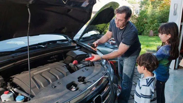
4. Detach the Vehicle’s Battery
Last but not least, removing the battery is also a solution to know how to disable the car alarm. To detach the battery, you need to be able to locate it. Unlike the fuse box, a car battery is easy to find.
Drivers only have to open the hood in the engine compartment and that’s it. If you can’t find it, it’s more likely to be in the trunk to improve weight distribution and save space.
How to disable a car alarm can involve disconnecting the battery. (Photo: Getty Images)
Once you manage to find the battery, it’s time to disconnect the ground wire located on the negative terminal. Drivers can find this terminal by looking for the minus symbol or the letters “NEG”.
Another way is to follow the thick black cable that connects to the car’s body. Car owners should hold a wrench to make the job easier.
By loosening the nut and sliding the cable off the terminal, you can completely turn off the alarm. But if the alarm is still activated, there might be backup batteries remaining.
In some aftermarket car alarms, small backup batteries support the alarm’s operation. So wait a moment and the computer will reset. Drivers should not force-reset the automobile’s computer as it could lose data.
The final step for car owners is to reconnect the battery after waiting for about an hour. Drivers can now reconnect the ground cable to the battery’s negative terminal.
Furthermore, drivers must ensure the cables are tightened properly and start the car to make sure there are no more issues.
Car owners can check this video from the Ternet blog if you need additional instructions on how to turn off the car alarm!
Car alarms are one of the most vital parts of any vehicle. But in case of malfunction, make sure to know these tips to solve the problem immediately, without embarrassing yourself in the middle of the road.
So, next time, don’t worry and don’t ask anyone how to disable the car alarm, just follow these tricks and avoid trouble.
How to Add Bluetooth to the Car
Bluetooth is now a standard feature on almost all modern vehicles, but with older models, that’s not always the case. If your car doesn’t have this feature, you might be missing out on a lot of driving enjoyment. So how to add Bluetooth to the car? In this article, we will share with you some simple ways to carry out this process:
Car Bluetooth: What is it and why do you need it for the car?
There are 3 ways to request adding a Bluetooth device for your car (Photo: pinterest.com)
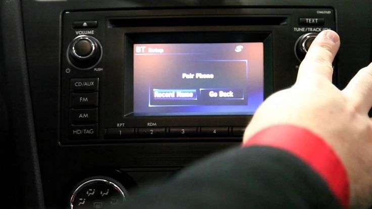
Simply put, Bluetooth is a wireless device built into your car and it will allow you to communicate with two compatible devices via radio waves. Most modern cars today equipped with an infotainment system will have Bluetooth connectivity. It’s a simple way to connect your car’s infotainment device to your smartphone. What are the benefits of adding Bluetooth to the car?
Hands-free connectivity: When connected to Bluetooth, your car’s screen resembles an enlarged smartphone screen. When a call comes in, simply press the button on the screen’s control panel. This will make your driving much safer.
Multifunctional entertainment screen: You will discover features for watching videos and listening to music directly on the large screen. Thanks to this, the entertainment experience will be much more enjoyable than watching on your phone’s screen or listening to boring songs on the radio.
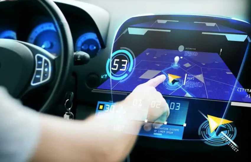
Vehicle maps and navigation systems: This benefit will greatly facilitate each of your trips. Looking at the map on a large screen will help you orient yourself more easily, thus helping the driver to drive with more peace of mind.
Voice control: The outstanding advantage of the Bluetooth connection between the phone and the car is the voice use function. Currently, Google Assistant allows users to control the car’s screen via voice, such as making calls, listening to music, displaying maps,…
How to add Bluetooth to the car: 3 different ways to do it
There are several ways to add Bluetooth to your car, so let’s find out how to connect Bluetooth to the car?
You can apply other useful methods, such as using a universal Bluetooth kit or a Bluetooth speaker (Photo: pinterest.com)
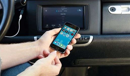
Using a Bluetooth receiver
We can say that the simplest and most common way to add Bluetooth to a vehicle’s radio is to use a pair of Bluetooth receivers. With this device, you can connect non-Bluetooth equipment to your smartphone or another Bluetooth-compatible device and allow you to stream from them, including speakers, docking stations, a hi-fi system, headphones, and a stereo system. You can do this by pairing your phone with the Bluetooth receiver. And any audio you stream from your phone will be sent to the receiver which then plugs into the 3.5-millimeter input jack (located in the center of the console or stereo system) or into your vehicle’s auxiliary input.
We can say that you will easily set up the Bluetooth receiver whenever you use a non-Bluetooth device. This receiver is small and portable, so it can be easy to put in your car or in your bag. You can fully control the sound of your device once connected.
Note that: You only need to pair the Bluetooth the first time you want to connect a new device to your car. After that, the audio device and your smartphone will connect automatically from the next time.
FM transmitter
If your car or radio doesn’t have an auxiliary input, you’d be better off using an FM transmitter. Generally, the FM transmitter is designed like a Bluetooth receiver, but instead of sending the audio to the stereo via an auxiliary cable, it will work with converters to transfer your audio output from the pre-existing source to audio signals. After that, the signal will be transformed into FM signals to help drivers adjust their radio frequency according to the transmitter. Transmitters usually connect to your headphone device and then broadcast the signal on the FM broadcast band, which will allow all nearby radio stations to pick up the signal.
Simply put, an FM transmitter also known as a miniature radio has the main responsibility of transforming the radio signal from devices (iPod, iPad, or laptop) into a wireless FM stereo signal and converting them. At that point, you will hear the music streamed from your phone. However, a big advantage of the FM transmitter is the lack of wires, but depending on which one you buy, you might also suffer from occasional audio loss or static.
Car Bluetooth adapter
The last method is to use a Bluetooth adapter. The Bluetooth adapter will be a favorite choice for those who like to have technical objects. It will be a perfect option if you want to equip this feature to your car radio and moreover, it is also easy for you to install in your car. Bluetooth technology is increasingly used to adapt to the wireless environment like in vehicles. Using adapters will be convenient for communicating with other devices in your car with the computer or phone over a short distance. A Bluetooth adapter (or Bluetooth dongle) is a small device that allows your car’s wireless technology to expand its potential.
You just need to plug the USB Bluetooth adapter into your computer’s USB port, and all the Bluetooth devices you want to communicate with the PC adapter can do so. You can mount the microphone on the dashboard or attach it to the sun visor when you answer a call, you will hear the sound from the car’s speaker. However, we advise against making phone calls while driving. To ensure your safety, let’s stop and answer the phone.
In a nutshell
In addition to the 3 methods above that we shared, you can apply other useful methods, such as using a universal Bluetooth kit or a Bluetooth speaker. Hopefully, the article will provide you with useful solutions when adding Bluetooth to your car and we can say that car Bluetooth is a cutting-edge feature that you can consider equipping so that the vehicle can experience fun while driving.