Knowing how to test the ignition coil with a multimeter is one of the most necessary maintenance tasks because the ignition coil is a vital part of the vehicle’s ignition system, providing electrical current to the spark plugs. When the car doesn’t start or stalls frequently, the ignition coil may be damaged and needs to be replaced. A few simple tests can determine if the ignition coil is working well and keep your car as fresh as possible.
Ignition Coil Basics
Ignition components play an immutable role in the engine’s ignition system. Learning and understanding the details of this part will help drivers recognize the early signs when it is faulty and replace it in time.
In more detail, the ignition system is one of the three crucial elements of an internal combustion engine, besides compression and the air-fuel mixture. And in this, the ignition coil is the part that plays a central role in the system.
What is a Car Ignition Coil?
An ignition coil or a coil is a part of the car’s ignition system responsible for generating high-voltage currents that help the spark plugs release sparks to ignite the air-fuel mixture in the engine’s combustion chamber. This combustion creates pressure that pushes the piston to move and transmits force to the crankshaft to generate work.
Ignition Coil Structure
Ignition coils on cars are composed of 3 main components, including:
- The iron core is located in the middle of the coil, firmly inserted into an insulating cardboard tube.
- The primary coil is wound around the iron core. The end of the wire is connected to the battery and the ignition integrated circuit.
- The secondary winding also wraps around the iron core 100 times more than the primary coil. The secondary terminal connects to the battery and the spark plug.
All are housed in a steel tube with an insulating porcelain bottom, and the cap also uses high-quality insulating materials.
There are mainly four types of ignition coils used in cars:
- Common to the entire ignition system
- Common twin type for 4-cylinder engines)
- Common triple for 6-cylinder engines
- Individual for each cylinder, double
Common twin and triple coils will generate sparks simultaneously in cylinders operating in the same phase.
The Operating Principle of the Ignition Coil
The coil is designed to act as a transformer, tasked with generating high voltage to create sparks.
When starting the engine, the engine ECU from the car’s brain box will signal the ignition timing. At that moment, the battery will let current pass through the integrated circuit and into the primary coil to form magnetic lines of force.
The IC then quickly interrupts the current to reduce the flow, creating an electromotive force in the direction that counteracts the decrease in flux. At this moment, the secondary coil also generates an electromotive force of about 30kV, which is transmitted to the spark plug to form a spark.
Since the number of turns of the secondary coil is a hundred times greater than that of the primary coil, the electromotive force generated by the secondary coil will be very large. Furthermore, the greater the current in the primary coil, the higher the voltage in the secondary ignition coil.
Signs of a Failing Ignition Coil in the System
The car’s coil (ignition coil) plays a key role in creating combustion in the engine’s combustion chamber. Thus, if the can fails, the spark plug will malfunction at the same time. This faulty action can reduce combustion efficiency, affecting the power, smoothness, operation, and overall performance of the car’s engine.
Here are some typical signs of a failing ignition coil that you should watch out for before moving on to the “how to test the ignition coil with a multimeter” part.
The Car Has Black Smoke and Emits a Strange Smell
Faulty spark plugs will lead to incorrect ignition timing, and weak spark plugs will result in incomplete fuel combustion. This amount of fuel will pass through the exhaust pipe to the outside. If the exhaust temperature is too high, this fuel can ignite, causing engine backfire. The telltale signs are that the exhaust pipe emits black smoke or fuel smells and may trigger a strange explosion.
More Fuel Consumption Than Usual
Vehicles using more fuel than usual can be due to many reasons, one of which may be due to a faulty spark plug. When the turbine is damaged, the fuel is not completely burned, so to ensure operating pressure, the engine must increase the amount of fuel injected into the combustion chamber.
Engine Vibration, Jerking, Irregular Speed
Engine misfire leading to vibrations, jerking, and weakness are the most observable signs when the car’s spark plug has a problem. When the generated voltage is not high enough, the engine misfires (also known as stalling). The loss of one or two engines will cause uneven, irregular engine speed, leading to the car jerking when on the gas, and there may be a feeling of “stopping” during acceleration.
The Car Stalls Suddenly
A damaged ignition coil can cause a moving vehicle to stall suddenly, as the ignition coil that doesn’t fire will prevent fuel combustion.
Hard Starting or No Start Engine
A faulty ignition coil can cause a misfire in some or all cylinders, resulting in little or no work. This problem makes the engine difficult to start or even impossible to idle.
>> Check Now: Do you think the car won’t start? Don’t get tired of it, try these solutions instead!
The Check Engine Light On
A lit Check Engine light is a sign indicating that the engine or related components have problems. If the ignition coil is damaged, the central system will receive the error and send a message via the Check Engine error light.
How to Test an Ignition Coil
A damaged ignition coil causes engine ignition failure, which affects the car’s performance. Therefore, vehicle users should check regularly to avoid unpredictable damage and to manage or prevent consequences in time.
Overall, there are 2 methods for testing the ignition coil. One is a multimeter coil resistance test, and another is a spark test. In particular, the spark test method is applied quite commonly due to its simple operation and high accuracy. On the other hand, the multimeter test method has also been approved and applied more widely thanks to the convenience of support tools.
Things to Keep in Mind Before and During Testing the Ignition Coil
Before rolling up your sleeves to do a project related to the engine or idling, you should always take notes on these safety advisories on how to test a small engine’s ignition coil with a multimeter. These are indispensable warnings that you must not forget at any time because they will not only keep your safety at its maximum but also ensure that each of your actions does not trigger or cause serious damage. The advisories are listed as follows.
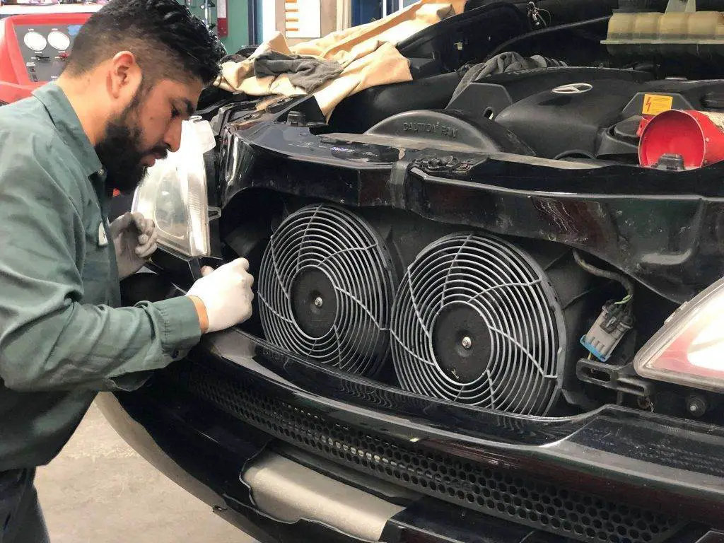
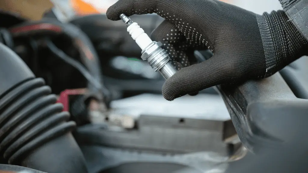
Wear Thick Rubber Gloves
With the ignition coil, even when testing or simply checking the component, do not forget to wear thick rubber gloves during full-time contact with the power source and exposure to power. These gloves will protect your hands from harmful chemicals in car engines and batteries.
The gloves will also protect your hands from exposure to rust around various engine parts. The last thing, and the most important, is that rubber gloves can protect you quite comprehensively from possible electric shocks. Because you will be working with spark plugs and batteries that can generate electrical energy, which can keep you absolutely safe without auxiliary and protective tools.
Furthermore, in any unexpected and unfortunate event where electrolyte accidentally comes into contact with your skin, body, or clothes, even in small amounts, you should always wash it off with a mixture of baking soda and water as quickly as possible.
Ensure the Car Engine is Completely Off
People tend not to turn off the engine when working with car parts to check their operation immediately. But the truth is that when you leave the engine running unattended, it is likely that you will receive an electric shock from the spark plug when trying to check your car’s ignition coils.
In principle, the coil will produce combustion gases and also transmit electricity during fuel combustion to make the vehicle run. So make sure the engine is off before starting any related work. Also choose a suitable workplace, for example in a well-ventilated environment.
How to Test an Ignition Coil with a Multimeter
Step 1: Remove the Ignition Coil from the Car
If you can use a multimeter that measures resistance, you can measure the efficiency of the ignition coil quantitatively and not in the somewhat subjective way described above. To begin this test, however, you need to remove the can so you can easily access its terminals.
Refer to the repair manual for precise instructions on removing the can.
Usually, you need to disconnect from the distributor wire, then remove the screw that secures it. Make sure your vehicle is off and cooled down before starting the process.
Step 2: Find the Standard Resistance of the Ignition Coil
Each vehicle’s ignition coil has its own coil resistance standard. If the actual resistance of the coils does not meet these standards, you know that your coil is damaged.
Generally, you should be able to find your can’s resistance standards by consulting the repair manual. Nevertheless, if you don’t find it, you can contact your dealer or via information on the internet. Most car coils will have a standard resistance of about 0.7 to 1.7 for the primary coil and 7,500 to 10,500 Ω for the secondary coil.
Step 3: Place the Ohmmeter Probes on the Primary Coil Terminals.
The ignition coil will have 3 electrodes + 2 poles on the sides and 1 pole in the middle.
Turn on your multimeter and touch the measuring tip of each multimeter to the 2 outer electrodes. Read and write down the resistance value – this is the resistance value of the primary winding.
Note that some of the newer coils have a different structure from this traditional arrangement. Refer to the vehicle manual for more information if you are unsure which connection electrodes correspond to the primary coil.
Step 4: Place the Ohmmeter Probes on the Secondary Coil Electrodes.
Next, hold the probe on one of the two electrodes and touch the other probe to the center contact (where the main high-tension wire connects to the distributor).
Read and write down the resistance value of the secondary coil.
Step 5: Determine if the Readings Match Your Vehicle’s Specifications.
Ignition coils are delicate components of a vehicle’s electrical system. If the resistance values of the primary and secondary coils are out of specifications, even by a small amount, you must replace the spark plug as it may be damaged.
How to Perform a Spark Test
Step 1: Turn Off the Machine and Open the Hood.
As with most types of maintenance, start with the vehicle parked and the engine off. Open the hood to locate the ignition coil. Although its exact location may vary from vehicle to vehicle, it is generally located near the fenders or bolted to a frame near the distributor.
Note that for vehicles without an igniter, the spark plug will be connected directly to the ignition coil.
A foolproof way to find the coil is to locate the distributor and trace the common high-tension wire that does not connect to any spark plug. Before starting, ensure you are wearing glasses or other eye protection and using insulated tools to prevent electric shock.
Step 2: Remove One of the High-Tension Wires from Its Spark Plug.
Next, remove the high-tension wire from one spark plug.
Usually, these wires run from the distributor cap to each spark plug. To avoid injury, use gloves and insulated tools when working with your vehicle’s electrical system.
If your car has been running for a while, its internal components can become very hot. As a rule, a vehicle that has been driven for about 15 minutes can warm the engine to about 200 degrees F. Park and let it cool for an hour to avoid injury.
To save time and avoid damaging your vehicle’s spark plugs, use a test spark plug instead.
- Instead of attaching the vehicle’s spark plug to the wire, attach the test spark plug to the wire.
- Ground for the ground clamp.
- Then, ask someone else to start the engine, looking for sparks across the test spark plug’s gap.

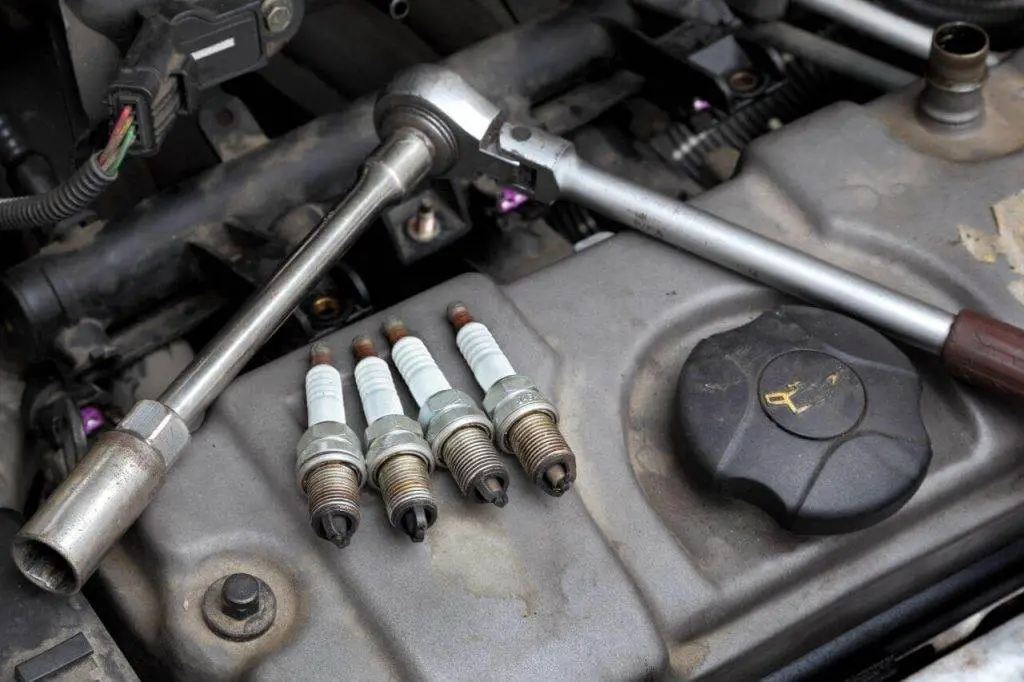
Step 3: Remove the Spark Plug with the Spark Opener Tube.
Once you have removed the high-tension wire from the spark plug, remove the spark plug. The easiest way is to use a specialized tool called a spark plug opener. From now on, be careful not to drop anything into the hole where you just removed the spark plug.
If small pieces enter the combustion chamber, it can cause major damage when the engine is running. At that point, it is very difficult to remove these pieces from the combustion chamber. So it’s best to take precautions to ensure this doesn’t happen.
Cover the hole with a clean cloth or towel to prevent small pieces from entering the combustion chamber.
Step 4: Reattach the Spark Plug to the Wire or High-Tension Wire.
Now, carefully reinsert the spark plug into the wire or high-tension wire. You should leave the spark plug connected to the distributor but not in the spark plug hole. Handle them with insulation to avoid electric shocks.
Step 5: Touch the Threaded Part of the Spark Plug with Any Metal Part of the Engine.
Next, skillfully position your spark plug (the wire is still attached) so that the “threaded” part of the spark plug touches a metal part of the engine. Again, make sure to grip the spark plug well with pliers or gloves. Do not risk electrocuting yourself by ignoring this simple safety measure.
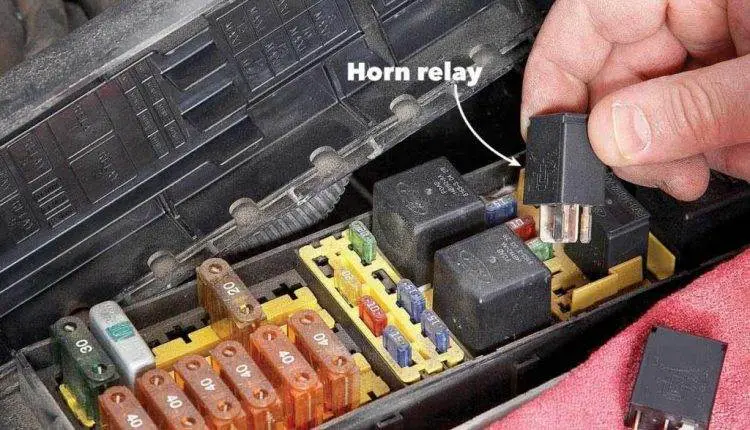
Step 6: Remove the Fuel Pump Relay or Fuse.
Before starting the engine to check the spark plugs, it is necessary to disable the fuel pump.
- Failure to remove the fuel pump relay means the tested cylinder is still flooded with fuel but there will be no combustion because there is no spark plug. This can also cause serious damage.
- Consult the manual to locate the fuel pump relay.
Step 7: Ask a Friend to Start the Engine.
Ask a friend to turn the car key to start the engine. This will power your car’s electrical system and the spark plug you are holding (assuming your ignition coil is working).
Step 8: Look for the Blue Spark.
If your ignition coil is working properly, when you start the engine, you should see a bright blue spark across the spark plug gap. This light will be visible in daylight.
If