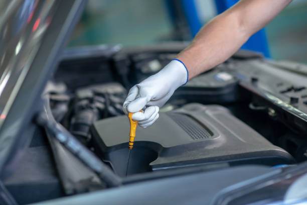
Car brakes are constantly being improved to enhance vehicle safety characteristics. They are one of the essential automotive systems in which manufacturers invest and develop. Drivers can be confident on every journey when brakes operate smoothly and effectively. Cars equipped with modern braking systems often have more competitive advantages in the market. Thus, this article will provide information on 5 types of car brakes commonly used in modern cars.
5 types of car brakes commonly used in today’s automobiles.
Brakes are mechanical devices that limit wheel movement by creating friction. As a result, car brakes in operation will help control speed or stop the vehicle at the driver’s discretion. In the early development of cars, brakes were merely logs attached to a wagon’s rims. The driver pushes the lever, and the wooden block will limit the wheel’s rotation speed. Later, to reduce heaviness, the wooden braking system was replaced with steel and leather.
However, they still did not provide the desired braking effect and caused annoying noises. The challenge for car manufacturers was the need to improve the braking system for safety, aesthetics, and to provide comfort for the driver. To date, modern cars are equipped with advanced braking systems to enhance usage safety.
For each type of car brake, there will be certain advantages and disadvantages. Therefore, to evaluate and compare which system is the best, we must base it on their pros and cons and compare them with our needs and control habits to choose the right type of brakes. Let’s explore the characteristics of these different brake types in detail in the next part of the article.
Drum Brakes
Drum brakes are commonly used on two or four-wheeled vehicles. Drum brakes on cars often use hydraulic brakes as they utilize hydraulic pressure to push the brake pads. When the driver presses the brake pedal, the pressure presses two brake shoes against the drum. This will create friction and cause your car to slow down and stop. Drum brakes include many components such as brake shoes, brake pads, linings, springs, brake drums, etc., which play different roles in the braking system.
- Brake Shoes: Made from die-cast aluminum, lightweight, and offering good heat dissipation. Brake shoes come in many different models and are made specifically for each model and year of manufacture. They are typically shaped like a circle with two semi-circular toes. This component is located in a part of the drum brake, but the brake shoe does not touch or come into direct contact with the drum.
- Wheel Cylinder: Functions as a chamber containing a piston and oil to transmit fluid pressure into mechanical movement.
- Return Spring: When the oil pressure decreases, the return spring forces the piston back to its original position.
- Piston: The part that is connected to the brake shoe. When there is oil pressure, this part will push, which forces the pads to press against the brake drum to help the vehicle stop.
Advantages:
- High durability, adapt to many different weather and terrain conditions thanks to the sealed design, avoiding environmental factors such as dirt.
- Save on maintenance, replacement, and installation costs.
- The brake drum has a simple structure, making it easy to disassemble. And, the cost is low.
- Ensure necessary safety; the car does not skid during braking.
Disadvantages:
- Compared to disc brakes, drum brakes have more weight and a slower deceleration time.
- The sealed design makes heat dissipation capacity poor, reducing braking performance, especially during urgent braking.
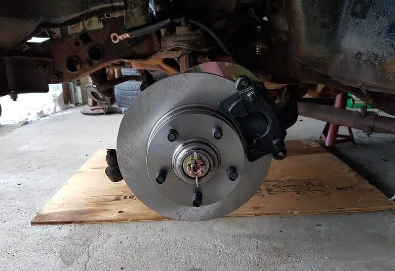
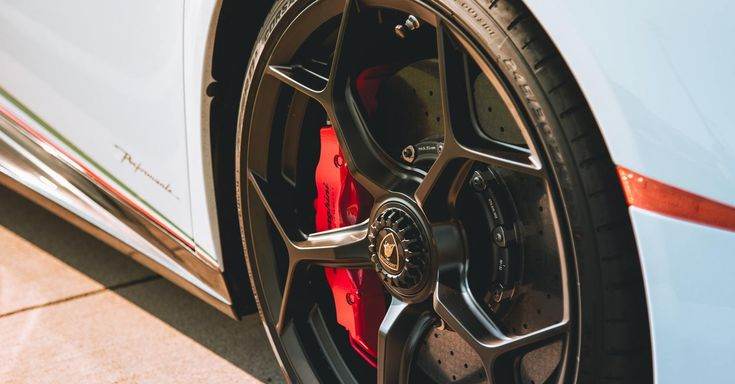
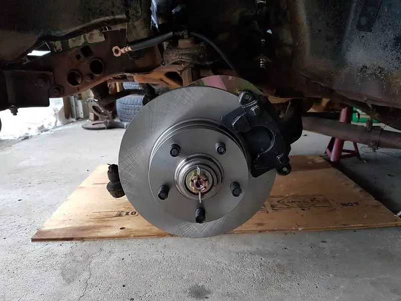
Disc Brakes
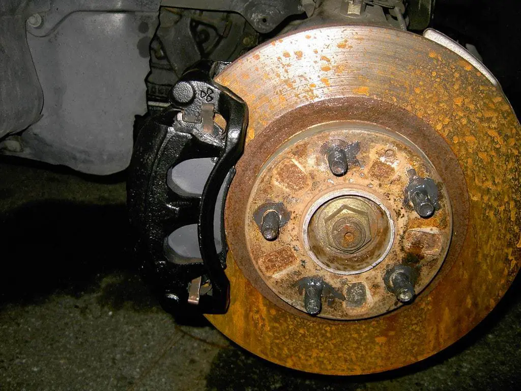
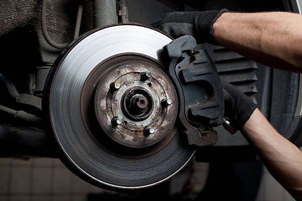
Possessing many exceptional advantages over drum brakes, disc brakes are equipped on the front wheels of many commercial vehicles. When drivers press the brake pedal, the oil pressure in the line and the wheel cylinder increases, pushing the piston and brake pads against the brake disc, creating friction and slowing the wheel.
So, what is its structure? A disc brake consists of 4 main parts: rotor, caliper, pad, and piston. This brake combination is designed to be open, and the components have flexible coordination, helping the car stop or reduce speed effectively.
- Rotor: Today, most rotors are made of carbon steel. It is a material with good heat resistance, good load-bearing capacity, and high durability.
- Caliper: Has the effect of holding and pressing the brake pads against the brake disc to generate sufficient braking force to help the vehicle decelerate and stop smoothly.
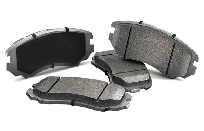
- Brake Pad: Brake pads are a unified block made from heat-resistant materials such as ceramic, metallic, and organic pads. This part of the car disc brake structure consists of 2 clamps that grip the brake disc.
- Piston: The working principle of disc brakes is to use specialized fluid to transmit force. When the piston is operating, it exerts pressure on the brake pads against the brake disc, helping the vehicle slow down or stop.
In addition to the 4 main parts above, disc brakes also have springs and air filters to help the disc brake system operate smoothly and efficiently. Besides using disc brakes on modern cars, most car manufacturers equip optimal braking assistance technology, such as anti-lock braking systems and brake force assistance systems.
Advantages:
- Deceleration efficiency is much higher than drum brakes due to greater friction force.
- The material is heat-resistant, has good bearing capacity, is durable, less prone to damage, and its weight is lighter than drum brakes.
- Disc brakes have an open structure to increase heat dissipation and water drainage. From there, performance is improved, and technicians can easily observe faults for cleaning and repair.
Disadvantages:
- Because the disc brake is designed to be exposed, it is easy for dust to stick, reducing efficiency after long-term use. Therefore, drivers must pay attention to cleaning them or taking them for regular maintenance to avoid damaging these parts.
- The friction between the pads and discs can cause noise while driving the vehicle.
- Disc brakes are made from high-quality materials to ensure vehicle safety. However, the maintenance and replacement cost of disc brakes is much higher than that of drum brakes.
Emergency Brakes
The emergency brake, also known as the parking brake, is mechanically operated and serves to keep the vehicle in place when parked. Even if the vehicle is parked on different slopes.
When there is poor friction between the tire and the road surface, the parking brake will prevent the wheels from moving. Depending on the driving factor and how it is controlled, the handbrake is divided into two types: mechanical and electronic. Each type has a different structure, working principle, and application.
Mechanical Handbrakes
They consist of a cable connected to the 2 rear wheels. When the driver pulls the brake, the cable acts on the rotating lever, converting the pulling force into pressing the brake shoes into the drum, limiting the wheel’s rotation to help your car stop. If the rear wheel uses a disc brake, the mechanical handbrake will use this mechanism to stop the vehicle.
Advantages:
- Low production cost due to simple design
- Easy to disassemble, repair in case of breakage
- Component lifespan is longer than that of electronic brakes.
Disadvantages:
- Occupies a large area of the car due to its bulky structure
- Many details and manipulations make it difficult for the driver to use
- Too high cost for periodic maintenance to avoid brake locking.
Electronic Handbrake
The electronic handbrake was invented later, possessing exceptional and more modern advantages, so it is commonly used. It has a structure consisting of a DC motor actuator mounted on the two rear wheels and an EPB (Electronic Parking Brake). The operation of the electronic handbrake is ensured by the electric motor. When you pull the brake, the electrical signal is transmitted to the electric motor of the rear wheels via the EPB to help the vehicle stop. Drivers must pay attention to pressing the brake pedal first, then pulling the control lever to activate the brake.
Advantages:
- The compact design saves a lot of space for the car.
- Simple operation with a modern structure.
- Avoid unnecessary accidents when the driver forgets to release the brake.
- Limiting the locking situation, brake locking occurs in mechanical brakes.
Disadvantages:
- When there is no more battery, the handbrake cannot function
- The brake pedal has a slight vibration when moving
- Component lifespan is lower
Anti-lock Brakes (ABS)
The ABS braking system is an active safety system common to most cars today. This system works to slow down, stop, and park the car when needed. When the car brakes suddenly on a slippery road, the phenomenon of wheel locking is likely to occur. This causes the wheel to skid on the road during braking, endangering drivers. Anti-lock brakes were developed to solve this problem. ABS helps reduce the risk of accidents through optimal braking control. The ABS braking system of a car is composed of parts: a speed sensor, a hydraulic valve, and a control system.
- Speed Sensor: The part that helps the ABS system detect whether the wheels are locked or not. These speed sensors are placed on each wheel or differential.
- Hydraulic Valve: A valve that controls the brake pads at each wheel. It will be located in 3 basic positions. Open valve (the force applied by the driver, the brake pressure will create the equivalent force directly transmitted to the wheel). Blocking valve (received brake pressure greater than the force applied by the driver). Release valve (received brake pressure less than the force applied by the driver).
- Control System: Receives the task of collecting information and data from speed sensors, then calculates and makes appropriate adjustments to the optimal brake pressure for each wheel.
Advantages:
- Cars equipped with an anti-lock system will operate particularly during braking on slippery roads or during emergency braking, ensuring the car’s stability during braking, giving the driver more time to handle the situation and protecting drivers.
- Optimize the space inside the cockpit, save space.
- Operations are also simpler and more convenient.
Disadvantages:
- Many people mistakenly believe that the main effect of ABS is to reduce braking distance. The reality is not like that.
- Higher production and repair costs due to modern technology and more complex features.
- Studies have also shown that ABS is not really effective on dry roads and has longer braking distances on snow.
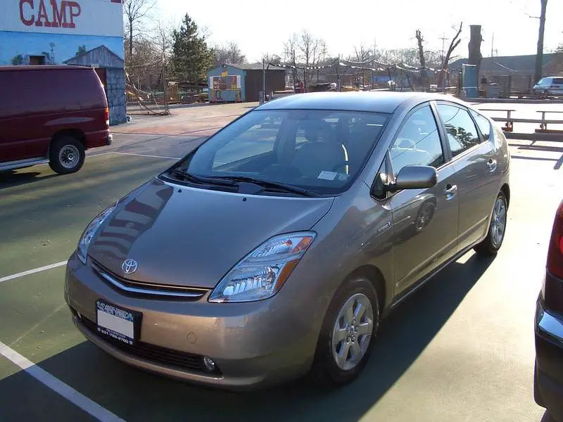
Regenerative Braking System (RBS)
Regenerative braking is one of the modern technologies in the automotive industry. It is used in electric and hybrid vehicles, as well as some gasoline vehicles. RBS converts kinetic energy into electrical energy for cars, thereby helping to increase energy efficiency. On traditional car models, a large amount of energy is wasted if conventional braking is used. Because if the driver presses the brake pedal while the vehicle is moving. The braking surface is repelled by the friction of the drum or brake pads and completely wastes heat.
When braking a hybrid or EV, the electric motor switches to generator mode. The wheels transmit kinetic energy through the transmission to the “generator.” The generator converts a large portion of the kinetic energy into electrical energy, which is then stored in the vehicle’s high-voltage battery. At the same time, the resistance of the generator generating electricity will slow down the vehicle.
Of course, this braking process takes a long time until the car stops. Thus, when more braking torque is needed than the generator can provide. Additionally, braking is performed by friction.
Advantages:
- Increase energy efficiency: reduction in fuel consumption and CO2 emissions, especially in urban traffic situations involving frequent braking and acceleration.
- Reduce wear: during regenerative braking, when the motor no longer receives energy from the battery, it restarts the wheel’s rotation, using mechanical energy and returning energy to the storage battery. Therefore, reducing wear and extending brake life is evident.
- Not much heat loss: traditional braking systems apply friction to convert mechanical energy into heat. Thus, from an energy perspective, braking generates an amount of heat that cannot be reused. However, regenerative braking slows the vehicle in a very different way.
- Energy conservation: The flywheel absorbs energy during braking through a clutch system that reduces the vehicle’s speed and increases wheel rotation. For acceleration, another clutch system connects the flywheel to the transmission, increasing the vehicle’s speed and reducing the flywheel. Thus, energy is conserved by heat and light, which often occurs in the braking system simultaneously.
Disadvantages:
- Only effective during deceleration at very low speeds. Because the braking torque generated by the generator is not sufficient to stop the vehicle in a short time.
- The regenerative braking system has its own advantages when the car is moving in the city. However, the vehicle’s fuel consumption is even higher when driving on the highway.
In conclusion
The above is a summary of types of car brakes and things to know about car brakes so that drivers can refer to them for brake system maintenance and complete their knowledge on vehicle usage. Please always update the latest information from Car From Japan for safe and enjoyable driving.