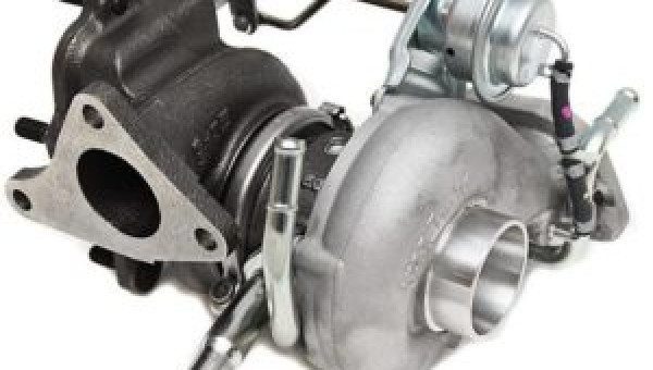
Are you having issues with slow turbo spool and significant turbo lag in your engine, or do you just want to understand what it means?
Are you having issues with slow turbo spool and significant turbo lag in your engine, or do you just want to understand what it means?
![]()
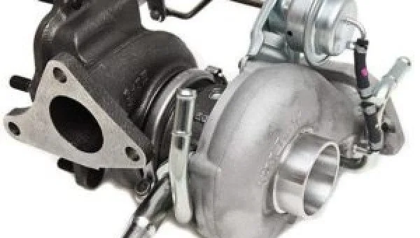
As soon as you notice problems with your car, the most frequently asked question is whether worn parts should be repaired or replaced.

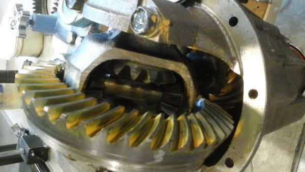
The rear differential is extremely important for the proper overall functioning of your vehicle.
![]()
Is your transmission having strange shifting problems and unexpected error messages on the dashboard?
![]()
The oil cooler is an essential component of every vehicle, whether it’s a sedan, SUV, or full-size truck.
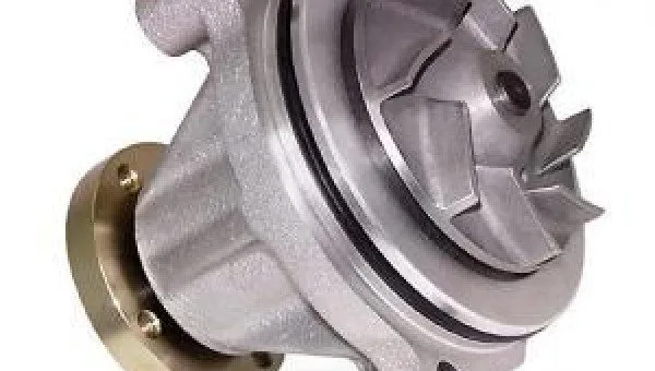

A vehicle’s engine runs at a specific temperature. This temperature must be maintained; otherwise, the engine may stall and refuse to start.
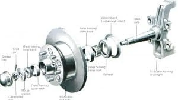
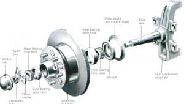
Bearings are components that are designed with high precision to ensure they support the proper functioning of mechanical movements.
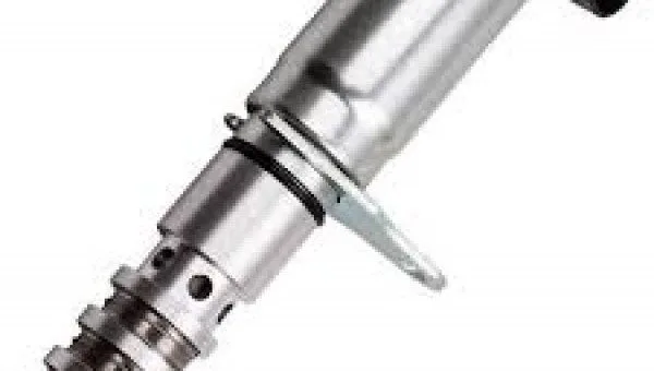
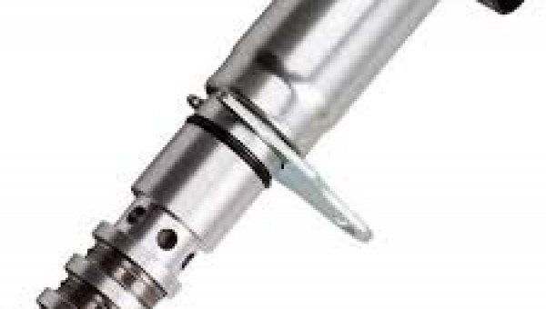
Variable Valve Timing (VVT) solenoids are one of the greatest innovations in the automotive industry.
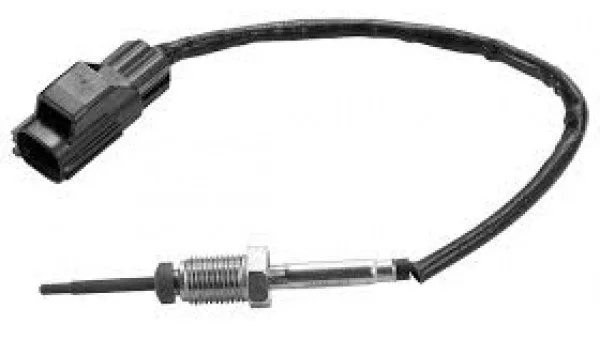
EGR Temperature Sensor – Symptoms, Function
This EGR valve is controlled by an EGR temperature sensor. The sensor collects vital information, and based on this data, the EGR valve determines when to open and close.
When the EGR temperature sensor fails, it causes various problems with the EGR system, and the situation must be addressed promptly. In this article, we will discuss some of the symptoms you may face due to a faulty EGR temperature sensor.
The first symptom you will notice is that the check engine light comes on. Any issue with the engine or sensor triggers the check engine light, indicating that the car needs to be diagnosed.
One of the initial problems you may notice is that the engine starts making a knocking noise. A faulty EGR temperature sensor will disrupt the EGR system flow, causing an increase in cylinder temperature. This temperature rise produces a strange sound that can be heard near the engine compartment.
If you hear such a noise, it means there is some kind of problem with the combustion process, and it should be fixed immediately. Delaying the issue for too long can lead to complete engine failure.
If your car’s EGR temperature sensor is faulty, it will fail the emission test. A defective sensor can give a false reading to the ECU, and as a result, the EGR system may crash. If your vehicle fails the emission test, you are breaking the law, so it’s a good idea to have your car diagnosed right away.
Modern vehicles are equipped with an exhaust gas recirculation system that is responsible for routing exhaust gas to the intake, reducing combustion temperature in the engine. The reduced combustion temperature helps minimize NOx emissions and prevents the engine from making a knocking noise.
However, the exhaust gas recirculation process is not always required. For example, when the engine is idling, the combustion temperature is already low, and there is no need for exhaust gas. To regulate this, the EGR valve is present, which opens and closes as needed.
We suggest entrusting your car to a professional mechanic if your car requires EGR temperature sensor replacement; however, if you have some experience in diagnosing automotive-related issues, you can also perform the replacement procedure at home.
• Protective gloves
• Protective glasses
• Ratchet/socket wrench
To locate the EGR temperature sensor, open your car’s hood. The EGR temperature sensor is located in the exhaust manifold or near the EGR valve.
To protect yourself from electric shocks, it is important to disconnect the car battery. Locate the negative terminal of the battery and disconnect it.
After removing the battery, unplug the electrical connector.
Once the electrical connector is removed, unscrew the EGR temperature sensor using a socket wrench or ratchet. Be sure to turn gently to avoid damaging any nearby components.
After removing the old sensor, mount the new sensor and screw it in firmly. Reconnect the electrical connector once the sensor is installed.
Once the electrical connector is connected, reconnect the battery negative terminal and start the engine. It is recommended to start the engine and drive for a while after the replacement procedure is completed.
A typical EGR temperature sensor should last a lifetime, but it sometimes gets damaged, mainly due to carbon buildup or intense and prolonged exposure to heat and carbon, but also if the car has experienced continuous temperature fluctuations. If the sensor becomes faulty, we recommend having the EGR system checked as well.
The average cost of replacing an EGR temperature sensor ranges between $190 and $260. Labor costs range from $30 to $80, while the part itself costs between $150 and $200.
The price generally depends on the car model and brand. Additionally, each auto repair shop has different prices, so it is recommended to do market research before choosing the best one. Official dealerships usually charge extra, while local mechanics are relatively cheaper.
If you want to save on costs, you can order the parts yourself from online retailers and only pay your mechanic for the labor cost.
Before replacing the EGR temperature sensor, it is wise to clean and maintain the sensor to see if the problem is resolved. Due to carbon buildup, the sensor sends incorrect information, causing the EGR system to malfunction.
The best way to clean the EGR temperature sensor is to use a clean, dry cloth. Avoid using harsh chemicals as they can damage the sensor. If the sensor is still not fixed after cleaning, we recommend replacing it with a new one.


The operating temperature of a car engine is between 90.5 and 104.4 degrees Celsius, as a lot of energy is dissipated as thermal energy due to the high combustion rate in the engine.