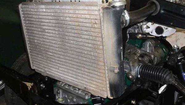
The radiator’s function is to prevent the vehicle’s engine from overheating.
When an engine is running, it generates a lot of heat. There is a liquid called “coolant” in the engine that engages the heat and absorbs it. The coolant now being hot, the fluid must cool down again by passing through the radiator. Once cooled, the coolant leaves the radiator and returns to the engine. The process will then start again.
### The 4 Main Symptoms of a Bad Radiator
The cooling system of virtually any vehicle depends heavily on the radiator to function properly. If the radiator remains functional, the engine will stay cool and not overheat. But if there is a problem with the radiator and it starts to malfunction or perform poorly, you will experience many easily recognizable symptoms. Below are the 4 main symptoms you can expect with a bad radiator.
1. **Engine Overheating** – The most obvious symptom of a bad radiator will be an overheated engine. Since its job is to keep the engine cool by circulating coolant, a bad radiator won’t do that. You will then start to see your engine temperature become very hot via the indicator on your dashboard. If the issue is not resolved immediately, the engine will eventually fail, meaning your vehicle will no longer be able to move. If you wait for your engine to fail, you are looking at an even higher replacement cost than just replacing the radiator.
2. **Coolant Leak** – The problem with your radiator could be that it has a leak. This means that the coolant passing through it will leak underneath and reach the vehicle’s floor. This can happen at any time, whether the vehicle is parked or moving. When you take your vehicle to the mechanic to have this checked, they will first perform a pressure test to ensure that it is indeed the radiator leaking coolant. If they determine it is the radiator, you will need to replace it.
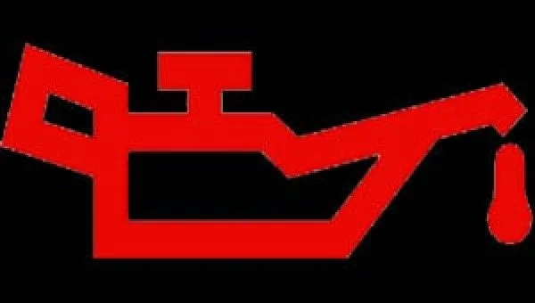
3. **Low Coolant Level Warning Light** – Following the previous symptom listed here, you should notice the low coolant level warning light illuminating on your dashboard. To keep your engine cool in the meantime, you can continue to add more coolant to it until you are ready to go to the mechanic and have the radiator replaced. Be sure not to add coolant for too long, as this will still put a lot of stress on the engine because there won’t be a sufficient amount of coolant due to the leak.
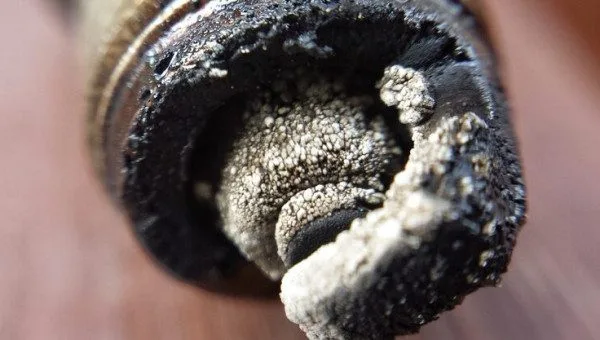
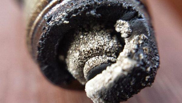
4. **Sludge Buildup** – The normal color of coolant is green or yellow. But when you have a bad radiator, the color of the coolant will change because it will be contaminated. Once the color changes due to contamination, there will be sludge building up in the radiator. This happens because the coolant remains in the radiator instead of being recycled into the engine. If you look at your radiator and see sludge, you must replace the radiator as soon as possible, otherwise your transmission or engine could be permanently damaged.