A compression test will reveal the condition of your engine parts and can save you money when purchasing a replacement engine.

A compression test will reveal the condition of your engine parts and can save you money when purchasing a replacement engine.
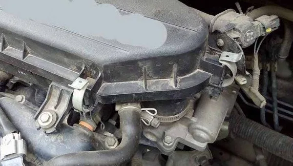
The intake manifold gasket is an essential component located between the cylinder head and the intake manifold. It provides the necessary seal to maintain pressure and prevent leaks of air, fuel, or coolant. Made of metal, rubber, paper, or composite materials, it ensures the proper functioning of the intake system, which is responsible for delivering the air-fuel mixture to the cylinders.
In Summary: A failing intake manifold gasket compromises engine performance, safety, and longevity. Act quickly at the first signs of symptoms!


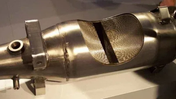

The internal combustion process in the engine causes the emission of many harmful gases. Fortunately,

A power brake booster, or hydraulic brake system, uses a hydraulic system while a vacuum brake booster uses a vacuum to stop your vehicle.

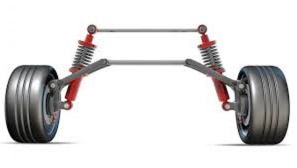
Shock absorbers and suspension struts are often referred to interchangeably because they perform the same function, however, they differ in the design of the suspension system.
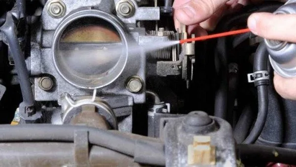
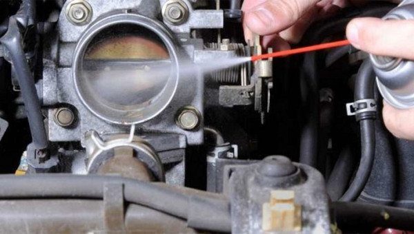
A vehicle’s throttle body is responsible for managing the amount of air flowing into the internal combustion engine.
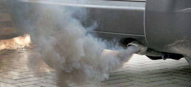

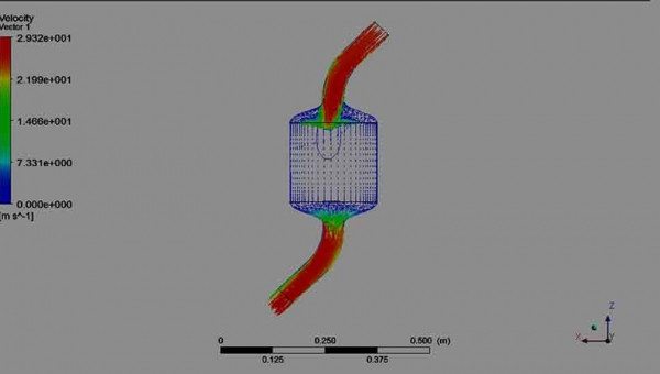
Diesel engines are known for creating a lot of smoke that sends toxic carbon emissions into the atmosphere.