Why Gasoline and Diesel Cars Don’t Use Lithium-Ion Batteries
Why don’t gasoline and diesel cars use lithium-ion batteries? The Lithium-Ion battery, called Li-ion, is rechargeable. It contains lithium ions. These move from the anode to the cathode during discharge. During charging, they move from the cathode to the anode. There are different types of lithium-ion batteries with different levels of cathodes made from other lithium molecules and carbon anodes. The chemical reaction between the anode, cathode, and electrolyte generates an electric current.
Lithium-ion batteries in cars: how do they work?
Lithium batteries, also called Li-on batteries, or Lithium-on batteries, abbreviated as LIB, belong to the rechargeable battery type. An assembly composed of many cells, like lead-acid batteries and many other battery types. The battery uses lithium metal or a lithium alloy as the negative electrode material and uses a non-adhesive electrolyte solution.
Lithium batteries can be divided into two types: lithium metal batteries and lithium-ion batteries (Li-Ion batteries). Lithium-ion batteries do not contain metallic lithium and are rechargeable. The reason this type of battery is commonly used in electric vehicles is that the battery itself and the materials it’s made from contain a higher power density than other battery types, allowing people to make a small-sized battery but obtain a much larger capacity.
Most electric motorcycles and cars currently on the market are equipped with lithium-ion battery technology because this type of battery has a long lifespan and better performance but is more expensive than lead-acid batteries.
A Lithium battery is composed of four main components:
Cathode: Determines the battery’s capacity and voltage and is the source of lithium ions.
Anode: Allows current to flow in the external circuit and when the battery is charged, lithium ions are stored in the anode.
Electrolyte: Acts as a conduit for lithium ions between the cathode and anode, formed from salts, solvents, and additives.
Separator: A physical barrier that separates the cathode and anode.
Why don’t gasoline and diesel cars use lithium-ion batteries? – What you need to know here
The different classes of Li-ion batteries have not yet reached the automotive sector. These remain present in popular consumer electronics, including laptops and smartphones. The problem arises when using them in diesel or gasoline cars for transportation. We recommend searching online for the best maintenance tips to keep your car running without any problems.
Needs Protection
Lithium-ion batteries are not robust. These require additional protection against overcharging and rapid discharge. The current must be maintained within safety limits. The major advantage of Li-ion batteries is that they require protection circuits to keep them within safe operating limits. You wouldn’t prefer to have a battery that constantly leaks due to overcharging or malfunctions due to undercharging.
Lithium-ion batteries: The Samurai Way (Photo Source: wikimedia)
Battery Cost
The disadvantage of using Li-ion batteries for your car is their cost. These cost 40% more than lead-acid batteries. When looking to install a reliable power source for your vehicle, you don’t consider choosing a battery where cost is a significant issue. The Li-ion battery requires integrated circuits to manage and ensure that the voltage and current are within safety limits, which increases its cost. The lead-acid battery offers car owners a reliable and less expensive option for their car.
Sensitive to High Temperatures
The car’s Li-Ion battery is very sensitive to excessive heat. Overheating the device or overcharging the battery usually leads to more heat. Heat causes battery cell degradation faster than usual. When driving in an arid climate, having a lead-acid battery would make more sense.
Safety Concerns
The risks of Li-ion battery explosion due to overcharging or overheating are always high. The decomposition of electrolytes leads to gas formation. This can ignite the electrolyte and cause a fire. Transporting the batteries poses a significant risk to you, especially if you are shipping them in larger quantities. You wouldn’t risk installing a car battery with a high risk of explosion in the vehicle.
The Lazy Way to Lithium-ion Batteries (Photo Source: wikimedia)
Summary
When deciding to replace the lead-acid battery with lithium-ion batteries that you are responsible for, make sure to read this blog to get a good idea.
What type of acid does a battery contain
A car battery is to the car what the brain is to the human body. It provides the vehicle with the energy needed to keep it running for as long as possible. In addition to supplying the car with the energy required for its proper functioning, the car battery also supports the headlights and some other built-in functions of the car. First, we need to understand what type of acid is in a car battery.
In this blog, we will discuss the chemical composition of a car battery and the chemicals used by different car batteries. You can also browse the internet for the best car maintenance tips to keep the battery operational.
What Type of Acid Does a Battery Contain? Read Below to Find Out
Manufacturing a car battery requires certain metal parts and chemicals. These elements affect the cost of batteries.
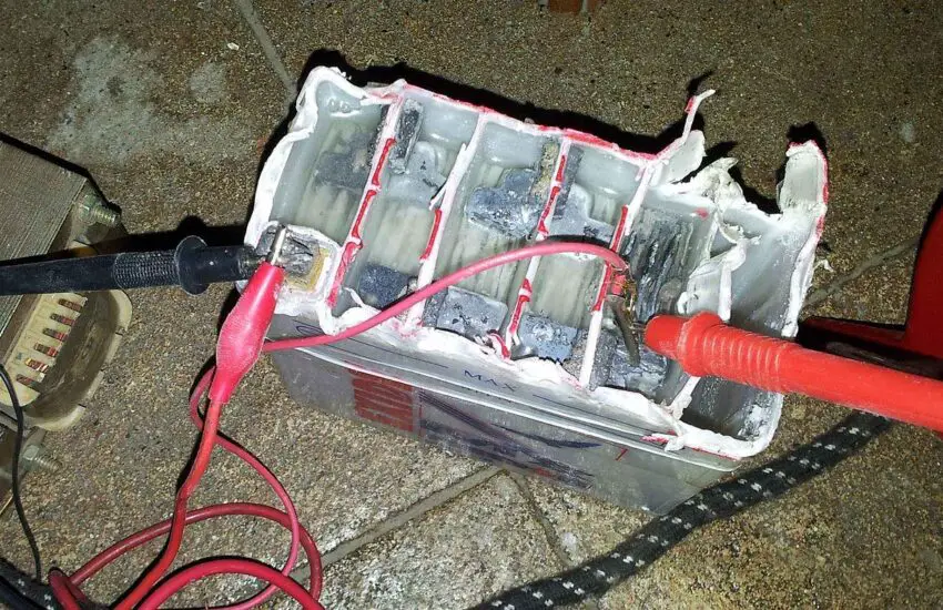
1. What is the Car Battery Case Made Of?
The basic idea behind sealing the car battery with a battery seal is to keep the battery body safe, which is the source of converting chemical energy into electrical energy. Now, to answer the question of what type of acid is in a battery, the battery case is made in different layers using various raw materials and may contain a layer of polyethylene terephthalate, a polymer layer, or layers of carbonized plastic.
Understanding what type of acid is in a battery (Photo source: thoughtco)
2. What Chemicals Does a Car Battery Contain?
The car battery contains at least 30 to 50% sulfuric acid in water, with 29%. The density of sulfuric acid is 1.25 kilograms per liter, and the pH is about 0.8. However, car battery chemical is a volatile and hazardous chemical, and proper protection should always be used when replacing it.
3. What is the Chemistry of a Car Battery?
The battery must have a different chemical basis that varies depending on the type of battery.
For example, a nickel-cadmium car battery contains nickel and cadmium for a longer lifespan, a wider temperature range, and a high discharge rate. A zinc-carbon car battery contains manganese dioxide as the cathode, zinc as the anode, and zinc chloride or ammonium chloride as the electrolyte.
Lead-acid batteries, on the other hand, contain lead dioxide and metallic lead as the anode and sulfuric acid (electrolyte). The lithium-ion battery uses different substances, but the best combination is carbon as the anode and lithium cobalt as the cathode.
Finally, the reusable alkaline battery features an anode, which is zinc powder, and a cathode made of a mixture of manganese dioxide. The battery gets its name from the potassium hydroxide electrolyte, a soluble substance.
Myths about the type of acid contained in a battery (Photo source: Pinterest)
In Summary
So, it depends on the type of car battery to know what type of acid is in a battery.
Do electric cars have radiators
Electric vehicles (EVs) have become a major force in the automotive landscape. These silent vehicles offer a cleaner and more efficient alternative to traditional gasoline cars. One of the main differences between these two technologies lies in their cooling systems.
Since electric cars lack internal combustion engines, a major source of heat in gasoline vehicles, the question arises: do electric cars have radiators?
So fasten your seatbelts and discover the secrets to keeping these electric wonders cool!
Traditional Cooling Systems and Radiators
Internal combustion engines, the workhorses of traditional gasoline cars, are like tireless athletes: they generate a huge amount of heat during operation.
This heat is a byproduct of the combustion process, where gasoline and air ignite in the engine’s cylinders, propelling the car forward.
However, excessive heat can harm engine performance and lifespan. Imagine running a marathon without ever cooling down: that’s what an engine would endure without a proper cooling system.
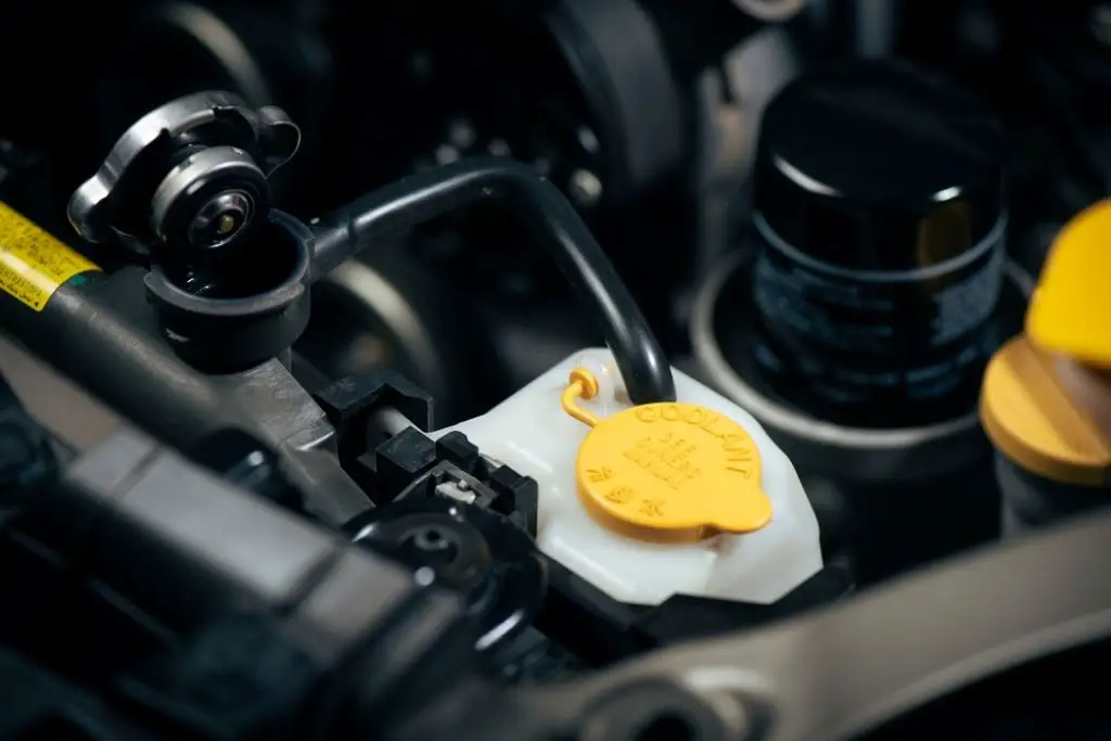
This is where the radiator comes into play: it acts as the hero of the story, ensuring the engine stays within its optimal temperature range. The radiator is essentially a heat exchanger, located at the front of the car.
It consists of a network of thin fins and metal tubes filled with coolant, a special liquid that absorbs heat. When the hot coolant circulates through the engine block, it absorbs heat from the engine.
The coolant then flows through the radiator tubes, where air flowing through the car’s front grille helps dissipate the heat into the environment. A fan mounted behind the radiator helps draw air through the system more effectively, especially when the car is idling or moving slowly.
Traditional cooling systems, while effective, have some limitations. They can complicate engine design and require regular maintenance, such as checking and replacing the coolant. Furthermore, leaks in the cooling system can lead to overheating, potentially causing serious engine damage.
Traditional cooling systems, while effective, have some limitations. (Photo: Nor Gal)
Do Electric Cars Have Radiators?
The fundamental difference between electric vehicles and gasoline vehicles lies in their power source. Gasoline engines rely on a process called internal combustion, where fuel and air ignite in the cylinders. This combustion process generates a huge amount of heat as a byproduct.
The engine must then expend extra energy to manage this heat, often requiring a complex cooling system with a radiator to prevent overheating.
Electric vehicles, on the other hand, operate on a completely different principle. They use electric motors powered by high-voltage batteries. Electric motors work by converting electrical energy into mechanical energy to spin the wheels.
While some heat is inevitably generated during this process, its amount is significantly lower than the intense heat produced by combustion engines. The reduced heat eliminates the need for a bulky radiator system like those found in traditional gasoline cars.
However, electric vehicles still require some form of thermal management to ensure optimal performance and battery health.
Although they don’t need the robust cooling systems of gasoline cars, electric vehicles often use alternative methods like liquid cooling or air cooling to maintain an adequate battery temperature.
Alternative Cooling Solutions for Electric Cars: Keeping Things Cool
Although electric vehicles (EVs) eliminate the need for a traditional radiator, thermal management remains crucial for optimal performance and battery health.
Unlike gasoline engines that generate enormous heat during combustion, electric motors operate at much lower temperatures. However, EVs still require effective cooling systems for several key components.
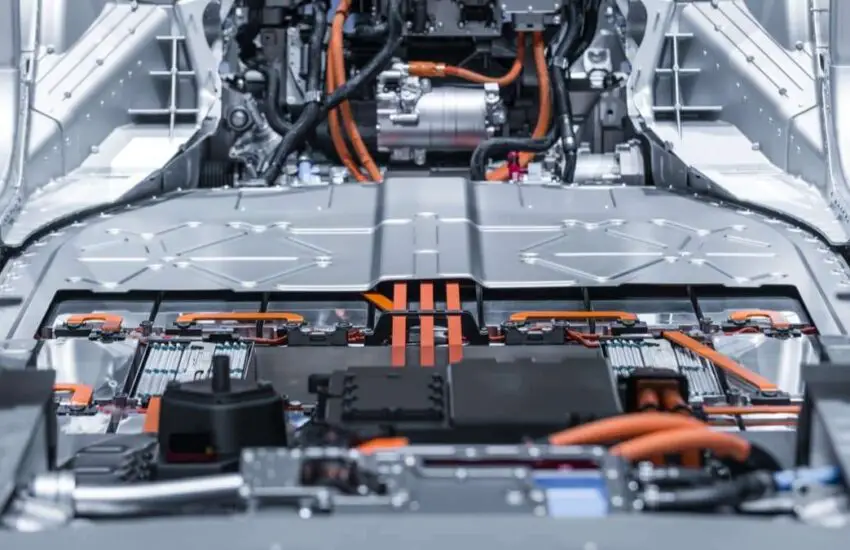
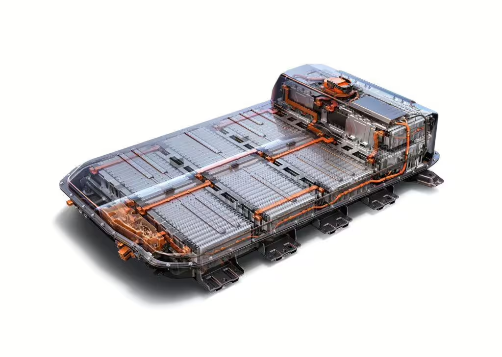
Battery Thermal Management
The battery is the heart of an electric car, and maintaining its optimal temperature range is essential. Two main methods are used to cool the battery.
Liquid Cooling: This is the most common and effective approach. A network of cooling channels runs through the battery.
A pump circulates a coolant that absorbs heat from the battery cells and transfers it to a radiator located at the front of the vehicle. Air flowing through the radiator then helps dissipate the heat.
Air Cooling: This method is typically used in smaller EVs or those with less powerful batteries. Strategically placed fans circulate air around the battery to cool the cells.
Although simpler and lighter, air cooling is less efficient than liquid cooling and may struggle to maintain optimal battery temperature in hot climates or during periods of high demand.
The battery is the heart of an electric car. (Photo: E-motec)
Additional Cooling Needs
Beyond the battery, other components in an electric car can also generate heat and require cooling.
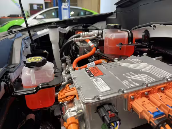
Power Electronics
The power electronics module, which converts electricity from the battery into a form usable by the electric motor, can also generate significant heat.
Often, these modules are cooled using a separate liquid cooling loop or strategically placed heat sinks that dissipate heat into the surrounding air.
Electric Motor
Although electric motors generate less heat than gasoline engines, they still require some level of cooling, especially under heavy load or high-speed driving. Some electric motors use a jacket filled with coolant that circulates around the motor casing to regulate temperature.
By implementing these alternative cooling solutions, electric car manufacturers ensure that all vital components operate within their optimal temperature range.
This not only optimizes performance and efficiency but also extends the battery’s lifespan, a crucial element of any electric vehicle.
Although electric motors generate less heat than gasoline engines, they still require some level of cooling. (Photo: CarsGuide)
FAQ
Do electric cars use the same type of radiators as traditional internal combustion engine (ICE) vehicles?
Electric cars do not use the same type of radiators as internal combustion engine vehicles. While they are equipped with cooling systems, these are typically designed to manage the heat generated by the battery, electric motor, and power electronics, rather than the engine cooling found in ICE vehicles.
How does the radiator system of an electric car differ from that of a gasoline or diesel car?
In an electric car, the radiator system is often more compact and focuses on cooling the battery, motor, and inverter.
These components generate heat during operation, but the overall thermal management requirements are different and often less intensive compared to the cooling needs of a combustion engine.
Can the cooling system of electric cars impact their performance and range?
The cooling system can significantly impact an electric car’s performance and range. Effective thermal management ensures the battery and motor operate within optimal temperature ranges, preventing overheating and preserving efficiency, which in turn can extend the vehicle’s range.
Do electric cars have multiple cooling circuits or a single one?
Many electric cars have multiple cooling circuits to handle the different thermal management needs of various components.
For example, there may be separate circuits for the battery, electric motor, and power electronics, each optimized for its specific cooling requirements.
What role does a heat pump play in an electric car’s cooling system?
Some electric cars use heat pumps as part of their thermal management system. A heat pump can move heat from the battery and other components to the cabin for heating, thereby improving overall energy efficiency, especially in colder climates.
How does ambient temperature affect the cooling needs of an electric car?
Ambient temperature plays a significant role in an electric car’s cooling needs.
In hotter climates, the cooling system must work harder to maintain optimal temperatures for the battery and motor, while in colder climates, the system may need to balance cooling and heating to ensure components remain within their operating temperature range.
Are there maintenance differences between electric car and traditional car cooling systems?
Maintenance of the electric car cooling system is generally less frequent and simpler than that of traditional cars, as there are fewer moving parts and no oil changes are required.
However, it is still important to regularly check coolant levels and ensure the thermal management system is functioning correctly.
Do electric cars use air or liquid cooling for their components?
Electric cars can use either air cooling or liquid cooling, but liquid cooling is more common in modern EVs due to its greater efficiency in managing heat for high-performance batteries and motors.
Final Words
Electric car technology continues to evolve, and we can expect further advancements in thermal management. Research into new cooling materials and more efficient air cooling systems promises even better performance and range for future electric vehicles.
So the answer to the question “do electric cars have radiators” is clear: electric cars do not need traditional radiators. Instead, they rely on a new generation of cooling solutions, paving the way for a cleaner and cooler future for transportation.
How do plug-in hybrid electric cars work?
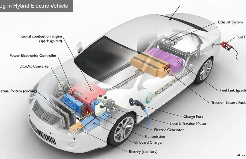
Plug-in hybrid electric vehicles (PHEVs) use batteries to power an electric motor and another fuel, such as gasoline, to power an internal combustion engine (ICE). PHEV batteries can be charged using a wall outlet or charging equipment, by the internal combustion engine, or through regenerative braking. The vehicle typically runs on electricity until the battery is nearly depleted, and then the car automatically switches to the ICE.
Key Components of a Plug-in Hybrid Electric Car
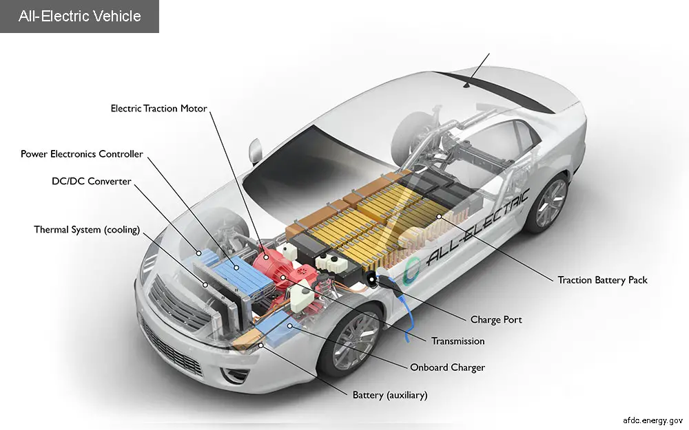
Battery (auxiliary): In an electric drive vehicle, the low-voltage auxiliary battery provides the electricity needed to start the car before the traction battery is engaged; it also powers the vehicle’s accessories.
Charge port: The charge port allows the vehicle to connect to an external power supply to charge the traction battery.
DC/DC converter: This device converts the high-voltage DC power from the traction battery into the low-voltage DC power needed to run the vehicle’s accessories and recharge the auxiliary battery.
Electric generator: Generates electricity from the rotating wheels during braking, transferring this energy to the traction battery. Some vehicles use motor-generators that perform both propulsion and regeneration functions.
Electric traction motor: Using energy from the traction battery, this motor drives the vehicle’s wheels. Some vehicles use motor-generators that perform both propulsion and regeneration functions.
Exhaust system: The exhaust system channels exhaust gases from the engine out through the tailpipe. A three-way catalyst is designed to reduce engine emissions within the exhaust system.
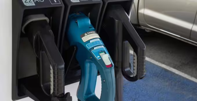
Fuel filler: A nozzle from a fuel dispenser attaches to the vehicle’s receptacle to fill the tank.
Fuel tank (gasoline): This tank stores gasoline on board the vehicle until it is needed by the engine.
Internal combustion engine (spark-ignited): In this configuration, fuel is injected either into the intake manifold or the combustion chamber, where it is combined with air, and the air/fuel mixture is ignited by the spark from a spark plug.
Onboard charger: It takes the incoming alternating current supplied via the charge port and converts it to direct current to charge the traction battery. It also communicates with the charging equipment and monitors battery characteristics such as voltage, current, temperature, and state of charge while charging the pack.
Power electronics controller: This unit manages the flow of electrical energy delivered by the traction battery, controlling the speed of the electric traction motor and the torque it produces.
Thermal system (cooling): This system maintains a proper operating temperature range for the engine, electric motor, power electronics, and other components.
Traction battery: Stores electricity for use by the electric traction motor.
Transmission: The transmission transfers mechanical power from the engine and/or the electric traction motor to drive the wheels.
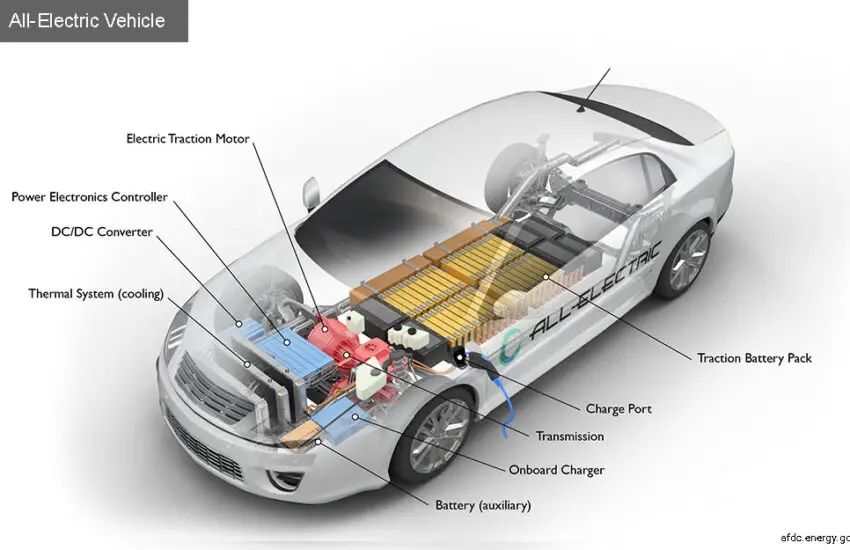
How do fully electric cars work?
Fully electric vehicles, also known as battery electric vehicles (BEVs), are equipped with an electric motor instead of an internal combustion engine. The vehicle uses a large traction battery to power the electric motor and must be plugged into a wall outlet or charging equipment, also called electric vehicle supply equipment (EVSE). Since it runs on electricity, the vehicle emits no exhaust gases and does not contain typical liquid fuel components, such as a fuel pump, fuel line, or fuel tank. Learn more about electric vehicles.
Key Components of a Fully Electric Car
Battery (All-Electric Auxiliary): In an electric drive vehicle, the auxiliary battery provides electricity to power the vehicle’s accessories.
Charge Port: The charge port allows the vehicle to connect to an external power supply to charge the traction battery.
DC/DC Converter: This device converts the high-voltage DC power from the traction battery into the low-voltage DC power needed to run the vehicle’s accessories and recharge the auxiliary battery.
Electric Traction Motor: Using power from the traction battery, this motor drives the vehicle’s wheels. Some vehicles use motor-generators that perform both propulsion and regeneration functions.
Onboard Charger: It takes the incoming alternating current supplied via the charge port and converts it to direct current to charge the traction battery. It also communicates with the charging equipment and monitors battery characteristics such as voltage, current, temperature, and state of charge while charging the pack.
Power Electronics Controller: This unit manages the flow of electrical energy delivered by the traction battery, controlling the speed of the electric traction motor and the torque it produces.
Thermal System (Cooling): This system maintains a proper operating temperature range for the engine, electric motor, power electronics, and other components.
Traction Battery: Stores electricity for use by the electric traction motor.
Transmission (Electric): The transmission transfers mechanical power from the electric traction motor to drive the wheels.
Converting a car to an electric car: the best used cars to buy now
Electric cars are making a lot of noise in the automotive industry. The trend is now towards green cars. While the demand for electric vehicles is rising, the supply of new and used electric vehicles is limited. A popular option is to convert a car into an electric vehicle.
Many engineers and car enthusiasts have successfully converted a used gasoline car into an electric car. You can be assured that there are many conversion kits and parts on the market designed for many specific car models.
Discover here the steps to follow to convert a car into an electric car with a list of the best used car models for different needs.
Can you convert a car into an electric car? – The Criteria
While a gasoline vehicle or a diesel car uses an internal combustion engine to produce energy, an electric car draws its power from batteries. The other components of these cars are basically the same, so in general, any vehicle can be converted into an electric vehicle.
Any car can be converted into an electric car. (Photo source: ecostandard)
However, some cars make such a conversion easier and more optimal. What are the criteria that make a car a better option for conversion?
Light Weight
The lighter the vehicle, the less energy the battery uses to move it. A lightweight converted car means better energy efficiency. This also allows the battery of the converted EV to have a longer “range,” meaning the battery will need to be recharged less frequently, which ensures a longer battery life.
Space for Batteries
The most important component of an electric car is its battery. Therefore, an ideal car for conversion must have plenty of space. Batteries must be well protected from heat, as it negatively affects the chemical reactions that occur inside the batteries.
Thus, batteries will typically be located inside the loading compartment or under the seats to keep them well covered.
The battery occupies the largest part of the space in an electric car. (Photo source: electricartrade)
A Solid Structure
Batteries are not only bulky but also heavy. A converted electric car will weigh a few hundred kilos more than with the gasoline engine, transmission, and a full tank.
With this extra weight, the car used for conversion must have a robust chassis design and adequate spring capacity to support this load and withstand the vibrations and forces caused by the car’s movement.
A chassis is the basic structure of a car. It can consist solely of the frame or also include the wheels and transmission, and sometimes even the car’s seats.
A Car in Good Condition
When you buy a used car, it is best to have it thoroughly inspected by a technician. Even though you won’t have to worry about the engine, the used car intended for conversion must have essential components in good condition, including brakes, steering, and suspension.
Manual Transmission
Cars equipped with a manual transmission are often chosen for conversion, as they allow the gear and axles to be kept in place.
Unlike a gasoline engine, an electric motor delivers 100% of its power instantly and continuously, so it will not need the multiple gears found in conventional vehicles.
How much does it cost to convert a car to an electric car?
According to automotive experts, the cost of converting a car to electric can range between $8,000 and $12,000, not including the cost of the “donor” car. The battery alone for an electric vehicle typically costs thousands of dollars.
The battery is the most expensive part needed for conversion. (Photo source: autocar)
In exchange for this initial cost, you can expect to save more money by using an electric vehicle. Since an electric vehicle has fewer moving parts than a gasoline vehicle, an electric vehicle is not prone to wear and tear and routine breakdowns, does not need regular oil changes, seal replacements, and many other regular maintenance tasks.
The Best Compact and Economical Cars
Meeting all the above criteria, the most popular choices for converting a car to an electric car are these subcompact cars:
Chevrolet Aveo
Geo Metro
Honda Civic
The Honda Civic is one of the most affordable and popular choices. (Photo source: driving)
The Best Pickups
If you need more space and compact cars are not your cup of tea, you can choose from these small two-wheel drive pickups:
Chevrolet S10
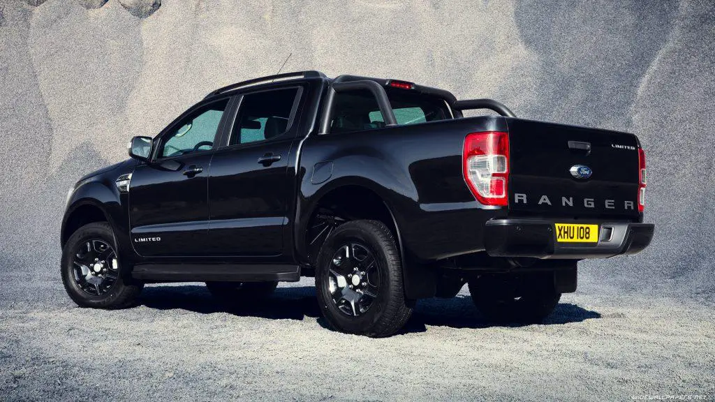
Ford Ranger
Toyota Truck
Nissan Body
The Ford Ranger is an affordable pickup to convert. (Photo source: topspeed)
The Best Low-Budget Cars
Green cars are the future of the automobile. However, embracing the future does not mean you have to forget the past. How about owning a classic model but with an internal “green engine”?
If you have a larger budget, you can opt for these classics to transform them into beautiful electric vehicles:
Porsche 911
Porsche 924
Porsche 929
Volkswagen Beetles
Volkswagen Golf
Ford’s Mustang
Triumph Spitfire
Triumph GT6
Mazda Miata
Toyota MR2
Fiat 124 Spider
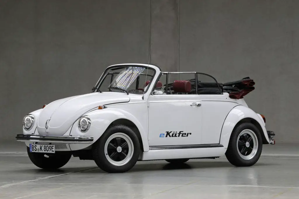
Volkswagen’s e-Beetle electric model. (Photo source: autoexpress)
The Volkswagen Beetle is indeed very popular for conversion to an electric car. The electric conversion of the classic Beetle is offered by so many aftermarket companies that Volkswagen eventually decided to get in on the action. The VW e-Beetle has 81 hp and a top speed of 93 mph.
The range is estimated at 200 km, meaning the electric Beetle needs to be recharged every 200 km. It also features DC fast charging, allowing a charge of about 75% in just one hour.
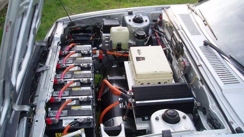
How to Convert a Car to an Electric Car
Once you have done all the research and determined the model to convert, the steps to convert a car to an electric car are quite simple.
Remove the components of the old internal combustion engine. These include the engine, fuel tank, muffler, exhaust, starter, and radiator.
Prepare the mounts for the electric motor and replace the old engine with the motor. The size of the motor will depend on the available space in the car and your preference in terms of power.
The electric motor is powered by a battery. Prepare the mounts for the battery and place the battery in the car. Lithium batteries are the best choice. The number of batteries used also depends on the available space.
Install the power controller in the car. The power controller is needed to regulate the power flow between the battery and the motor.
Add other necessary hardware, including a charging system to charge the batteries and a number of other hardware to operate the car’s air conditioning, heating, and steering systems.
Add wiring to connect everything together.
Charge the batteries and your converted electric car is ready.
Before driving your new vehicle on the road, make sure you have registered it according to your state’s laws.
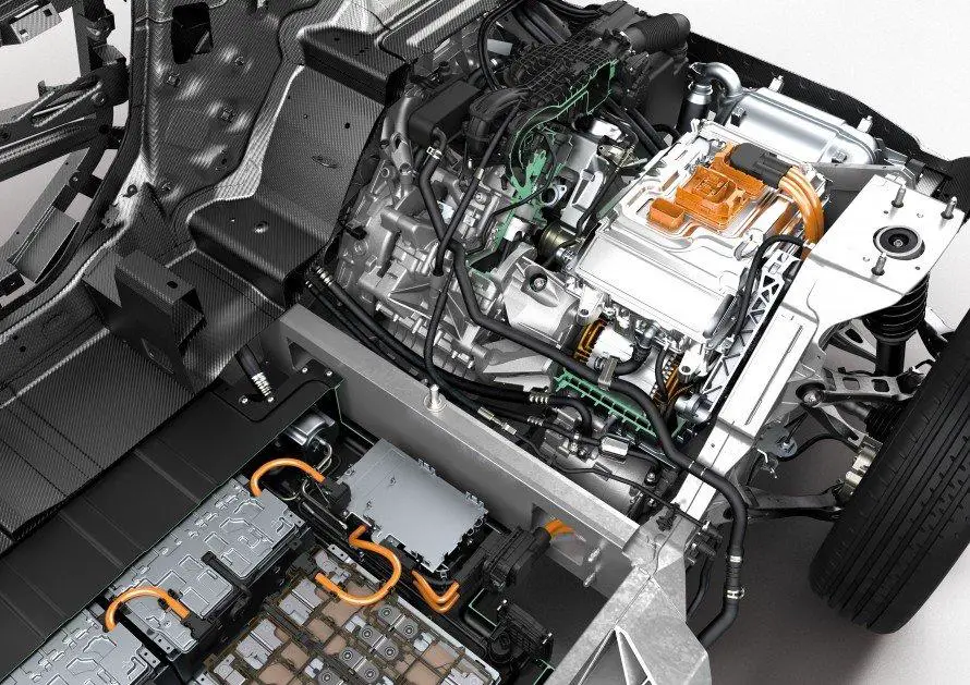
You will need many accessories in addition to the battery and motor. (Photo source: bmw)
Instead of buying a new car, convert it to an electric car to have more possibilities of owning a customized vehicle well suited to your needs and preferences. Now that you know how to convert a car to an electric car, make sure your converted electric vehicle lasts for many miles with our practical maintenance tips.
Mazda MX-5 NA/NB: RWD transmission, popularity in DIY projects.
Conversion Kits: Brands and Costs
Supplier
Price
Specifics
Electric Classic Cars
€15,000–25,000
Custom kits for classic cars.
EV Europe
€10,000–18,000
Brushless motors, Tesla-compatible controllers.
Transition-One
€8,500–12,000
Certified conversions for Twingo, Saxo, etc.
OpenInverter
€3,000–7,000
Open-source solutions (used Tesla Model S motors).
Recommended Motors:
Axial motor (e.g., Hyper9): 50–100 kW, easy to install.
AC synchronous motor (e.g., Tesla Small Drive Unit): 200–300 km range.
Critical Technical Steps
Removal of the thermal powertrain: Keep the gearbox (unnecessary in full electric conversion).
Installation of the electric motor:
Front-wheel drive: Motor in transverse position.
Rear-wheel drive: Motor mounted on axle (e.g., BMW E30).
Battery Integration:
Location: Under the floor (flat batteries) or in the trunk (Tesla modules).
Safety: Waterproof casing, liquid cooling system (e.g., BMW i3 modules).
Electronic Management:
BMS (Battery Management System): Mandatory for balancing cells.
Controller: Adjust power via open-source software (e.g., VESC).
Legislation and Homologation (France/EU)
Technical Inspection: Mandatory after conversion (Article R321-16 of the Highway Code).
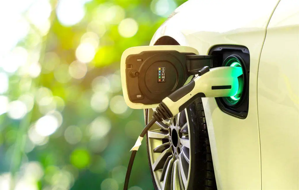
What are the different types of electric car chargers?
With the depreciation of fossil fuels, new methods of converting energy into means of locomotion are booming. Whether it’s hydrogen fuel cells or electric batteries, the share of modern cars using alternative means to propel themselves is on the rise. Electric cars and vehicles, in particular, are seeing the infrastructure to support them develop. Electric vehicle charging stations are becoming increasingly common, and the era of worrying about finding a place to charge an electric car is over. In 2021, the cost of charging an electric car became a more pressing concern than where to find an electric car charger in the first place.
Different types of chargers
There are several ways to break down the types of EV charging: by the equipment used, the charging speed of the device, the type of current used, and whether the device is public or private.
Electric car charging equipment
Electric vehicle power devices come in different forms, but the automotive industry has generally defined charging equipment as follows:
Socket – This is the interface of the charging device for inserting the cable.
Plug – This is the car charger plug that connects the cable to the device’s socket.
Cable – The cable that transfers electric currents from the device to the vehicle.
Connector – The part that connects the cable to the vehicle’s inlet and thus to the vehicle.
Vehicle inlet – The electric car charging socket that accepts the cable’s connector.
For a vehicle to be charged, it must be equipped with an inlet compatible with the sockets of the devices in the area where it operates. Therefore, efforts have been made to standardize sockets worldwide. Currently, there are three main types of car charger plugs:
Type 2 Connectors – Type 2 (also known as EU type, Mennekes, or IEC 62196) is the standard plug in Central and Western Europe, parts of South America, the Arabian Peninsula, South Africa, Australia, and New Zealand.
SAE J3068 AC6 Connectors – They are mechanically identical to Type 2 connectors. The differences mainly lie in the types of currents and voltages for which the devices are designed. This type has been adopted throughout North and Central America, including the Caribbean, as well as in South Korea.
GB/T 20234.2 Connectors – These connectors are incompatible with the other two types. Unlike the other two, GB/T uses a female vehicle inlet and a male connector. This variant is used exclusively in China.
Charging rate
This measure is important when choosing where to power your electric car, as it determines the time needed to charge the electric vehicle. The charging rate primarily depends on the device supplying electricity to the vehicle, but at higher rates, the car’s ability to accept current becomes the bottleneck. Overall, you can classify these devices into four general categories:
Electrical grid – Electric cars are usually equipped with a plug that can be connected to the electrical grid to charge the vehicle from there. The charging power is about 2 kW and can take more than a day to fully charge most vehicles from a depleted battery. Electric vehicle manufacturers recommend using it only in emergencies.
Slow chargers – If you’ve ever wondered how to charge your electric car at home, slow chargers with a power of 3 kW are increasingly common in households with an electric vehicle. This allows plugging in an electric vehicle overnight when it’s not in use. The long time required to fill the vehicle’s battery capacity is thus not an issue.
Fast chargers – Publicly accessible stations are usually of the fast charger type, with speeds starting from 7 kW. Fast chargers significantly reduce charging time compared to slow variants, making them more suitable for charging vehicles on the road.
Rapid chargers – The latest technology in this field, they can exceed the charging capacity of modern electric vehicle models. The power typically ranges from 120 to 350 kW. Rapid chargers are unknown in private homes and are usually found only in specific locations.
Current
There are two types of current: alternating current (AC) and direct current (DC). Most vehicles use direct current, but some models (like the Renault Zoe) use alternating current to charge the electric vehicle. Typically, an electric car requires DC power, as batteries store it that way, then release it to a transformer that converts it to alternating current for the motor to use.
Other factors to consider
There is another variable to consider when purchasing EV charging equipment: the cable length. While it’s true that longer cables suffer from power loss due to increasing resistance, electric car power cables do not reach lengths where this would be a problem. With lengths between 4 and 10 meters, the size of the cable to use for an electric car charger in the UK is determined by utility and price factors. Shorter cables significantly reduce the distance the electric car can be parked from a charging station. On the other hand, longer cables cost more, weigh more, and take up more space. If you can afford it, you should generally opt for longer cables. Naturally, the type of cable you buy must match the electric car charging sockets you are likely to encounter.
What to do when the car starter clicks constantly
It’s completely normal to feel frustrated when the car won’t start and the starter keeps clicking. Almost every driver faces this situation from time to time. Instead of wondering why the car starting won’t stop, find a way to get out of it. If you want to know exactly what you should do in this situation and what can cause the incessant clicking in the car, you’re in the right place.
So let’s explore together how you can handle the situation when a starter clicks uncontrollably.
The Importance of the Car Starter
Since the internal combustion engine cannot run on its own, it always needs external assistance. That’s why the vehicle’s starting system was developed and plays an important role in helping the vehicle start and operate.
The starter plays a crucial role in starting the vehicle’s internal combustion engine. This system works on the principle of converting the chemical energy stored in the battery into electricity, and then into mechanical energy in the engine.
To start an internal combustion engine, the crankshaft must be rotated at a certain speed (in gasoline engines, 50 to 100 rpm) for a few turns until the engine runs at full power. It can be said that the starting system plays an extremely important role in getting the vehicle moving.
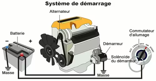
A car’s starting system consists of 6 components: the car battery, the ignition switch, the starter relay, the starter safety switch, the starter motor, and the battery cable. Each of these components performs a different task, and when they work together, they create a complete system.
The main function of a car’s starting system is to help the internal combustion engine operate.
During driving, to prevent voltage drops and the need for large-diameter cables, the starting system circuit is divided into two sub-circuits: the starter control circuit and the high-current electric starter circuit. Each type of circuit is structured and operates according to different principles.
Your Car Starter Keeps Clicking? Here’s What You Should Do
Force-starting your car may not be the right solution to handle the continuous clicking of the starter. By using the correct method, you can fix this issue and also save other car parts.
1. Find the Common Causes
Before starting to troubleshoot, it’s essential to find the cause of the car starter clicking. The most common reasons may include partial engagement of the solenoid with the engine. The starter solenoid clicking occurs either when it’s faulty, when the starter transmits the failure, or both reasons. Another reason for the starter clicking error may include the engine not responding even after the solenoid engages. In this situation, three factors can play a major role: a seized starter, a seized engine, or an internal engine failure. So check each part of the solenoid and engine to at least know why this is happening to your car.
Valuable tips to help you start your car better (Photo source: philkotse)
2. Recurring Clicks
Some faults can lead to repeated clicking. Insufficient battery charge can cause clicking. You can solve this problem by jump-starting the car using other batteries and connecting the terminals with cables. You can even opt to charge the battery using an appropriate charger. If the battery is beyond repair, replace it as soon as possible. You can also use other maintenance tips to repair the battery. In the worst case, it’s better to consult experts.
3. How to Fix This Issue
The DIY method to get out of this situation includes several steps. First, clean the battery terminals. Scrub until debris is removed. Before spraying anti-corrosion solution on the terminals, tighten them as much as possible. Make sure to check the battery terminal to see if any wires are loose or hooked. Now let the battery charge for 5 to 10 minutes. If you want to charge a bit longer, use the voltmeter and get the exact setting of how much charge is being transferred to the battery. You can perform other battery tests to ensure the battery is working well and doesn’t need replacement.
Steps to follow to learn how to start a clicking car (Photo source: goldeagle)
To Conclude
Whenever you hear that starting noise, use these tips and solve the problem in no time. So handle your car’s starting noise like a pro!
Common parking brake problems
A parking brake has only one function. If it cannot accomplish this task, it is rather useless. Yet, parking brake problems are surprisingly common, affecting both manual and electronic systems.
Regardless of the type of issue, a faulty parking brake can be more than just an inconvenience; it’s a safety problem. Let’s look at some of the most common parking brake problems, how to fix them, and how much it will cost you.
2 Types of Parking Brake Systems
Before addressing specific problems, let’s review the two main types of parking brakes you’ll encounter:
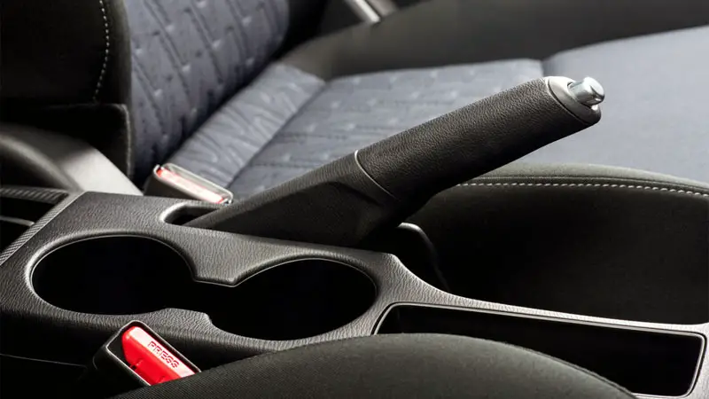
Manual Parking Brakes – These are the traditional systems operated by hand or foot. You might find a lever between the front seats, a pedal near the footrest, or sometimes a handle on the dashboard.
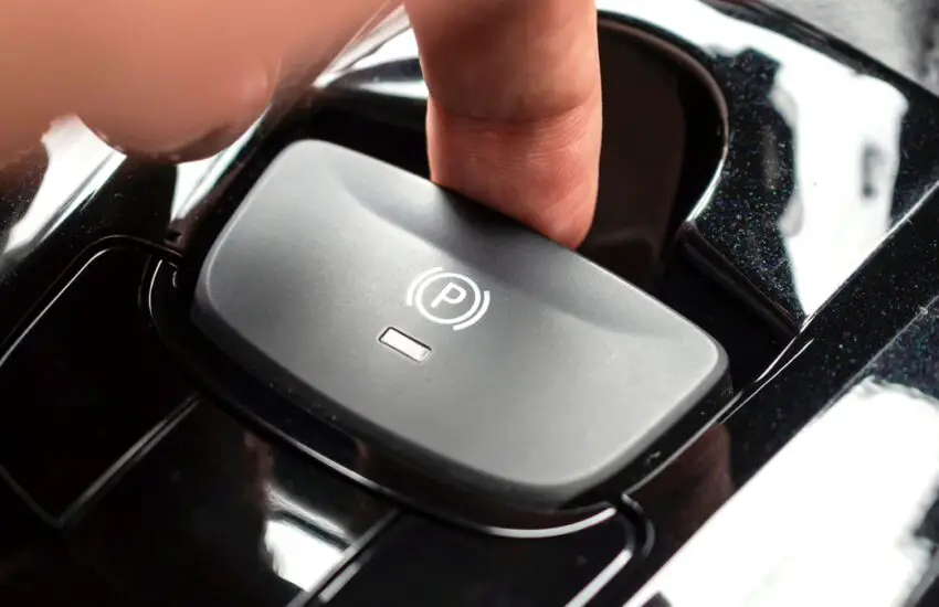
Electronic Parking Brakes (EPB) – More common on newer vehicles, these systems engage with a simple push (or pull) of a button, automatically applying braking force.
Throughout this article, I will specify whether each problem applies to manual systems, electronic systems, or both.
It’s worth noting that the “parking brake” goes by several names. You might also hear it called an emergency brake (e-brake), hand brake, auxiliary brake, or emergency parking brake.
Although these terms are often used interchangeably, they all refer to the same system designed to keep your vehicle stationary when parked.
Common Parking Brake Problems
Now that we have the basics, let’s get into the details of different parking brake problems. I will break down each problem, explain how to spot it, and give you some solutions to try before spending money at the mechanic.
1) Stuck or Frozen Parking Brake (Both Types)
Have you ever tried to release your parking brake and found it stubbornly staying in place? You might have a stuck or frozen brake on your hands. This annoying problem can affect both manual and electronic systems, although the causes may differ.
Symptoms:
The parking brake does not release
You hear a grinding noise when trying to drive
The parking brake warning light stays on even after “releasing” it
How to Fix It:
To start, don’t panic and don’t force it. If you have a manual system, try gently pulling and releasing the lever several times. This might help break up rust or debris causing the jam.
For electronic systems, consult the owner’s manual. Many vehicles have a manual release procedure for emergencies. If that doesn’t work, try turning the car off and on again (yes, really, sometimes for electronic issues, it’s that simple).
If you have frozen brakes due to cold, try letting the car warm up a bit. The engine heat might do the trick.
2) Parking Brake Doesn’t Hold (Both Types)
If after engaging the parking brake, you feel a subtle, disturbing sensation as if your car is still moving forward or backward, the brake isn’t doing its job. Hopefully, you’ll notice this before getting out of the vehicle.
Symptoms:
The car rolls even when the parking brake is fully engaged
You have to leave the car in gear (manual transmission) or turn your wheels against the curb to keep the car in place (even though that’s not a bad idea anyway)
The brake lever/pedal feels loose or doesn’t offer much resistance when engaged
How to Fix It:
First, check if your brake just needs a simple adjustment. For manual systems, you might be able to tighten the parking brake cable yourself. It often just involves turning an adjustment nut (consult your owner’s manual or a service manual).
For electronic systems, a recalibration might be needed, such as holding the switch in the “engage” position for 30 seconds, then in the “disengage” position for another 30 seconds. But don’t be fooled. Be sure to consult a model-specific service manual or do some online research.
If adjustment doesn’t solve the problem, the brake pads/shoes might be worn, the cable stretched, or, in the case of electronic systems, an actuator might be faulty. These issues usually require professional attention.
3) Broken or Frayed Parking Brake Cable (Manual)
You know that satisfying click-click-click when you engage the parking brake? Well, that’s all thanks to a hard-working cable. But like a worn-out rubber band, these cables can stretch, fray, or break over time.
Symptoms:
The parking brake lever lifts too easily
You can pull that lever all the way up and the car still rolls.
The brake releases but won’t engage again
How to Fix It:
Unless you’re an experienced DIYer, it’s best to leave this task to the professionals. Replacing a parking brake cable often requires getting under the car and dealing with hard-to-reach places.
Electronic parking brakes are increasingly common in modern vehicles. Although these systems are convenient and integrate seamlessly with other vehicle functions, they are not immune to malfunctions. When electronic parking brakes fail, the problem often stems from sensor issues or control module errors.
Symptoms:
The parking brake warning light stays on
The brake won’t engage or disengage
You hear the motor running but nothing happens
Your car’s infotainment system throws a fit (i.e., error messages)
How to Fix It:
First, consult the owner’s manual for reset procedures. Sometimes, simply holding the button down for 30 seconds works. If that doesn’t work, you might need to connect a diagnostic tool to see what’s really going on.
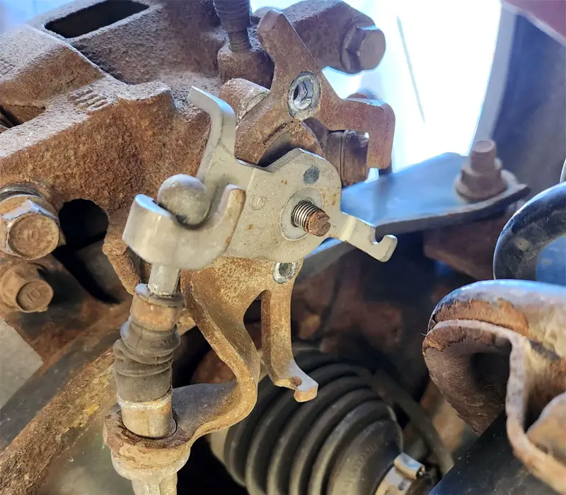
5) Rust and Corrosion (Both Types)
Rust: the silent killer of all things metal, including your trusty parking brake. This sneaky problem can affect both manual and electronic systems, potentially compromising their functionality and reliability. Vehicles in coastal areas or in regions of the country where road salt is used in winter will be most susceptible.
Symptoms:
The parking brake feels sticky or squeaks when you use it
The brake sticks in the engaged or disengaged position
Visible rust on exposed brake components
Squeaking or scraping noise when engaging the brake
How to Fix It:
If you catch it early enough, you might save yourself a hefty repair bill. Try working the brake back and forth to remove light rust. For manual systems, a bit of penetrating oil on the cable can work wonders. Just avoid getting it on the brake pads or shoes.
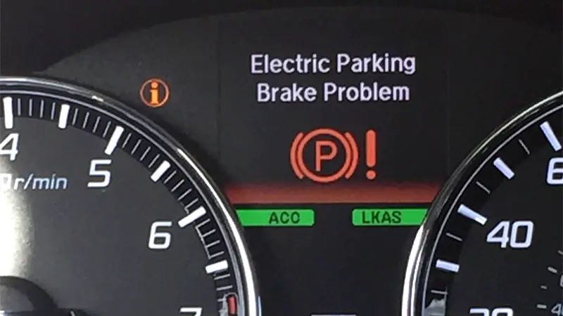
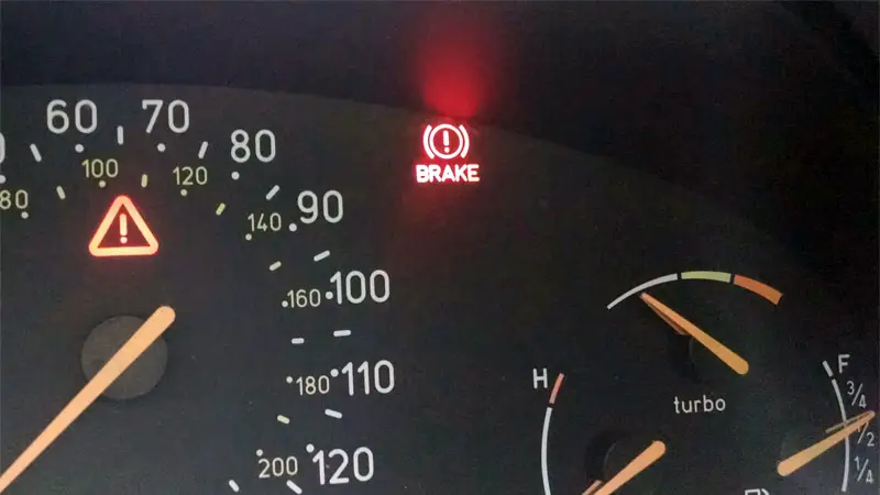
6) Warning Light Problems (Both Types)
Modern vehicles, whether equipped with manual or electronic parking brakes, often have warning lights on the dashboard to indicate the parking brake status or potential problems. These warning lights serve as indicators of system functionality and can signal issues in either type of parking brake mechanism.
Depending on the vehicle manufacturer, these warning lights may include a “P”, “!”, “EPB”, “Service Parking Brake” message, or something else.
Symptoms:
The parking brake warning light stays on even when the brake is not engaged
The light flashes intermittently
The light does not come on when the parking brake is engaged
The light comes on while driving
How to Fix It:
For both types of systems, start by checking if the parking brake is fully released. In manual systems, make sure the lever or pedal is completely released. For electronic systems, try engaging and releasing the brake several times.
If the light persists:
For manual systems – Check the condition of the parking brake cable and ensure it is properly adjusted. Look for any visible damage or excessive play.
For electronic systems – Try completing the parking brake reset procedure or disconnecting the car battery for a few minutes.
If these steps don’t resolve the issue, the problem might lie with the brake switch, wiring, or electronic systems, the control module. At this point, it’s best to use a diagnostic scanner to read error codes or schedule an appointment to have your vehicle inspected.
Q: How often should the parking brake be used?
It is recommended to use the parking brake every time you park your vehicle. Regular use helps maintain the system’s components and prevents issues like rust or seizing mechanisms. It also provides an additional safety measure beyond just putting the transmission in “Park.”
Q: Is the parking brake necessary for vehicles with automatic transmission?
Yes. Although automatic transmissions have a “Park” function, this only locks the transmission. The parking brake provides an extra layer of security, reducing strain on the transmission and ensuring the vehicle remains stationary, especially on slopes.
Q: Can the parking brake be used in an emergency if the primary brakes fail?
The parking brake can serve as an emergency brake in a crisis, but it is not designed for quick stops at high speeds. If used in an emergency, apply steady, increasing pressure and be prepared for reduced braking power compared to the main brakes.
Q: What is the average lifespan of parking brake systems?
With proper use and maintenance, parking brake systems can last the life of the vehicle. However, components may require adjustment or replacement after approximately 100,000 miles, depending on usage habits and environmental factors.
Q: Why did my electronic parking brake make a loud cracking or popping noise after my car sat overnight following a wash?
This noise is usually due to moisture from the wash. Water can accumulate around brake components, causing slight surface rust or minor sticking of the brake pads to the rotors. Upon the first disengagement, this can produce a grinding or popping noise.
Generally, this noise is harmless and goes away almost immediately. However, if the noise persists or affects brake performance, have it checked by a professional. If the noise bothers you, briefly engage and release the parking brake right after washing and before letting the car sit parked.
Check Hybrid System” Warning (5 Causes and How to Reset It)
Hybrid vehicles are equipped with an electric motor and a combustion engine like a traditional vehicle. Hybrid vehicles offer the best of both worlds, using the combustion engine for long range and regenerative braking for increased efficiency in the city.
Although hybrid vehicles offer significant advantages over vehicles equipped solely with a combustion engine or an electric powertrain, they can encounter problems like any other technology.
One such problem is the “check hybrid system” warning light. Here are some tips for troubleshooting this issue.
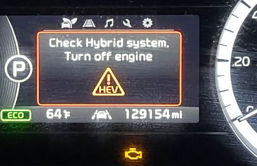
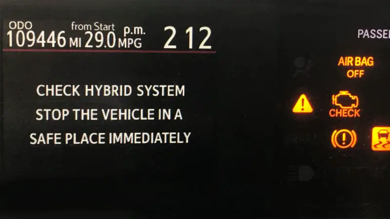
What Does “Check Hybrid System” Mean?
The Check Hybrid System warning indicates that a fault has been detected in the vehicle’s hybrid system. This fault could be related to the battery, a computer managing the hybrid system, or the electric motor.
This message is typically found on the Toyota Prius, but it can also appear on other hybrid vehicles. Sometimes, the problem is as simple as a blown fuse. The warning is usually accompanied by a check engine light.
Causes of the Check Hybrid System Warning
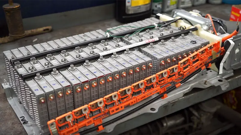
1) Faulty Hybrid Battery
Batteries age over time. They hold less charge and eventually stop working. If you own an older Prius or another hybrid vehicle, it’s highly likely that your hybrid battery will need to be replaced at some point.
Although this is a fairly expensive repair at the mechanic, ChrisFix offers an excellent video on YouTube showing how to replace the hybrid battery yourself if it’s something you’d be comfortable doing.
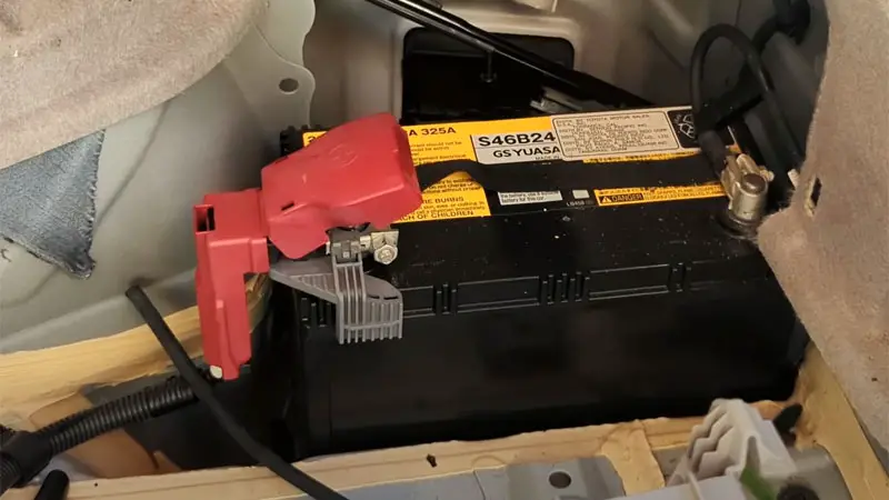
2) Faulty 12V Battery
The 12V battery is a standard car battery and is not specific to hybrid vehicles. Sometimes, a problem with the 12V battery can trigger a Check Hybrid System warning.
If you suspect your 12V battery is faulty, replacing it is quite straightforward. Some auto parts stores may offer a service to do this for you, but it’s also easy for many people to do themselves.
3) Bad Inverter
An inverter converts the direct current from the hybrid battery into alternating current for the electric motor(s). When your inverter fails, your vehicle will no longer be able to properly supply electrical power to the wheels.
4) Wiring Problem
Hybrid systems are equipped with more electrical components, which means more wiring and grounding points. A broken wire or a bad ground can trigger a warning light or render the hybrid system unusable.
To search for a faulty wire, it’s always best to have a manufacturer-provided wiring diagram on hand. Some vehicles may be prone to corrosion or poor wiring in certain areas. When rodents get into your vehicle, they sometimes chew on wires, which can also cause faults and error codes.
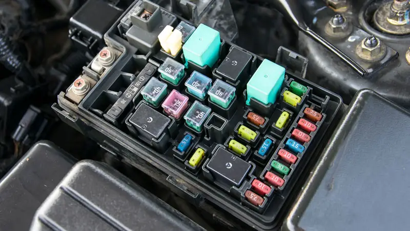
5) Blown Fuse
A blown fuse is the simplest and cheapest fix for a warning light. So always check for blown fuses when troubleshooting an issue. Most fuse boxes are located either in the vehicle’s floor area or under the hood.
Can You Drive with the “Check Hybrid System” Message?
There are many cases where your car stalls while driving and fails to start with the gasoline engine alone when you see this message. In this case, you may need to address the root cause of the problem or at least reset the warning to get your vehicle started again.
If your car is operating normally, you can often continue driving safely even with the light on. Of course, this will depend on the exact cause of the problem.
If you have doubts about your vehicle’s safety, it’s always best to take it to a qualified mechanic. Sometimes, they can perform a quick diagnostic to assess the vehicle’s roadworthiness.
How to Reset the Check Hybrid System Warning
Turn off the vehicle, lift the hood, and open the trunk. You will find the hybrid battery in the trunk, near the spare wheel. On the hybrid battery, there is an orange safety switch. Remove it by sliding the handle towards the left side of the vehicle, then pulling it outward.
Next, go to the hood and open the fuse box. You should see a large wire with a white connector at the end. Disconnect the white connector from the fuse box.
Wait 10 minutes with both components disconnected, then reinstall them in the reverse order. Turn the engine on and off 3 times. This should make the warning light disappear in many cases. If your warning light did not turn off, you may have a more permanent issue with your battery or hybrid system.
Note that this does not necessarily fix the root cause of your problem. So don’t be surprised if the warning light comes back on in the future. The Check Hybrid System light can come on because you have a battery that is still working intermittently but is about to fail.