P005E Turbo/Supercharger Boost Control B Low Voltage

Code P005E: Definition and Explanation

The diagnostic trouble code P005E is a generic OBD-II powertrain code that indicates a low voltage value in the boost control B supply voltage circuit. It applies to many vehicles, including Chevrolet, GMC Duramax, Dodge, Ram Cummins, Isuzu, Ford, Vauxhall, and VW. Precise diagnostic steps may vary by brand, model, year, and engine configuration.

Role of the Boost System

Forced induction systems (turbocharger, supercharger) use engine energy (exhaust gases, belt drive) to increase the amount of air entering the combustion chambers, thereby improving volumetric efficiency and power.

To regulate boost pressure, a control module (often called a wastegate or control solenoid) mechanically adjusts the turbocharger vanes. This system is managed by the Engine Control Module (ECM) to maintain an optimal stoichiometric air-fuel mixture. The letter “B” typically distinguishes a specific circuit, connector, or group within the system.

Severity of Code P005E

The severity is moderate to high. A fault in the boost control system can lead to a dangerous air-fuel mixture (too rich or too lean), causing power loss, excessive fuel consumption, and potentially serious engine damage. The ECM often triggers a limp mode (safe mode) to protect the engine, drastically limiting performance.

Common Symptoms of P005E Fault

  • Noticeable and irregular power loss
  • Abnormal response during acceleration
  • Difficulty climbing hills
  • Activation of safety mode (limp mode)
  • Excessive fuel consumption
  • Intermittent poor driving symptoms

Possible Causes of Code P005E

  • Faulty boost control solenoid (stuck, broken lever)
  • Corrosion or poor contact in connectors, pins, or grounds
  • Wiring issue (frayed wires, open circuit, short circuit)
  • Internal ECM failure
  • Soot buildup on turbocharger vanes
  • Boost control module problem
  • Exhaust system leak

Diagnostic Procedure for Code P005E

Step 1: Visual and Mechanical Inspection

WARNING: The engine and turbocharger can be extremely hot. Ensure the engine is cool before any intervention.

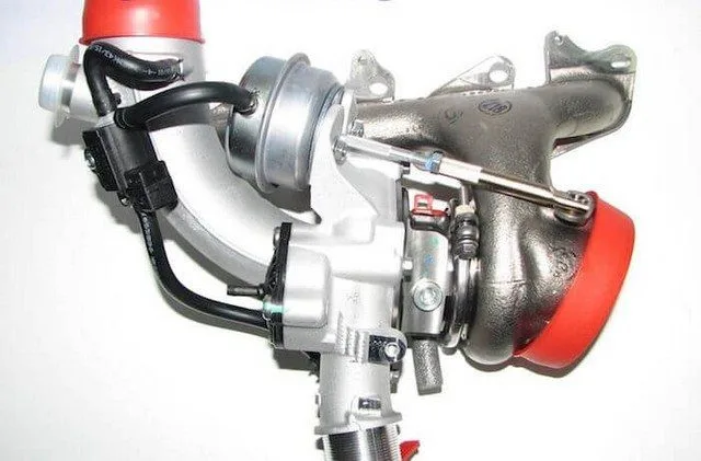
Locate the boost control solenoid (usually mounted on the turbocharger). Check that its lever moves freely without being stuck, broken, or bent. On some models, the lever is adjustable.

Step 2: Connector and Seal Check

Inspect the solenoid’s electrical connector and the control module for any signs of corrosion, water intrusion, or physical damage. A corroded assembly will most likely need replacement.

Step 3: Wiring Inspection

Follow the wiring harness connecting the solenoid to the ECM. Look for any signs of heat damage, frayed wires, or burns. Cables are often routed near intense heat sources.

Step 4: Advanced Diagnostics

For accurate diagnosis, using a scan tool is necessary to check the voltage and resistance values of the “B” control circuit. Consult manufacturer-specific technical data (wiring diagram) for reference values. If in doubt, entrust the diagnosis to a professional mechanic.

Conclusion and Call to Action

Code P005E should not be ignored. A faulty boost system can lead to costly repairs. If you are not comfortable with these diagnostic steps, immediately consult a specialized garage for a thorough diagnosis and reliable repair.

P005F Turbo/Supercharger Boost Control B Voltage High

Code P005F: High Voltage in Boost Pressure Control Circuit B

The generic diagnostic trouble code P005F falls under the powertrain category. It indicates that the Engine Control Module (ECM) has detected an abnormally high voltage in the boost pressure control “B” circuit. This code primarily affects vehicles equipped with a turbocharger or a supercharger (forced induction).

Role of the Boost Pressure Control System

Forced induction systems use exhaust gas energy (turbocharger) or a belt drive (supercharger) to increase the amount of air entering the cylinders, thereby enhancing engine power.

To precisely regulate boost pressure, the ECM controls an actuator – often a solenoid or a wastegate valve. This system helps maintain an optimal (stoichiometric) air-fuel mixture. If the ECM loses control over this pressure, it may put the engine into a reduced power mode (“limp mode”) to prevent serious damage.

Severity of Code P005F

The severity is moderate to high. A fault in the boost pressure control circuit can lead to an imbalanced air-fuel mixture, significant power loss, increased fuel consumption, and, in extreme cases, engine damage. It is recommended to perform diagnostics as soon as possible.

Common Symptoms

  • Engine power loss (limp mode)
  • Abnormal response during acceleration
  • Increased fuel consumption
  • Irregular engine operation
  • Malfunction Indicator Light (MIL) illumination

Possible Causes

  • Faulty wastegate solenoid or actuator (stuck or broken lever)
  • Wiring issue (short to ground or power, broken wire)
  • Oxidized, corroded, or loose electrical connectors
  • Internal failure of the Engine Control Module (ECM)
  • Clogged turbocharger vanes (soot buildup)
  • Leak in the exhaust or intake circuit

Basic Diagnostic Steps

⚠️ Warning: Boost system components become extremely hot. Only work on a cold engine and wear protective equipment if necessary.

  1. Visual Inspection: Locate the boost control solenoid (usually mounted on the turbo). Check the physical condition of the actuator lever and its movement (it should move manually without binding).
  2. Connector Inspection: Carefully inspect the solenoid’s electrical connector. Look for any signs of corrosion, oxidation, burning, or moisture.
  3. Wiring Inspection: Trace the wiring harness connected to the solenoid. Check for frayed, melted, or heat-damaged wires.
  4. Electrical Measurements: Using a multimeter, check the circuit voltage and continuity according to manufacturer specifications. Look for a short to +12V that would explain the high voltage.

Tip: Technical specifications (voltage values, resistance) vary significantly between manufacturers. Consulting the vehicle-specific technical documentation is essential for accurate diagnosis.

Conclusion and Call to Action

Code P005F indicates a serious electrical problem in the boost pressure management system. While some basic checks can be performed by a skilled DIYer, accurate fault diagnosis often requires the expertise and equipment of a professional.

Experiencing this issue? Avoid damaging your engine. Consult a qualified mechanic for a thorough diagnosis and reliable repair.

P0060 HO2S Heater Resistance, Bank 2 Sensor 2

What is the P0060 Code?

The P0060 trouble code is a generic powertrain code. It indicates a malfunction in the heater circuit of the downstream oxygen sensor (lambda sensor) located after the catalytic converter (sensor 2) on the bank of cylinders that does not contain cylinder number 1 (bank 2). This issue can affect most OBD-II equipped vehicles (Chevrolet, Ford, GMC, Mazda, Pontiac, Isuzu, etc.), although specific diagnostic procedures may vary by make and model.

Function of the Lambda Sensor and Its Heater Circuit

The lambda sensor measures the proportion of oxygen in the exhaust gases. Its integrated heating element allows for rapid warm-up to ensure optimal operation, especially when cold. The Powertrain Control Module (PCM) continuously monitors the resistance of this heater circuit. The P0060 code is triggered when the measured resistance exceeds the programmed tolerance values in the PCM.

Symptoms of the P0060 Code

This fault is considered serious because it affects the air-fuel mixture, particularly during cold starts. Common symptoms include:

  • Hard starting in cold weather
  • Increased fuel consumption
  • Black smoke from the exhaust (overly rich mixture)
  • Illumination of the Malfunction Indicator Lamp (MIL)
  • Possibility of related trouble codes

Possible Causes of the P0060 Fault

Several components can be the source of this code:

  • Damaged wiring (chafing, burning, cutting) or an oxidized/disconnected connector
  • The lambda sensor itself is faulty (heater element failure)
  • A blown fuse or a faulty relay supplying the heater circuit
  • A problem with the PCM (less common)

Diagnosis and Solutions for Resolving the P0060 Code

Preliminary Tip: Consult your manufacturer’s Technical Service Bulletins (TSBs). This might be a known issue with a specific correction procedure.

Recommended Diagnostic Steps:

  1. Visual Inspection: Meticulously examine the sensor’s wiring and connectors, especially sections exposed to heat (exhaust) or sharp edges.
  2. Checking Fuses and Relays: Test all fuses and the relay associated with the lambda sensor heater circuit with a multimeter, under load to avoid false positives.
  3. Using an OBD2 Scanner:
    • Read and note all present trouble codes.
    • Clear the codes and perform a road test to see if the P0060 returns immediately.
    • On a cold engine, observe the scanner’s live data regarding the heater circuit status. The voltage should be close to battery voltage (≥12.6V).
  4. Electrical Tests with a Multimeter (DVOM):
    • Measure voltage and continuity on the circuit.
    • Measure the resistance of the lambda sensor’s heating element (refer to the manufacturer’s specifications). Always disconnect the connector before taking this measurement.

Note: A repeatedly blowing fuse typically indicates a short circuit in the heater circuit.

Conclusion and Call to Action

Diagnosing the P0060 code requires a methodical approach, starting with the simplest checks (fuses, wiring). If the problem persists after these checks, replacing the lambda sensor is often the solution.

Don’t feel comfortable performing these procedures? Entrust the diagnosis and repair of your vehicle to a certified professional. They have the necessary tools and expertise to resolve the issue effectively and guarantee the repairs.

P0061 HO2S Heater Resistance, Row 2, Sensor 3

What is the P0061 code?

The P0061 error code is a generic powertrain-related code. It indicates that the Powertrain Control Module (PCM) has detected an abnormal resistance in the heater circuit of oxygen sensor (lambda sensor) #3, located downstream of the catalytic converter on bank 2 (the engine side that does not contain cylinder #1). This fault prevents the sensor from reaching its operating temperature quickly, disrupting proper engine operation, especially when cold.

Symptoms and Severity of the Fault

This code is considered serious and should not be ignored. Common symptoms include:

  • ❄️ Hard starting in cold weather
  • ⛽ Engine overheating or excessive fuel consumption
  • ⚫ Black smoke from the exhaust (rich fuel mixture)
  • ⚠️ Illumination of the Malfunction Indicator Lamp (MIL)
  • 📟 Possible appearance of other related fault codes

Possible Causes of the P0061 Code

Several components can be the source of this problem:

  • 🔌 Damaged, loose, or corroded wiring
  • 🛠️ Faulty O2 sensor (heater element failure)
  • ⚡ Blown fuse or faulty relay
  • 🔋 Ground or power supply voltage issue

Diagnosis and Solutions

Before any intervention, consult your manufacturer’s Technical Service Bulletins (TSBs) to check if the problem is known and subject to a recall or specific procedure.

Recommended Diagnostic Steps:

  1. Visual Inspection: Check the condition of the wires and connectors, especially near hot parts (exhaust) or sharp edges.
  2. Fuse Check: Test the relevant fuses and relays with a multimeter, under load to avoid false positives.
  3. Using an OBD2 Scanner: Read the fault codes and live data. Observe the heater circuit voltage of the sensor when the engine is cold. It should be close to the battery voltage.
  4. Resistance Test: Using a multimeter, measure the resistance of the lambda sensor’s heating element (refer to the manufacturer’s specific values). Remember to disconnect the connectors before any measurement.

Common Repairs:

  • Replace the faulty oxygen sensor (this is often the solution)
  • Repair or replace the damaged wiring harness
  • Replace a blown fuse or faulty relay

Important Tip: After repair, clear the codes and perform a drive cycle so the PCM can recalibrate the values and turn off the MIL.

Conclusion

The P0061 code indicates a serious problem with your lambda sensor’s heater circuit. Accurate diagnosis helps avoid unnecessary part replacement. If you are not comfortable with these procedures, consult a professional mechanic for a reliable diagnosis.

💡 Need Help? Share your vehicle’s exact model and any additional fault codes in the comments to get more precise advice!

P0062 Heated Oxygen Sensor Control Circuit Bank 2 Sensor 3

What is the P0062 Code?

The P0062 error code is a generic OBD-II code related to the powertrain. It indicates a malfunction in the heater control circuit of the heated oxygen sensor (HO2S), specifically the third downstream sensor (B2S3) on engine bank 2. This code applies to most vehicles (from 1996 onwards), including brands like Volkswagen, Ford, GM, Dodge, and many others.

Role of the Oxygen Sensor and Its Heater

Modern vehicles use heated oxygen sensors to monitor the oxygen content in exhaust gases, both before and after the catalytic converter. Their feedback allows the engine control module (PCM/ECM) to continuously adjust the air/fuel mixture to maintain an optimal ratio of 14.7:1, which is essential for performance and emission control.

The integrated heater circuit in the sensor allows it to reach its operating temperature more quickly, especially during a cold start, ensuring accurate data from the beginning.

Symptoms of the P0062 Code

  • Illumination of the Malfunction Indicator Lamp (MIL) on the dashboard.
  • No other visible symptoms (loss of power, increased fuel consumption) are common, as the heater mainly functions during startup.
  • In the long term, a faulty sensor can prevent monitoring of the catalytic converter’s efficiency, potentially leading to a failure in emissions testing.

Possible Causes of the P0062 Fault

  • Internal sensor failure: Heater circuit open inside the HO2S sensor.
  • Wiring problem: Damaged, corroded, or loose power or ground wires in the heater circuit.
  • Poor ground: Corrosion or break in the exhaust system ground strap (for 3-wire sensors).
  • Control module (PCM/ECM) failure: A rare but possible failure of the control circuit within the module.

Diagnosis and Solutions for Repairing the P0062 Code

⚠️ Safety First: Always allow the exhaust system to cool completely before any intervention to avoid serious burns.

  1. Visual Inspection: Examine the wiring and connector of the B2S3 sensor for any obvious signs of damage, corrosion, or debris.
  2. Heater Resistance Test:
    • Disconnect the oxygen sensor connector.
    • Using a multimeter (DVOM) in Ohms (Ω) mode, measure the resistance between the heater circuit pins (refer to the repair manual to identify the pins).
    • Infinite resistance (OL) or a reading outside specifications indicates a faulty sensor that needs replacement.
  3. Ground Test: With the multimeter in Ohms mode, check for continuity between the ground pin of the connector and a known good chassis ground. A lack of continuity indicates a wiring or grounding issue.
  4. Power Supply Test:
    • Reconnect the sensor and use the multimeter in DC Volts mode.
    • During a cold start, probe the heater’s power supply wire (refer to the manual).
    • Battery voltage (approx. 12V) should be present briefly. Its absence points to a wiring or PCM problem.

Conclusion and Call to Action

Although the P0062 code does not directly affect driving, it should not be ignored. A faulty oxygen sensor can mask a more serious problem with the catalytic converter. If the diagnostic steps are beyond your skills, consult a professional mechanic for an accurate diagnosis and reliable repair. Use a quality OBD2 scanner to confirm the code and clear the warning light after repair.

P0063 Heater Control Circuit Low B2S3 HO2S

What is the P0063 Code?

The diagnostic trouble code P0063 is a generic powertrain code. It applies to most vehicles from 1996 and newer. It indicates a problem with the heater control circuit of the Heated Oxygen Sensor (HO2S) for Bank 2, Sensor 3.

Role of the HO2S Sensor

Heated Oxygen Sensors (HO2S) are essential components used by the Powertrain Control Module (PCM) to analyze the oxygen content in the exhaust gases. The specific “Bank 2, Sensor 3” sensor is primarily used to monitor the efficiency of the catalytic converter. An integrated heating element allows it to quickly reach its optimal operating temperature, which reduces emissions during cold starts and enables the engine to enter closed-loop operation faster.

Heater Circuit Operation

The PCM controls the sensor heater in two main ways, depending on the manufacturer:

  • The PCM directly controls the voltage supply (via a relay or not), while the ground is provided by the vehicle’s chassis.
  • A constant 12-volt supply (B+) is provided to the sensor, and the PCM controls the circuit by managing the ground through an internal driver.

The P0063 code is triggered when the PCM detects an abnormally low voltage on this control circuit. Bank 2 refers to the side of the engine that does not contain cylinder number 1.

Symptoms of the P0063 Code

Symptoms are often subtle but may include:

  • Illumination of the Malfunction Indicator Lamp (MIL) on the dashboard.
  • A slight increase in pollutant emissions.
  • Generally, no noticeable driving symptoms are felt.

Possible Causes of the Fault

Several elements can cause the P0063 code:

  • Failure of the heating element in the oxygen sensor (Bank 2, Sensor 3).
  • Physically damaged HO2S sensor (impact, corrosion).
  • Control circuit shorted to ground or faulty power circuit.
  • Internal PCM failure (the heater control driver is faulty).
  • Damaged electrical wires, cut or melted near the exhaust.

Diagnosis and Possible Solutions

To diagnose and resolve a P0063 code, follow these steps:

1. Visual Inspection

Perform a thorough inspection of the sensor (Bank 2, Sensor 3) and its wiring harness. Look for signs of burning, friction, or physical damage. Ensure the wiring is properly routed and away from hot exhaust parts. If damage is visible, repair or replace the affected components.

2. Electrical Test

Disconnect the HO2S sensor connector. With the ignition on (engine off), check for the presence of:

  • Either a 12-volt supply at the connector (depending on the system).
  • Or a ground control managed by the PCM (using a multimeter).

This will tell you which type of circuit your vehicle uses and allow you to verify its integrity.

3. Sensor Test

If the wiring is intact, remove the sensor and inspect its sensing element for contamination or damage. Using a multimeter in ohmmeter mode, measure the resistance of the sensor’s heating element according to the manufacturer’s specifications. An infinite resistance (open circuit) or zero resistance (short circuit) confirms sensor failure. In this case, replacement of the oxygen sensor is necessary.

4. Replacement and Reset

After replacement, use a diagnostic tool to clear the P0063 trouble code from the PCM’s memory and perform a drive cycle to verify that the fault does not reappear.

Conclusion

The P0063 code often points to an electrical problem in the heater circuit of a specific oxygen sensor. Although symptoms are often minor, it is important to repair it to ensure the proper functioning of the emissions control system and avoid potential failure during an emissions test.

⚠️ Pro Tip: Accurate diagnosis often requires a multimeter and specification data. If you are not comfortable with these procedures, it is recommended to consult a professional mechanic for an accurate diagnosis.

P0064 High HO2S Heater Control Circuit (Bank 2 Sensor 3)

What is the P0064 Code?

The P0064 trouble code is a generic powertrain code (OBD-II). It indicates a problem with the heater control circuit of the Heated Oxygen Sensor (HO2S) located at Bank 2, Sensor 3. This fault specifically concerns the heating part of the sensor and not its exhaust gas measurement function.

Role of the HO2S Sensor and Its Heater

The Heated Oxygen Sensor (HO2S) is a crucial component of the engine management system. The Powertrain Control Module (PCM) uses data from the Bank 2, Sensor 3 primarily to monitor the efficiency of the catalytic converter.

The heater element integrated into the sensor allows it to reach its optimal operating temperature more quickly. This reduces the time needed to reach “closed loop” operation, which is essential for precise emission control and optimal air-fuel mixture. The PCM continuously controls and monitors the heater circuit to detect any voltage or current anomalies.

Symptoms of the P0064 Code

Symptoms are often subtle. You might observe:

  • Illumination of the Malfunction Indicator Lamp (MIL) on the dashboard.
  • A slight increase in fuel consumption.
  • Potentially higher pollutant emissions.
  • Generally, no noticeable driving symptoms (loss of power, misfires) are felt.

Possible Causes of the P0064 Fault

Several causes can be at the origin of this code:

  • Faulty O2 Sensor: The internal heater element of the Bank 2, Sensor 3 sensor is burnt out or faulty.
  • Wiring Problem: Damaged, chafed, melted, or corroded cables, especially near the sensor or the exhaust.
  • Short Circuit: The heater control circuit is shorted to ground (ground-controlled systems) or to power (B+).
  • Open Circuit: A break in the heater’s power, ground, or control wire.
  • PCM Problem: An internal failure of the engine control module is rare, but possible.

Diagnosis and Solutions to Repair the P0064 Code

⚠️ Warning: Always work on a cold engine to avoid any risk of burns.

1. Visual Inspection

Start with a thorough inspection of the Bank 2, Sensor 3 sensor and its wiring harness. Look for obvious signs of damage: melted wires, burnt insulation, oxidized or loose connector. Ensure the wiring is properly routed and away from hot engine parts and the exhaust line.

2. Electrical Check of the Sensor

Disconnect the HO2S sensor connector. Using a multimeter, measure the resistance across the terminals of the heater element (usually the two wires of the same color, often white). Consult manufacturer data for the expected resistance value. An infinite resistance (OL) indicates an open heater element: the sensor must be replaced.

3. Circuit Check

With the connector disconnected and the ignition on (engine off), check for the presence of:

  • For +12V controlled systems: Measure the voltage on the heater power wire. You should find +12V. Check the integrity of the ground wire.
  • For ground-controlled systems: Check for the presence of constant +12V on one heater wire. The PCM controls the ground on the other wire.

If power and ground are correct but the fault persists, the sensor is very likely faulty. If power or ground is absent, look for a wiring or fuse problem.

4. Replacing the O2 Sensor

If all checks point to a faulty oxygen sensor, proceed with its replacement. Use a suitable deep socket wrench to loosen the old sensor. Apply anti-seize compound to the threads of the new sensor (if it is not pre-greased) and tighten it to the torque specified by the manufacturer. Reconnect the electrical connector.

5. Clearing Codes

After repair, use an OBD2 diagnostic scanner to clear the trouble code from the PCM’s memory. Perform a drive cycle to ensure the code does not reappear.

Conclusion

The P0064 code is often caused by a faulty oxygen sensor or its wiring. Although it doesn’t always affect driving, it must be corrected to ensure the proper functioning of the anti-pollution system and avoid a potential failure during an emissions test.

Call to Action: Electrical diagnosis requires specific skills. If you do not feel comfortable with these procedures, entrust the diagnosis and repair to a professional mechanic.

P0065 Performance of the Pneumatic-Assisted Injector Control Range

Code P0065: Air Assisted Injector Control Range Performance

What is code P0065?

The generic diagnostic trouble code (DTC) P0065 is a powertrain code that applies to vehicles equipped with an air assisted fuel injector. While present on various brands (Subaru, Jaguar, Chevy, Dodge, VW, Toyota, Honda), it primarily appears on Subaru and Jaguar models. Specific repair steps may vary by brand, model, and engine.

How the Air Assisted Injector Works

Similar to a conventional injector, the air assisted injector uses air to optimize fuel atomization during injection. This system is typically activated during cold starts, when the engine requires a richer air/fuel mixture. Uniform spraying is crucial, as a single injector mounted on the throttle body or intake often supplies multiple cylinders.

Cause and Triggering of the Code

The ECM (Engine Control Module) activates the check engine light and records code P0065 when it detects an anomaly in the air assisted injector circuit. This is usually an electrical issue, but an internal injector malfunction can also be the cause. This code is often associated with DTCs P0066 and P0067.

Severity of Code P0065

The severity is moderate. The code does not affect engine performance at normal operating temperature, but repeated cold starts with a too lean mixture can cause long-term damage. Therefore, repair is recommended.

Common Symptoms

  • Hard starting in cold weather
  • Exhaust smoke
  • Poor cold performance
  • Misfires
  • Excessive fuel consumption

Possible Causes

  • Damaged wiring harness
  • Vacuum leak at the injector or pipes/clamps
  • Faulty fuse or relay
  • Defective air assisted injector
  • ECM problem
  • Corrosion or overheating of pins/connectors

Required Tools

  • OBD-II code reader
  • Multimeter
  • Socket and wrench set
  • Screwdriver
  • Battery terminal cleaner
  • Repair manual

Safety Tips

  • Let the engine cool down before working
  • Use wheel chocks to block the wheels
  • Wear personal protective equipment (PPE)

Diagnostic Steps

1. Check Technical Service Bulletins (TSBs)

Check TSBs for your vehicle. A known fix may simplify diagnosis.

2. Inspect for Vacuum Leaks

Locate the injector (usually on the throttle body) by consulting the manual. Inspect pipes and seals for possible leaks. With the engine running, listen for abnormal hissing sounds. Use a vacuum gauge to measure intake vacuum and compare it to specifications.

Tip: Replace any cracked hoses to avoid future problems.

3. Electrical Test of the Injector

Measure the resistance at the injector terminals with a multimeter. Refer to the manual for reference values.

Caution: Use appropriate connectors to avoid damaging the pins.

4. Inspect Connectors

Check the injector’s electrical connector for corrosion or defects. Inspect the condition of the harness and its routing to avoid chafing.

Important: Always disconnect the battery before any electrical work.

5. Circuit Test

Test the continuity of the wires between the injector and the ECM with a multimeter. Perform a voltage drop test to check circuit integrity.

6. Real-World Condition Test

If your diagnostic tool allows, monitor the injector’s operation while driving to compare actual values with expected values.

Conclusion

Code P0065 indicates a problem with the air assisted injector. Although not critical, it requires investigation to avoid future complications. If the diagnostic steps exceed your skills, consult a professional mechanic for reliable repair.

P0066 Air Assisted Injector Control Circuit or Circuit Low

What is the P0066 Code?

The error code P0066 is a generic powertrain code. It indicates a malfunction in the air-assisted injector control circuit or a low circuit. This code primarily affects Subaru and Jaguar vehicles but can also appear on other brands (Chevy, Dodge, VW, Toyota, Honda) equipped with a pneumatic injection system. Diagnostic steps may vary depending on the manufacturer and model.

Function of the Air-Assisted Injector

The air-assisted injector optimizes fuel atomization by introducing air into it, which improves the spray and distribution of the air-fuel mixture. It is mainly used during cold starts, when the engine requires a richer mixture. A fault in its circuit can disrupt this process.

Severity and Symptoms of the P0066 Code

The severity of this code is moderate. Although it generally does not affect engine performance when warm, it can cause:

  • Difficult cold starts
  • Excessive smoke from the exhaust
  • Misfires and poor acceleration
  • Increased fuel consumption
  • Poor performance in cold weather

Failure to repair it can eventually damage the engine.

Possible Causes of the P0066 Code

  • Broken or damaged wires in the wiring harness
  • Vacuum leak at the injector, pipes, or clamps
  • Faulty fuse or relay
  • Defective air-assisted injector
  • Connector issue (corrosion, overheating)
  • Failure of the ECM (Engine Control Module)

Tools Required for Diagnosis

  • OBD2 diagnostic tool
  • Multimeter for electrical tests
  • Set of sockets and wrenches
  • Set of screwdrivers
  • Electrical contact cleaner
  • Vehicle-specific repair manual

Safety Tips

  • Let the engine cool down before any intervention.
  • Wear personal protective equipment (PPE).
  • Chock the vehicle’s wheels.
  • Disconnect the battery before working on the electrical circuit.

Diagnostic Procedure for the P0066 Code

1. Checking for Vacuum Leaks

Locate the air-assisted injector (usually mounted on the throttle body). With the engine running, listen for abnormal hissing sounds indicating an air leak. Visually inspect the pipes and clamps. Replace any cracked or worn components.

2. Electrical Test of the Injector

Using a multimeter, measure the resistance at the injector terminals. Compare the reading with the value specified in the repair manual. An out-of-range value indicates a faulty injector.

3. Inspection of Connectors and Wiring

Inspect the injector’s electrical connector for corrosion, bent pins, or damage. Check the condition of the wiring harness along its entire length to identify any chafing or wear.

4. Circuit and ECM Testing

Test the continuity of the wires between the injector and the ECM using the multimeter. Perform a voltage drop test to verify the integrity of the circuit. If everything is normal, an issue with the ECM itself is possible.

5. Using an Advanced Diagnostic Tool

If your scan tool allows it, activate the air-assisted injector and monitor its real-time data (control parameters) to identify any operational anomalies.

Conclusion and Call to Action

The P0066 code is often related to a simple electrical issue, such as a bad connector or a cut wire. However, accurate diagnosis is essential to avoid unnecessary part replacements.

Having trouble diagnosing this code? Consult a professional equipped with a diagnostic tool suitable for your vehicle without delay. Use a specific repair manual to obtain the correct resistance values and procedures for your model.

P0067 High Air Assisted Injector Control Circuit

What is the P0067 code?

The diagnostic code P0067 is a generic powertrain code. It indicates an electrical problem in the air assisted injector control circuit. Although it can appear on various brands (Subaru, Jaguar, VW, Toyota, etc.), it is primarily encountered on Subaru and Jaguar vehicles. Repair steps may vary depending on the model.

Function of the Air Assisted Injector

This injector uses air to improve fuel atomization, which is crucial for cold starts. A cold engine requires a richer air/fuel mixture. The introduced air allows for a finer and more uniform spray, optimizing fuel distribution to the cylinders.

Why the Code Illuminates

The Engine Control Module (ECM) detects an abnormally high electrical value in the circuit and triggers the check engine light. This code is often associated with codes P0065 and P0066.

Severity of the P0067 Code

The severity is moderate. The vehicle will operate normally once the engine is warm, but difficult cold starts with a lean mixture can cause long-term damage. Repair is recommended.

Symptoms of the P0067 Code

  • Hard starting in cold weather
  • Exhaust smoke
  • Poor engine performance when cold
  • Misfires
  • Increased fuel consumption

Possible Causes of the P0067 Code

  • Damaged or cut wiring harness
  • Vacuum leak at the injector or pipes/clamps
  • Faulty fuse or relay
  • Faulty air assisted injector
  • Problem with the ECM
  • Corrosion or overheating of pins/connectors

Tools Needed for Diagnosis

  1. OBD2 scanner
  2. Digital multimeter
  3. Socket and wrench set
  4. Screwdriver set
  5. Electrical contact cleaner
  6. Vehicle repair manual

Safety Instructions

  • Let the engine cool down before any work.
  • Chock the vehicle’s wheels.
  • Wear personal protective equipment (safety glasses, gloves).
  • Always disconnect the battery before working on the electrical circuit.

Diagnostic Procedure for Code P0067

Step 1: Checking for Vacuum Leaks

Consult the manual to locate the injector (often on the throttle body). With the engine running, listen for any abnormal hissing indicating an air leak. Visually inspect the intake pipes and seals. Replace any cracked or worn hoses.

Step 2: Injector Test

Using a multimeter, measure the resistance across the injector terminals. Compare the obtained value with that specified in the repair manual. A significant deviation indicates a faulty injector.

Tip: Use appropriate multimeter connectors to avoid damaging fragile pins.

Step 3: Connector and Wiring Inspection

Inspect the electrical connector of the injector for any corrosion, overheating, or damage. Check the condition of the wiring harness along its entire length to identify potential chafing or wear.

Step 4: Electrical Circuit Test

Test the continuity and resistance of the wires between the injector and the ECM. A voltage drop test can also reveal poor circuit integrity.

Step 5: Real-World Condition Test (if possible)

If your scan tool allows it, activate the air assisted injector and monitor its operating values in real-time. Compare them with the target values.

Step 6: Checking Technical Service Bulletins (TSB)

Before replacing parts, consult your vehicle’s Technical Service Bulletins (TSB). The manufacturer may have issued a known fix for this specific problem, saving you time and money.

Conclusion and Call to Action

Diagnosing the P0067 code requires a methodical approach, starting with the simplest checks (leaks, connectors). If the troubleshooting steps above do not resolve the issue, it is highly recommended to consult a professional mechanic with the expertise and diagnostic equipment specific to your vehicle model.