Wheel bearings play an important role in reducing friction, increasing load capacity, and positioning rotating equipment. Moreover, car bearings also help wheels operate smoothly and increase their lifespan. To ensure the proper functioning of wheel bearings, drivers must know all about this part.
Wheel Bearing Standards.
Wheel bearings fulfill the important task of reducing vibrations, decreasing wear, preventing shocks, and evenly distributing the car’s load. Therefore, this component must meet various standards in terms of speed, performance, and lifespan.
Bearings are typically made of steel because this material has high durability and the ability to withstand significant operating loads. The higher the quality and heat resistance of the steel, the longer the bearing’s lifespan. Additionally, manufacturers also focus on designing compact bearings for easy installation while ensuring reliability and rigidity, suitable for many different car models.
How many wheel bearings does a car have?
There are 2 commonly used types of car wheel bearings: ball bearings and roller bearings. Each type of bearing has its characteristics, suited to each car to meet load and application requirements.
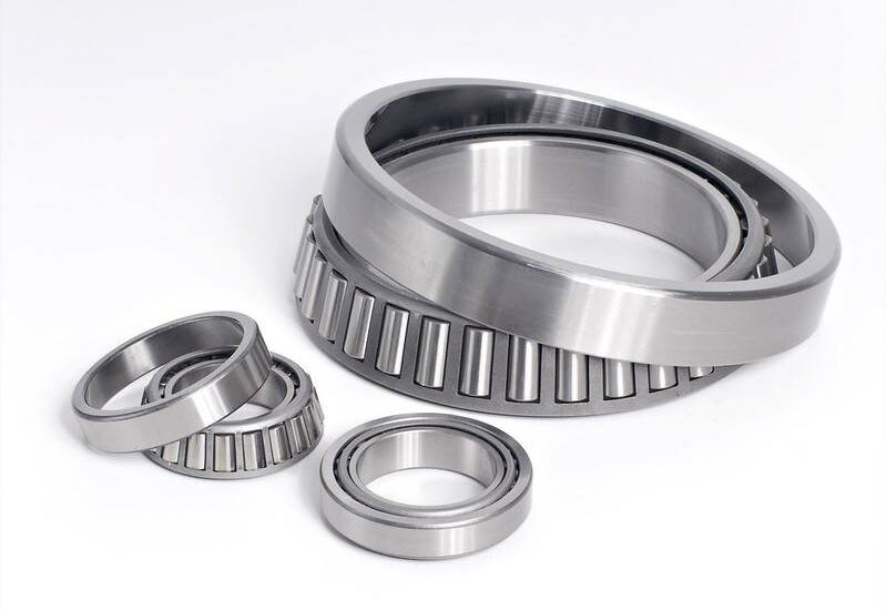
Tapered Roller Bearings
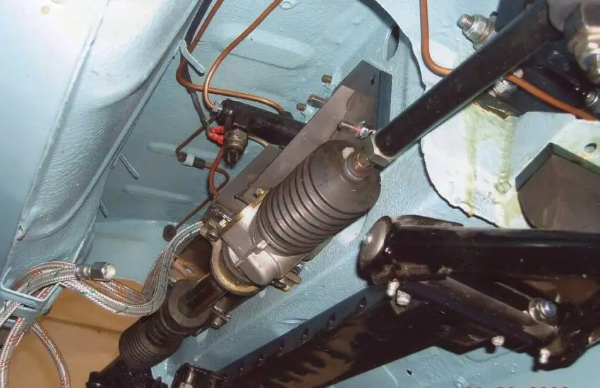
Tapered roller bearings are composed of two main separable parts, an inner ring and an outer ring. During operation, the tapered roller moves around the raceway in the inner and outer rings. The bearings have very high axial and radial load capacity. Therefore, this type of bearing is often used for cars that need to operate under high-pressure conditions and withstand heavy loads such as trucks, dump trucks, vans, etc.
Ball Bearings

Wheel ball bearings are commonly used in the market due to their ability to meet many applications, their simplicity, and being easily disassembled when needed.
They have good radial load capacity and can work at high speeds but have low axial loads. Additionally, this bearing also allows for quick and safe use as it is pre-lubricated and sealed with seals on both sides. Ball bearings are a fairly popular choice for many commercial vehicles. The bearings have the disadvantage of being easily damaged, which reduces their lifespan if installed eccentrically or subjected to excessive axial loads.
How long do wheel bearings last?
Like other parts, wheel bearings can be damaged due to daily wear and other factors. Standard wheel bearings can last between 80,000 miles and 150,000 miles depending on several factors. Many aspects can affect the lifespan of bearings, as we will see below:
Bearing Material
There are many options when choosing the material for wheel bearings. But choosing the right one to fit your car is very important. They must be made of good quality materials that can withstand the heat of the situation without suffering too much.
Installation Process
Most of the time, bearing failures are due to incorrect installation. Usually due to excessive force applied and the use of inappropriate assembly tools that reduce performance.
Overload
Drivers should note the case of choosing the wrong bearings, causing an overload of this part and generating a large amount of heat, affecting the engine. Therefore, to avoid damaging the bearings, you must carefully choose bearings suitable for the car’s load. This not only extends the bearing’s lifespan but also protects the engine.
Road Condition
When your car always drives on uneven roads or potholes, it will have a strong impact on the wheel bearings, causing them to wear out or break.
Notes when using car wheel bearings
Additionally, to find information about wheel bearings, you should note the following basic elements to ensure the lifespan of this component.
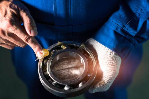
Periodic Maintenance
One of the important notes when using bearings is periodic maintenance. Maintenance will help increase efficiency during operation and also contribute to ensuring the product’s longevity. To maintain bearings, you must choose the right lubricant.
If you don’t have much experience in this area, go to a trusted mechanic. They will help you know which lubricant is suitable for the wheel used.
Know the signs in case of wheel bearing malfunction
Identify the symptoms of a bad bearing for quick repair to avoid serious risks. Bearing failure occurs when the operation is beyond overload or external force… Bearings that are about to be damaged often show the following signs. These signs may not be obvious, so you must be very attentive:
- The car makes noise
- The engine temperature has risen abnormally
- Strange noise
- High vibrations
- Uneven tire wear.
Choose the right car wheel bearing.
There are many types of bearings manufactured to fit each car. Each type of bearing is usually specified by the manufacturer on technical parameters like size, speed, capacity… If you understand the bearing parameters, you can compare them with your car’s operating system to choose the most suitable bearings. But if you are not a professional in the field, do not hesitate to ask for expert opinions or manufacturer recommendations. Additionally, you should choose original bearings to make your car more stable.
Conclusion
Cars are one of our important partners. Take good care of our car. So spend a little time taking care of your car and understanding its components more deeply. We hope the article provides you with useful information.