P064B PTO Control Module

What does it mean?


This is a generic diagnostic trouble code (DTC) and applies to many OBD-II vehicles (1996-newer). This may include, but is not limited to, vehicles from Chrysler, Ford, General Motors, Mercedes-Benz, Toyota, etc. Although generic, the exact repair steps may vary depending on the year, make, model, and powertrain configuration.

A stored P064B code means that the Powertrain Control Module (PCM) has detected a malfunction in the Power Take-Off (PTO) control module.

The PTO control module is responsible for initiating various PTO functions. These may include activating specified lighting, increasing engine speed (when the PTO is engaged), as well as disengaging the drive wheels (using the transfer case). In most cases, the PTO controller is integrated into the PCM, but it can also be a standalone module.

The power take-off is a function included on many hydraulically-operated service vehicles such as tow trucks and dump trucks. It allows a large hydraulic pump to be driven using engine power. With the vehicle stationary and the engine idling, a transfer case on the transmission output shaft allows the drive wheels to be disengaged and the pump to be engaged via an auxiliary drive shaft. This system is quite durable and provides abundant power for heavy functions such as lifting another vehicle (wrecker) or dumping heavy materials (dump truck). There are many specialized applications that use a power take-off system in addition to tow trucks and dump trucks.

Whenever the ignition is turned on and the PCM is powered, several controller self-tests are performed. By performing controller self-tests, the PCM can monitor serial data transmitted on the Controller Area Network (CAN) to ensure that the onboard controllers interface correctly.

If a problem is detected while monitoring the PTO control module, a P064B code will be stored and a Malfunction Indicator Lamp (MIL) may illuminate.

Code P064B
How severe is this DTC?

For safety reasons, power take-off control module codes should be taken seriously. A stored P064B code can result in a lack of PTO function and may pose serious safety risks.

What are some of the symptoms of the code?

Symptoms of a P064B trouble code may include:

  • Inoperative power take-off
  • Slow and labored engine cranking
  • Engine locking up during starting
  • Engine driveability issues
  • Other stored codes

What are some common causes of the code?

Causes of this code may include:

  • Faulty power take-off controller or PCM
  • Open module control voltage supply circuit
  • PCM programming error
  • Open or shorted control circuit

What are the troubleshooting steps for P064B?

A diagnostic scanner, a digital volt/ohmmeter (DVOM), and a reliable source of vehicle information will be needed to diagnose a P064B code.

Consult your vehicle information source for Technical Service Bulletins (TSBs) that match the stored code, the vehicle (year, make, model, and engine), and the symptoms presented. If you find the relevant TSB, it may provide helpful diagnostic information.

Start by connecting the scanner to the vehicle’s diagnostic port and retrieving all stored codes and freeze frame data. You will want to note this information, in case the code proves to be intermittent. After recording all relevant information, clear the codes and test the vehicle (if possible) until the code resets or the PCM enters readiness mode.

If the PCM enters readiness mode, the code is intermittent and will be more difficult to diagnose. The condition that caused the P064B to be stored may need to worsen before an accurate diagnosis can be made. If the code resets, continue your diagnosis.

Use your vehicle information source to obtain connector face views, connector pinout diagrams, component locators, wiring schematics, and diagnostic flowcharts related to the code and the specific vehicle.

Check for battery voltage on the PTO control circuit using the appropriate wiring schematic and your DVOM. If not, check the system fuses and relays and replace faulty parts as needed.

If there is no voltage (and/or ground) on the PTO control circuit (and all fuses and relays appear to be functioning correctly), an inspection of the wiring and harnesses related to the controller is necessary. You will also want to check the chassis and engine ground junctions. Use your vehicle information source to obtain ground locations for the related circuits.

If there is voltage (and ground) on the PTO control circuit, inspect the system controllers for signs of water, heat, or collision damage. Any damaged controller (especially by water) should be considered faulty.

If the controller’s power and ground circuits are intact, suspect a faulty controller or a controller programming error. Replacing the controller will require reprogramming.

Test the integrity of the controller ground by connecting the DVOM’s negative test lead to ground and the positive lead to battery voltage.

P064C Glow Plug Control Module


What Does Code P064C Mean?

The diagnostic code P064C is a generic OBD-II code applicable to many vehicles produced from 1996 onwards. It can involve various manufacturers such as Chrysler, Ford, General Motors, Mercedes-Benz, Nissan, Toyota, and many others. Although generic, the repair steps may vary depending on the year, make, model, and engine configuration.

A P064C code indicates that the Powertrain Control Module (PCM) has detected a problem with the glow plug control module. The latter controls the timing and activation of the glow plugs, which are essential in diesel engines to facilitate starting.

The glow plug control module can be independent or integrated into the PCM. When powered on, the PCM performs self-tests to check the operation of various modules using the communication network (CAN). If a problem is detected, the P064C code is stored and the Malfunction Indicator Lamp (MIL) may illuminate.


Severity of Code P064C

Code P064C is considered serious. A malfunction of the glow plugs can prevent the engine from starting, especially in cold weather.


Symptoms of Code P064C

Here are the most common symptoms associated with this code:

  • Faulty glow plugs;
  • Difficulty or delay in starting, especially in cold weather;
  • Engine stalling during startup;
  • Engine performance issues;
  • Appearance of other diagnostic codes.

Possible Causes

Potential causes of code P064C include:

  • Faulty glow plug controller or PCM;
  • Damaged power supply circuit of the control module;
  • PCM programming error;
  • Open or short circuit in the glow plug circuit.

Diagnostic and Troubleshooting Steps

To diagnose code P064C, you will need a diagnostic scanner, a digital voltmeter/ohmmeter (DVOM), and reliable technical documentation for the vehicle.

  1. Check for Technical Service Bulletins (TSBs)
    Consult relevant TSBs for vehicle-specific information related to the code.

  2. Scan the Vehicle
    Retrieve stored codes and freeze frame data. Clear the codes, then test the vehicle to see if the problem persists. If the code does not return immediately, it may be intermittent.

  3. Check Power Circuits
    Using the electrical diagram, check the battery voltage on the glow plug control circuit. If there is no voltage, inspect fuses, relays, and replace faulty components if necessary.

  4. Inspect Wiring and Connections
    Examine cable harnesses and ground connections. Ensure there are no breaks, short circuits, or corrosion.

  5. Inspect the Control Module
    Look for signs of damage (water, heat, impact). Any module showing such signs will need to be replaced.

  6. Check Ground Circuits
    Test the integrity of ground connections using the DVOM.

  7. Reprogram or Replace the Faulty Module
    If the circuits are in good condition, suspect a faulty control module or a programming error. Any replacement will require proper reprogramming.

By following these methodical steps, you can effectively diagnose and repair a P064C code.

P064D Internal Control Module O2 Sensor Performance Processor Bank 1

What does it mean?

This is a generic diagnostic trouble code (DTC) for the powertrain and generally applies to OBD-II vehicles. This may include, but is not limited to, vehicles from Ford, Mazda, Smart, Land Rover, Dodge, Ram, etc. Although generic, the exact repair steps may vary depending on the year, make, model, and powertrain configuration.

When a P064D code is stored, it means that the Powertrain Control Module (PCM) has detected an internal processor performance error with the Heated Oxygen Sensor (HO2S) circuit for engine bank one. Other controllers may also detect an internal PCM performance error (with the HO2S circuit for bank one) and result in the storage of a P064D.

Bank 1 refers to the engine bank that contains cylinder number one.

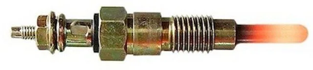
The HO2S is composed of a zirconium dioxide sensing element and a tiny sampling chamber enclosed in a vented steel housing. The sensing element is connected to the conductor wires of the HO2S wiring harness with small platinum electrodes. The HO2S wiring harness is connected to the engine control harness, which provides the PCM with data regarding the percentage of oxygen in the engine’s exhaust gases compared to the oxygen content of the ambient air.

The upstream HO2S is located in the exhaust pipe (between the exhaust manifold and the catalytic converter). The most common method for this is to insert the sensor directly into a threaded boss that is welded into the exhaust pipe. The threaded boss is placed in the downpipe at the most convenient position and angle for sensor access and optimal functionality. Removal and installation of threaded oxygen sensors will require specially designed wrenches or sockets, depending on the vehicle application. The HO2S may also be secured using threaded studs (and nuts) welded to the exhaust pipe.

Exhaust gases are pushed through the exhaust manifold and into the downpipe where they pass over the upstream HO2S. The exhaust gases flow through specially designed vent holes in the HO2S steel housing and through the sensing element. Ambient air is drawn into a small sampling chamber at the center of the sensor, through openings in the conductor wires. In this chamber, the air is heated, forcing ions to produce a voltage (energy). Variations between the concentration of oxygen molecules in the exhaust gases and the ambient air (drawn into the HO2S) create fluctuations in the oxygen ion concentration (inside the sensor). These fluctuations cause the oxygen ions (inside the HO2S) to bounce (rapidly and repeatedly) from one platinum layer to the other. As the oxygen ions move between the platinum layers, it causes voltage changes. These voltage changes are recognized by the PCM as variations in exhaust oxygen concentration and reflect whether the engine is running lean (too little fuel) or rich (too much fuel). When more oxygen is present in the exhaust (lean condition), the voltage signal emitted by the HO2S is lower. When less oxygen is present in the exhaust (rich condition), the voltage signal output is higher. This data is used by the PCM to calculate, among other things, the fuel delivery strategy and ignition timing.

The upstream HO2S typically oscillates between 100 and 900 millivolts (0.1 and 0.9 volts), when the engine is idling and the PCM is operating in closed loop. In closed loop operation, the PCM considers the input signals from the upstream HO2S sensors to regulate the fuel injector pulse width and (ultimately) the fuel delivery. When the engine switches to open loop mode (under cold start and wide-open throttle conditions), the fuel delivery strategy is pre-programmed.

The internal control module monitoring processors are responsible for various controller self-test tasks and the overall responsibility of the internal control module. The HO2S input and output signals are subjected to self-test and are continuously monitored by the PCM and other associated controllers. The Transmission Control Module (TCM), the Traction Control System Module (TCSM), and other controllers also interact with the HO2S.

Whenever the ignition is turned on and the PCM is powered up, the HO2S self-tests are initiated. In addition to running internal controller self-tests, the Controller Area Network (CAN) also compares the signals from each individual module to ensure that each controller is functioning correctly. These tests are performed simultaneously.

If the PCM detects an internal anomaly in the HO2S functionality, a P064D code will be stored and a Malfunction Indicator Lamp (MIL) may be illuminated. Additionally, if the PCM detects a problem between any of the onboard controllers, which would indicate an internal HO2S error, a P064D code will be stored and a Malfunction Indicator Lamp (MIL) may be illuminated. Multiple failure cycles may be required for the MIL to illuminate, depending on the perceived severity of the malfunction.

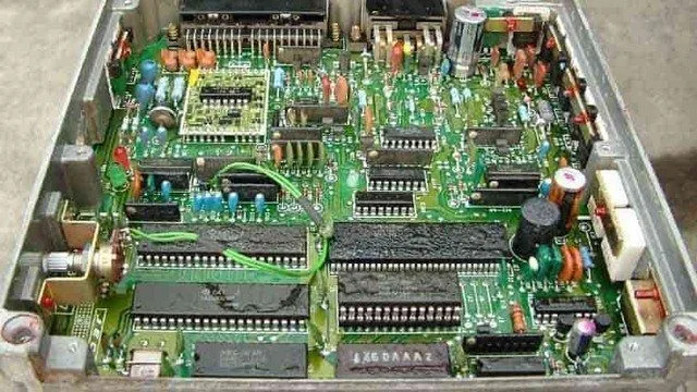
Photo of a PCM with the cover removed:


Powertrain Control Module PCM
How severe is this DTC?

Internal Control Module Processor codes should be classified as severe.

A stored P064D code could lead to a variety of driving issues, including decreased fuel efficiency.
What are some of the symptoms of the code?

Symptoms of a P064D fault code may include:

Reduced fuel efficiency
A general lack of engine performance
A variety of engine driving symptoms
Other stored diagnostic trouble codes

What are some of the common causes of the code?

Causes

of this P064D DTC code may include:

Faulty controller or controller programming error
Faulty HO2S
Rich or lean exhaust conditions
Burned, chafed, broken, or disconnected wiring and/or connectors
Engine exhaust leaks
A faulty controller power relay or blown fuse
Open or shorted circuit or connectors in the CAN harness
Insufficient control module ground

What are the P064D troubleshooting steps?

Even for the most experienced and well-equipped professional technician, diagnosing a P064D code can be very challenging. There is also the issue of reprogramming. Without the necessary reprogramming equipment, it will be impossible to replace a faulty controller and perform a successful repair.

If ECM/PCM power codes are present, they will obviously need to be corrected before attempting to diagnose a P064D.

There are several preliminary tests that can be performed before declaring a controller faulty. A diagnostic scanner, a digital volt/ohmmeter (DVOM), and a reliable source of vehicle information will be necessary.

Connect the scanner to the vehicle’s diagnostic port and retrieve all stored codes and freeze frame data. You will want to note this information, just in case the code proves to be intermittent. After recording all relevant information, clear the codes and test-drive the vehicle until the code resets or the PCM enters readiness mode. If the PCM enters readiness mode, the code is intermittent and will be more difficult to diagnose. The condition that caused the P064D to be stored may even need to worsen before a diagnosis can be made. If the code resets, continue with this short list of preliminary tests.

When trying to diagnose a P064D, information can be your best tool. Search your vehicle information source for Technical Service Bulletins (TSBs) that parallel the stored code, the vehicle (year, make, model, and engine), and the symptoms presented. If you find the right TSB, it can provide diagnostic information that will assist you significantly.

Use your vehicle information source to obtain connector face views, connector pinout diagrams, component locators, wiring schematics, and diagnostic flowcharts related to the code and the specific vehicle.

Use the DVOM to test the controller power fuses and relays. Test and replace blown fuses as needed. Fuses should be tested with the circuit loaded.

If all fuses and relays appear to be functioning as expected, a visual inspection of the wiring and harnesses related to the controller is necessary. You will also want to check the chassis and engine ground junctions. Use your vehicle information source to obtain ground locations for the related circuits. Use the DVOM to test ground integrity.

Visually inspect the system controllers for signs of water, heat, or collision damage. Any damaged controller, especially by water, should be considered faulty.

If the controller power and ground circuits are intact, suspect a faulty controller or a controller programming error. Replacing the controller will require reprogramming. In some cases, you can purchase pre-programmed controllers through aftermarket sources. Other vehicles/controllers will require onboard reprogramming that can only be performed by a dealership or another qualified source.
HO2S Test

Ensure the engine is running efficiently before attempting to diagnose the HO2S. Misfire codes, throttle position sensor codes, manifold air pressure code, and mass air flow sensor codes should be addressed before attempting to diagnose HO2S or lean/rich exhaust codes.

Some automobile manufacturers use a fused circuit to supply voltage to the HO2S system. Test these fuses using the DVOM.

If all fuses are in good working order, locate the HO2S for engine bank one. The vehicle will need to be raised on an appropriate hoist or lifted and secured on safety stands. Once you have accessed the sensor in question, disconnect the harness connector and turn the ignition key to the ON position. You are looking for battery voltage at the HO2S connector. Use the wiring schematic to determine the circuit used to supply battery voltage. Also check the system ground at this point.

If HO2S voltage and ground are present, reconnect the HO2S. Start the engine and test-drive the vehicle. After a test drive, let the engine idle (with the transmission in neutral or park). Use the scanner to observe the HO2S input data. Limit the data stream scope to include only relevant data, and you will get a faster data response. Assuming the engine is running efficiently, the upstream HO2S should switch from rich to lean (and vice versa) regularly with the PCM in closed loop.

Unlike most other codes, P064D is likely caused by a faulty controller or a controller programming error
Test the system ground integrity by connecting the DVOM’s negative test lead to ground and the positive test lead to battery voltage

Internal Control Module O2 Sensor Performance Processor Bank 2

What does it mean?

This is a generic diagnostic trouble code (DTC) for the powertrain and generally applies to OBD-II vehicles. This may include, but is not limited to, vehicles from Ford, Mazda, Smart, Land Rover, Dodge, Ram, etc. Although generic, the exact repair steps may vary depending on the year, make, model, and powertrain configuration.

When a P064E code is stored, it means that the Powertrain Control Module (PCM) has detected an internal processor performance error related to the Heated Oxygen Sensor (HO2S) circuit for engine bank two. Other controllers may also detect an internal PCM performance error (related to the HO2S circuit for bank one) and result in the storage of a P064E code.

Bank 2 refers to the engine bank that does not contain cylinder number 1.

The HO2S consists of a zirconium dioxide sensing element and a tiny sampling chamber enclosed in a vented steel housing. The sensing element is connected to the conductor wires of the HO2S wiring harness with small platinum electrodes. The HO2S wiring harness is connected to the engine control harness, which provides the PCM with data regarding the percentage of oxygen in the engine’s exhaust gases compared to the oxygen content in the ambient air.

The upstream HO2S is located in the exhaust pipe (between the exhaust manifold and the catalytic converter). The most common method for this is to insert the sensor directly into a threaded boss that is welded into the exhaust pipe. The threaded boss is placed in the downpipe at the most convenient position and angle for sensor access and optimal functionality. Removal and installation of threaded oxygen sensors will require specially designed wrenches or sockets, depending on the vehicle application. The HO2S may also be secured using threaded studs (and nuts) welded to the exhaust pipe.

Exhaust gases are pushed through the exhaust manifold and into the downpipe where they pass over the upstream HO2S. The exhaust gases flow through specially designed vent holes in the HO2S steel housing and through the sensing element. Ambient air is drawn into a small sampling chamber in the center of the sensor, through openings in the conductor wires. In this chamber, the air is heated, forcing ions to produce a voltage (energy). Variations between the concentration of oxygen molecules in the exhaust gases and the ambient air (drawn into the HO2S) create fluctuations in the oxygen ion concentration (inside the sensor). These fluctuations cause the oxygen ions (inside the HO2S) to bounce (rapidly and repeatedly) from one platinum layer to the other. As the oxygen ions move between the platinum layers, it causes voltage changes. These voltage changes are recognized by the PCM as variations in exhaust oxygen concentration and reflect whether the engine is running lean (too little fuel) or rich (too much fuel). When more oxygen is present in the exhaust (lean condition), the voltage signal output by the HO2S is lower. When less oxygen is present in the exhaust (rich condition), the voltage signal output is higher. This data is used by the PCM to calculate, among other things, fuel delivery strategy and ignition timing.

The upstream HO2S typically oscillates between 100 and 900 millivolts (0.1 and 0.9 volts) when the engine is idling and the PCM is operating in closed loop. In closed-loop operation, the PCM considers input signals from the upstream HO2S sensors to regulate the fuel injector pulse width and (ultimately) fuel delivery. When the engine enters open-loop mode (during cold start and wide-open throttle conditions), the fuel delivery strategy is pre-programmed.

The internal control module monitoring processors are responsible for various controller self-test tasks and the overall responsibility of the internal control module. HO2S input and output signals are subjected to self-test and are continuously monitored by the PCM and other associated controllers. The Transmission Control Module (TCM), Traction Control System Module (TCSM), and other controllers also interact with the HO2S.

Whenever the ignition is turned on and the PCM is powered up, HO2S self-tests are initiated. In addition to running internal controller self-tests, the Controller Area Network (CAN) also compares the signals from each individual module to ensure each controller is functioning correctly. These tests are performed simultaneously.

If the PCM detects an internal anomaly in HO2S functionality, a P064E code will be stored, and a Malfunction Indicator Lamp (MIL) may be illuminated. Furthermore, if the PCM detects a problem between any of the onboard controllers that would indicate an internal HO2S error, a P064E code will be stored, and a Malfunction Indicator Lamp (MIL) may be illuminated. Multiple failure cycles may be required for MIL illumination, depending on the perceived severity of the malfunction.

Photo of a PCM with the cover removed

:
Powertrain Control Module PCM
How severe is this DTC?

Internal Control Module Processor codes should be classified as severe.

A stored P064E code could lead to various driving issues, including decreased fuel efficiency.
What are some of the symptoms of the code?

Symptoms of a P064E fault code may include:

Reduced fuel efficiency
A general lack of engine performance
A variety of engine driving symptoms
Other stored diagnostic trouble codes

What are some common causes of the code?

Causes

of this P064E DTC code may include:

Faulty controller or controller programming error
Faulty HO2S
Rich or lean exhaust conditions
Burned, chafed, broken, or disconnected wiring and/or connectors
Engine exhaust leaks
A faulty controller power relay or blown fuse
Open or shorted circuit or connectors in the CAN harness
Insufficient control module ground

What are the P064E troubleshooting steps?

Even for the most experienced and well-equipped professional technician, diagnosing a P064E code can be very challenging. There is also the issue of reprogramming. Without the necessary reprogramming equipment, it will be impossible to replace a faulty controller and perform a successful repair.

If ECM/PCM power codes are present, they will obviously need to be rectified before attempting to diagnose a P064E.

There are several preliminary tests that can be performed before declaring a controller faulty. A diagnostic scanner, a digital volt/ohmmeter (DVOM), and a reliable source of vehicle information will be necessary.

Connect the scanner to the vehicle’s diagnostic port and retrieve all stored codes and freeze frame data. You will want to note this information, just in case the code proves to be intermittent. After recording all relevant information, clear the codes and test-drive the vehicle until the code resets or the PCM enters readiness mode. If the PCM enters readiness mode, the code is intermittent and will be more difficult to diagnose. The condition that caused the P064E to be stored may even need to worsen before a diagnosis can be made. If the code resets, continue with this short list of preliminary tests.

When trying to diagnose a P064E, information can be your best tool. Search your vehicle information source for Technical Service Bulletins (TSBs) that parallel the stored code, the vehicle (year, make, model, and engine), and the symptoms presented. If you find the right TSB, it can provide diagnostic information that will assist you significantly.

Use your vehicle information source to obtain connector face views, connector pinout diagrams, component locators, wiring schematics, and diagnostic flowcharts related to the code and the specific vehicle.

Use the DVOM to test the controller power fuses and relays. Test and replace blown fuses as needed. Fuses should be tested with the circuit loaded.

If all fuses and relays appear to be functioning as expected, a visual inspection of the wiring and harnesses related to the controller is warranted. You will also want to check the chassis and engine ground junctions. Use your vehicle information source to obtain ground locations for the related circuits. Use the DVOM to test ground integrity.

Visually inspect the system controllers for signs of water, heat, or collision damage. Any damaged controller, especially by water, should be considered faulty.

If the controller power and ground circuits are intact, suspect a faulty controller or a controller programming error. Replacing the controller will require reprogramming. In some cases, you can purchase pre-programmed controllers through aftermarket sources. Other vehicles/controllers will require onboard reprogramming that can only be performed by a dealership or another qualified source.
HO2S Test

Ensure the engine is running efficiently before attempting to diagnose the HO2S. Misfire codes, throttle position sensor codes, manifold air pressure codes, and mass air flow sensor codes should be addressed before attempting to diagnose HO2S or lean/rich exhaust codes.

Some automobile manufacturers use a fused circuit to supply voltage to the HO2S system. Test these fuses using the DVOM.

If all fuses are in good working order, locate the HO2S for engine bank one. The vehicle will need to be raised on an appropriate hoist or lifted and secured on safety stands. Once you have accessed the sensor in question, disconnect the harness connector and turn the ignition key to the ON position. You are looking for battery voltage at the HO2S connector. Use the wiring schematic to determine the circuit used to supply battery voltage. Also check the system ground at this point.

If HO2S voltage and ground are present, reconnect the HO2S. Start the engine and test-drive the vehicle. After a test drive, let the engine idle (with the transmission in neutral or park). Use the scanner to observe the HO2S input data. Limit the data stream scope to include only relevant data, and you will get a faster data response. Assuming the engine is running efficiently, the upstream HO2S should regularly switch from rich to lean (and vice versa) with the PCM in closed loop.

Unlike most other codes, P064E is likely caused by a faulty controller or a controller programming error
Test the system ground integrity by connecting the DVOM’s negative test lead to ground and the positive test lead to battery voltage

P064F Unauthorized software / calibration detected

What Does It Mean?

This is a generic diagnostic trouble code (DTC) and applies to many OBD-II vehicles (1996-newer). This may include, but is not limited to, Acura, Audi, Buick, Cadillac, Chevrolet, Chrysler, Ford, Hyundai, Jaguar, Kia, Nissan, Scion, Toyota vehicles, etc. Although generic, the exact repair steps may vary depending on the year, make, model, and powertrain configuration.

A stored code P064F means that the Powertrain Control Module (PCM) has detected an unauthorized or unrecognized software application or a controller calibration error.

Installing factory software and calibrating onboard controllers is often referred to as programming. While most programming is done before the vehicle is delivered to the owner, the onboard controllers continue to adapt to specific circumstances and learn effectively to meet the needs of individual drivers and geographic locations (among others). Factors including voltage spikes, excessive temperatures, and excessive humidity can contribute to software and calibration failure.

Installing aftermarket software may result in a P064F code being stored, but it is usually temporary. Once the PCM has learned the software and the code is cleared, it typically does not reset.

Whenever the ignition is turned on and the PCM is powered, several controller self-tests are performed. By performing controller self-tests, the PCM can monitor serial data that is carried on the Controller Area Network (CAN) to ensure that the onboard controllers interface correctly. Memory functions, as well as software applications, are tested at this time and also tested periodically when the ignition is in the ON position.

If a problem is detected in the monitoring controller’s software/calibration, a P064F code will be stored and a Malfunction Indicator Lamp (MIL) may be illuminated.

A typical Powertrain Control Module PCM, opened:


Powertrain Control Module P064F
How Severe Is This DTC?

A P064F should be considered severe as it can lead to various engine starting and/or driving problems.
What are some of the symptoms of the code?

Symptoms of a P064F trouble code may include:

Engine crank no start or delayed start
Engine driveability issues
Other stored codes

What are some of the common causes of the code?

Causes

of this code may include:

PCM programming error
Faulty controller or PCM
Installation of aftermarket or high-performance software

What are the P064F troubleshooting steps?

Even for the most experienced and well-equipped technician, a P064F code can be particularly difficult to diagnose. Without access to reprogramming equipment, an accurate diagnosis will be virtually impossible.

Consult your vehicle’s information source for Technical Service Bulletins (TSBs) that reproduce the stored code, the vehicle (year, make, model, and engine), and the symptoms presented. If you find the appropriate TSB, it may provide helpful diagnostic information.

Start by connecting the scanner to the vehicle’s diagnostic port and retrieving all stored codes and freeze frame data. You will want to note this information, just in case the code proves to be intermittent.

After recording all relevant information, clear the codes and test drive the vehicle (if possible) until the code resets or the PCM enters readiness mode.

If the PCM enters readiness mode, the code is intermittent and will be even more difficult to diagnose. The condition that caused the P064F to be stored may need to worsen before an accurate diagnosis can be reached. On the other hand, if the code does not reset and no driveability symptoms manifest, the vehicle may be operating normally.

Test the controller ground integrity by connecting the DVOM’s negative test lead to ground and the positive test lead to battery voltage

Malfunction Indicator Lamp (MIL) Control Circuit

Code P0650: Malfunction Indicator Lamp (MIL) Problem – Causes, Symptoms, and Solutions

1. What is Code P0650?

Code P0650 is a generic OBD-II code related to the powertrain. It applies to all OBD-II compliant vehicles (1996 and newer), although repair procedures may vary slightly by make and model.

This code is defined when the Powertrain Control Module (PCM) detects a problem in the Malfunction Indicator Lamp (MIL) circuit. This lamp, also known as the “Check Engine” or “Service Engine Soon” light, normally illuminates when there is a malfunction in the engine or another vehicle system.

How does the MIL work?

  • When you turn the ignition on, the MIL light comes on for a few seconds, then turns off if no problem is detected.
  • If the PCM detects an anomaly in the MIL circuit, it stores the P0650 code.

2. Symptoms of Code P0650

A malfunctioning MIL can cause the following symptoms:

🚨 The MIL does not illuminate when it should be activated.
🚨 The MIL stays on permanently, even without an engine problem.
🚨 Difficulty diagnosing other problems, because the MIL is not working correctly.


3. Possible Causes of Code P0650

Several elements can be responsible for the MIL malfunction:

🔹 Blown MIL bulb or LED
🔹 Faulty wiring harness (short circuit or open circuit)
🔹 Poor connection between the bulb, the dashboard, and the PCM
🔹 Blown PCM or MIL fuse
🔹 Faulty PCM (Powertrain Control Module) (rare, but possible)


4. Diagnosis and Possible Solutions

Step 1: Check Normal MIL Operation

  1. Turn the ignition on without starting the engine.
  2. Check if the MIL illuminates for a few seconds before turning off.
    • If yes → The bulb/LED is working correctly.
    • If no → Proceed to the next step.

Step 2: Test the MIL Bulb or LED

  1. Remove the dashboard and access the MIL bulb.
  2. Check if the bulb is blown and replace it if necessary.
  3. Ensure the bulb is properly seated and connected correctly.

Step 3: Inspect the MIL Wiring

  1. Examine the wiring harness between the MIL and the PCM.
  2. Check for any cut, damaged wires, or loose connections.
  3. Inspect the connectors for corrosion, bent, or broken pins.

Step 4: Check the Instrument Cluster

  1. Check if the other dashboard indicators (temperature, oil pressure, fuel gauge, etc.) are working correctly.
  2. If multiple indicators are faulty, there might be a problem with the dashboard itself.

Step 5: Check the PCM or MIL Fuse

  1. Consult your vehicle’s manual to locate the PCM or MIL fuse.
  2. Check if it is blown and replace it if necessary.

Step 6: Test the Circuit with a Multimeter (DVOM)

  1. Use a digital multimeter to test the voltage on the wires between the MIL and the PCM.
  2. Check for a short to ground or an open circuit.

Step 7: Check and Replace the PCM (Last Resort)

If all other checks are correct and the problem persists, the PCM might be the cause. However, replacing the PCM requires reprogramming with specialized equipment. Consult a qualified technician before considering this option.


5. Conclusion

Code P0650 indicates a problem with the Malfunction Indicator Lamp (MIL), which can be caused by a simple blown bulb or a more complex issue in the electrical circuit. A good diagnosis involves:

✅ Checking the bulb and dashboard
✅ Inspecting the cables and connectors
✅ Checking the fuses and electrical circuit

If the problem is not identified after these steps, more advanced intervention on the PCM may be necessary. 🚗💡

Code P0651: Causes, Symptoms and Solutions – Complete Guide

What is Code P0651?

The diagnostic code P0651 is a generic OBD-II code that applies to vehicles equipped with an electronic engine management system. This code indicates that the Powertrain Control Module (PCM) has detected an open circuit on the reference voltage line “B”. An open circuit can be interpreted as a lack of connection or a break in the signal.

The sensor in question is typically related to components such as the automatic transmission, transfer case, or one of the differentials. Code P0651 is often accompanied by another, more specific sensor code that should be diagnosed first.


Symptoms of Code P0651

The severity of symptoms depends on the affected circuit. The most common issues include:

  • 🚨 Check Engine Light (MIL) on
  • ⚠️ Transmission malfunction (unpredictable, delayed, or absent gear shifts)
  • 🔄 Difficulty switching to sport or economy mode
  • 🔧 Transfer case problems (inability to shift gears or engage the differential)
  • 📉 Erratic or non-functional gauges (odometer, speedometer)

Possible Causes of P0651

Code P0651 can be caused by several factors, including:

  1. Electrical issues:
    • Open circuit in the reference voltage line “B”
    • Damaged or corroded connectors
    • Blown fuses or faulty fuse links
    • Failed system power relay
  2. Sensor failures:
    • Faulty transmission sensor, speed sensor, or other sensor
  3. PCM problem:
    • Programming error
    • Malfunctioning engine control module

Diagnostic and Repair Procedures

1. Scan Error Codes

  • Use an OBD-II diagnostic tool to retrieve associated error codes.
  • Note any additional codes that may guide the diagnosis.
  • Clear the codes and perform a test drive to see if they return immediately.

2. Check Fuses and Electrical Power

  • Inspect all fuses related to the engine management system.
  • Check the reference voltage at the relevant sensor (typically 5V).
  • Replace blown fuses and inspect wiring for short circuits.

3. Test Sensors

  • Test the resistance and continuity of the affected sensors with a multimeter.
  • Compare the obtained values to the manufacturer’s specifications.
  • Replace any faulty sensor.

4. Inspect Connections and Wiring

  • Perform a visual inspection of connectors and cable harnesses.
  • Look for cut, burned, or oxidized wires.
  • Repair or replace damaged components.

5. Test the PCM

  • If all previous steps are satisfactory and the code persists, a PCM error may be the cause.
  • Perform a PCM reset and reprogram it if necessary.
  • As a last resort, replace the PCM.

Conclusion

The code P0651 is often an indicator of an open circuit issue affecting a key sensor in the transmission or engine management system. A methodical approach is essential:

  • Start with a comprehensive OBD-II diagnosis.
  • Check fuses, wiring, and connectors.
  • Test sensors and reference voltage.
  • Inspect the PCM if necessary.

Once the problem is identified and fixed, clear the code and perform a test drive to confirm the repair. If in doubt, a professional can help diagnose the issue more accurately.

Need more information on OBD-II codes? Check out our guides on P0650, P0652, and P0700 codes to deepen your diagnosis!

P0652 Low Sensor B Reference Voltage Circuit

What does it mean?

This diagnostic trouble code (DTC) is a generic powertrain code, meaning it applies to OBD-II equipped vehicles. Although generic, specific repair steps may vary by make/model.

If your OBD II equipped vehicle has a stored P0652, it means the Powertrain Control Module (PCM) has detected a low reference voltage signal for a specific sensor designated as “B”. The sensor in question is typically associated with the automatic transmission, transfer case, or one of the differentials.

A more specific sensor code will almost always accompany this code. P0652 adds that the sensor reference circuit voltage is low. To determine the location (and function) of the sensor regarding the vehicle in question, consult a reliable vehicle information source (All Data DIY is an excellent source). You might suspect a PCM programming error if P0652 is stored alone. You’ll need to diagnose and repair any other sensor codes before diagnosing and repairing P0652 – but keep in mind the low reference voltage condition.

The sensor in question receives reference voltage (typically five volts) through a switched circuit (powered with the key on). There will also be a ground signal. The sensor will be of variable resistance or electromagnetic type and will complete the circuit. The sensor’s resistance should decrease as pressure, temperature, or speed increases and vice versa. When the sensor resistance changes (under varying conditions), it provides the PCM with an input voltage signal.

If the input voltage signal received by the PCM is below a programmed threshold, a P0652 will be stored. A Malfunction Indicator Lamp (MIL) may also illuminate. Some vehicles require multiple drive cycles (with a failure) for the MIL to illuminate. Allow the PCM to enter readiness mode before considering a repair successful. Simply clear the code once repairs are made and drive the vehicle normally. If the PCM enters readiness mode, the repair was successful. If the code resets, the PCM won’t enter readiness mode and you know a malfunction still exists.
Severity and Symptoms

The severity of a stored P0652 depends on which sensor circuit is experiencing the low voltage condition. Other stored codes must be considered before determining severity.

Symptoms of a P0652 code may include:

Transmission failure to switch between sport and economy modes
Transmission shifting malfunctions
Delayed (or no) transmission engagement
Transmission failure to switch between four-wheel drive and two-wheel drive modes
Transfer case failure to shift from low to high range
Lack of front differential engagement
Lack of front hub engagement
Erratic or inoperative speedometer/odometer

Causes

Possible causes of this engine code include:

Faulty sensor
Defective or blown fuses and/or fuse links
Faulty system power relay
Open circuits and/or connectors

Diagnostic and Repair Procedures

A diagnostic scanner, digital volt/ohmmeter (DVOM), and reliable vehicle information source (such as All Data DIY) will be needed to diagnose a stored P0652 code. A portable oscilloscope may also prove useful in your diagnosis.

First, consult your vehicle information source to determine the location and function of the sensor in question regarding your specific vehicle. Perform a visual inspection of wiring harnesses and connectors related to the sensor system. Repair or replace damaged or burned wiring, connectors, and components as needed. Second, connect the scanner to the vehicle’s diagnostic port and retrieve all stored trouble codes and freeze frame data. Document the codes, the order in which they were stored, and any associated freeze frame data, as this information may prove useful if the code proves intermittent. You can now proceed to clear the code; then test drive the vehicle to see if it immediately resets.

If the code immediately resets, use the DVOM to test the reference voltage and ground signals at the sensor in question. You would normally expect to find five volts and ground at the sensor connector.

Continue by testing the sensor’s resistance and continuity levels if voltage and ground signals are present at the sensor connector. Obtain test specifications from your vehicle information source and compare them to your actual results. Sensors not meeting these specifications should be replaced.

Disconnect all associated controllers from system circuits before testing resistance with the DVOM. Failure to do so could result in PCM damage. If reference voltage is low (at the sensor level), use the DVOM to check circuit resistance and continuity between the sensor and PCM. Replace open or shorted circuits as needed. If the sensor in question is electromagnetic with an alternating signal, use the oscilloscope to monitor data. Focus on completely open circuits and issues.

Additional diagnostic notes:

This type of code is typically provided as support for a more specific code
A stored P0652 code is normally associated with the transmission

P0653 Sensor Reference Voltage B Circuit High

OBD-II Diagnostic Code P0653: Definition, Symptoms, Causes, and Repair Procedure


1. Definition of Code P0653

The code P0653 is a generic OBD-II code related to the powertrain, indicating a reference voltage too high on sensor “B” circuit.

  • Function of sensor “B”:
    This sensor is typically associated with automatic transmission, transfer case, or front differential systems, measuring parameters such as pressure, temperature, or speed.
  • Role of the PCM:
    The powertrain control module detects an abnormally high voltage in the reference circuit (usually 5V), disrupting communication with the sensor.

2. Common Symptoms

  • 🚨 Check Engine Light illuminated (MIL).
  • 🛑 Transmission problems:
  • Delayed or absent gear engagement.
  • Malfunction of Sport/Economy or 4×4/2×4 modes.
  • Erratic shifting.
  • 🔄 Transfer case malfunctions:
  • Unable to switch to high or low range.
  • 📏 Erratic or inoperative odometer/speedometer.

3. Possible Causes

Electrical/Mechanical Problems

  1. Short circuit in the sensor circuit:
  • Chafed wires, degraded insulation, or accidental contact with a voltage source.
  1. Faulty sensor “B”:
  • Internal resistance out of specifications or total failure.
  1. PCM programming error:
  • Corrupted software or PCM hardware failure.
  1. Damaged connectors:
  • Corroded, oxidized, or pushed back pins.

4. Diagnostic Procedure

Step 1: Preparation

  • Required tools:
  • OBD-II scanner, digital multimeter (DVOM), portable oscilloscope, technical manual (e.g., AllDataDIY).
  • Initial checks:
  • Consult the manufacturer’s Technical Service Bulletins (TSBs).
  • Diagnose any related codes first (e.g., P0700, P0730).

Step 2: Visual Inspection

  • Wiring and connectors:
  • Look for exposed wires, burns, or signs of corrosion.
  • Check the sensor “B” connector (cleanliness, pin alignment).

Step 3: Analysis with OBD-II Scanner

  • Retrieve codes and freeze frame data:
  • Note the order of codes and recorded parameters.
  • Monitor data stream:
  • Observe the sensor “B” voltage in real time.

Step 4: Electrical Tests

  1. Reference voltage test:
  • Disconnect the sensor and check voltage at the connector (expected: ~5V).
  • A voltage above 5V indicates a short to B+.
  1. Sensor resistance test:
  • Measure resistance between terminals (consult manufacturer specifications).
  1. Continuity and isolation test:
  • Check for absence of short circuits between the sensor circuit and ground/other wires.

Step 5: Using an Oscilloscope

  • Electromagnetic sensors:
  • Analyze the signal for spikes, dips, or a saturated signal.

5. Repair Procedure

  • Replacement of sensor “B”:
  1. Locate the sensor (transmission, transfer case, or differential).
  2. Disconnect the connector and remove the sensor.
  3. Install a new sensor compliant with OEM specifications.
  • Wiring repair:
  • Insulate or replace damaged wires.
  • PCM update:
  • If necessary, reprogram or replace the PCM.

6. Repair Validation

  1. Reset the P0653 code with the scanner.
  2. Perform a road test:
  • Verify proper operation of the transmission and 4×4 modes.
  • Confirm that the Check Engine Light remains off.
  1. Check OBD-II readiness mode:
  • The PCM should enter “ready” mode if the repair is successful.

7. Technical Recommendations

  • 🔧 Priority:
    This code can mask other issues. Address related codes first.
  • ⚠️ Precautions:
  • Always disconnect the PCM before testing resistance to avoid damage.
  • Use original parts to ensure electrical compatibility.
  • 📄 References:
    Consult model-specific wiring diagrams in technical manuals.

Reference Diagram:
Sensor “B” electrical circuit – [Model/Year] (to be included if available).

💡 Tip:

  • An oscilloscope is essential for diagnosing electromagnetic sensors with alternating signals.
  • If the code reappears, suspect an intermittent problem or a failing PCM.

References:
Use databases like AllDataDIY or Mitchell1 for vehicle-specific procedures.

P0654 Engine Speed Output Circuit Malfunction

What does it mean?

This is a generic diagnostic code (DTC) and applies to many OBD-II vehicles (1996-newer). This may include, but is not limited to, vehicles from Buick, Cadillac, Chevrolet, Ford, GMC, Opel, Peugeot, etc. Although generic, the exact repair steps may vary depending on the year, make, model, and powertrain configuration.

A stored code P0654 means that the Powertrain Control Module (PCM), or one of the other associated controllers, has detected an anomaly in the engine speed (RPM) output circuit.

The engine RPM output circuit is responsible for providing an engine RPM output signal to the dashboard tachometer and other controllers. The PCM receives engine speed data from the engine’s camshaft and crankshaft sensors. This data is primarily used to calculate and monitor engine operation and is then transmitted to the tachometer and other controllers (to which it is instrumental).

If a problem is detected while monitoring the engine speed output circuit, a P0654 code will be stored, and a Malfunction Indicator Lamp (MIL) may illuminate.

A tachometer indicating engine speed:

P0654 Engine Tachometer
How severe is this DTC?

A P0654 should be classified as severe because it could lead to transmission shifting issues and/or problems with the Anti-lock Braking System (ABS) and Traction Control System (TCS).
What are some of the symptoms of the code?

Symptoms of a P0654 trouble code may include:

Irregular or harsh transmission shifting
ABS or TCS problems
Engine operation issues
Stored ABS and TCS codes

What are some common causes of the code?

Causes

of this code may include:

PCM programming error
Faulty controller or PCM
Open or shorted circuit between the PCM and the dashboard or other controllers

What are the troubleshooting steps for P0654?

If there are any Vehicle Speed Sensor (VSS) codes, engine speed input codes, camshaft position sensor codes, or crankshaft position sensor codes; diagnose and repair those before attempting to diagnose a stored P0654.

Consult your vehicle’s information source for Technical Service Bulletins (TSB) that match the stored code, the vehicle (year, make, model, and engine), and the symptoms presented. If you find the appropriate TSB, it may provide helpful diagnostic information.

A diagnostic scanner, a digital volt/ohmmeter, and an oscilloscope will be necessary to accurately diagnose a P0654 code. A reliable source of vehicle information will also be required.

Start by connecting the scanner to the vehicle’s diagnostic port and retrieving all stored codes and freeze frame data. You’ll want to note this information, just in case the code proves to be intermittent.

After recording all relevant information, clear the codes and test-drive the vehicle (if possible) until the code resets or the PCM enters readiness mode.

If the PCM enters readiness mode, the code is intermittent and will be even more difficult to diagnose. The condition that caused the P0654 to be stored may need to worsen before an accurate diagnosis can be made. On the other hand, if the code does not reset and no driving symptoms manifest, the vehicle may be operating normally.

If the P0654 is immediately reset, proceed with a visual inspection of the wiring and connectors related to the system. Harnesses that are broken or disconnected should be repaired or replaced as necessary.

If the wiring and connectors appear functional, use your vehicle information source to obtain the appropriate wiring diagrams, connector face views, connector pinout diagrams, and diagnostic flowcharts.

Once you have the correct information, use your DVOM and oscilloscope to test the engine RPM output at the appropriate pin of the PCM connector. If no RPM output signal is found, suspect a faulty PCM or a PCM programming error.

If an engine RPM output signal is found at the PCM connector, test the corresponding circuit (as presented) at the dashboard tachometer. If the tachometer signal is not found, you have an open circuit between the PCM and the dashboard. Repair or replace the circuit and retest.

If a P0654 code is stored and the tachometer is operational, suspect a faulty PCM or a PCM programming error