P0641 Sensor Reference Voltage A Circuit Open

What does it mean?

This diagnostic trouble code (DTC) is a generic powertrain code, meaning it applies to vehicles equipped with OBD-II. Although generic, specific repair steps may vary by make/model.

When I find a stored P0641 code, it means the Powertrain Control Module (PCM) has detected an open circuit for a particular sensor; designated in this case as “A”. When diagnosing an OBD-II code, the term open can be replaced with absent.

The sensor in question is typically associated with the automatic transmission, transfer case, or one of the differentials. This code will almost always be accompanied by a more specific sensor code. The P0641 adds that the circuit is open. Consult a reliable vehicle information source (All Data DIY is a great choice) to determine the location (and function) of the sensor regarding the vehicle in question. If P0641 is stored alone, suspect that a PCM programming error has occurred. Obviously, you will need to diagnose and repair any other sensor codes before diagnosing and repairing the P0641 – but keep the “A” open circuit in mind.

A Reference Voltage

A reference voltage (usually five volts) is applied to the sensor in question via a switched circuit (powered with the key on). There should also be a ground signal. The sensor is likely a variable resistance or electromagnetic type and completes a particular circuit. The sensor’s resistance decreases as pressure, temperature, or speed increases and vice versa. As the sensor’s resistance changes with conditions, it provides the PCM with an input voltage signal. If this input voltage signal is not received by the PCM, the circuit is considered open and a P0641 will be stored.

A Malfunction Indicator Lamp (MIL) may also be illuminated, but keep in mind that some vehicles require multiple drive cycles (with a failure) for an MIL to illuminate. For this reason, you should allow the PCM to enter readiness mode before considering a repair successful. Simply clear the code, once repairs are made, and drive the vehicle normally. If the PCM enters readiness mode, the repair was successful. If the code resets, the PCM will not enter readiness mode and you will know you still have a problem.
Severity and Symptoms

The severity of a stored P0641 depends on which sensor circuit is experiencing an open condition. Other stored codes must be considered before the severity can be determined.

Symptoms of a P0641 code may include:

  • Transmission failure to switch between sport and economy modes
  • Transmission shifting malfunctions
  • Delayed (or no) transmission engagement
  • Transmission failure to switch between four-wheel drive and two-wheel drive modes
  • Transfer case failure to shift from low to high range
  • Lack of front differential engagement
  • Lack of front hub engagement
  • Erratic or inoperative speedometer/odometer

Possible causes of this engine code include:

  • Open circuits and/or connectors
  • Faulty or blown fuses and/or fuse links
  • Faulty system power relay
  • Bad sensor

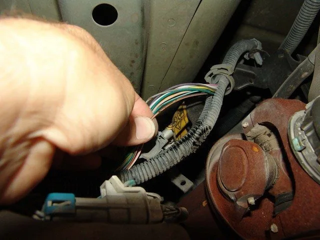
An Example of a P0641 Fault in the Wiring Harness

Diagnostic and Repair Procedures

To diagnose a stored P0641 code, I would need access to a diagnostic scanner, a digital volt/ohmmeter (DVOM), and a reliable vehicle information source (like All Data DIY). A portable oscilloscope can also be helpful in some circumstances.

Use your vehicle information source to determine the location and function of the sensor in question, regarding your specific vehicle. Check system fuses and fuse links with the circuit under full load. Fuses that may seem normal when there is very little load on the circuit often fail when the circuit is fully loaded. Blown fuses should be replaced, keeping in mind that a short circuit is likely the cause of the blown fuse.

Perform a visual inspection of wiring harnesses and connectors related to the sensor system. Repair or replace damaged or burnt wiring, connectors, and components as needed.

Next, I would connect the scanner to the vehicle’s diagnostic connector and retrieve all stored trouble codes. I like to write them down, along with any associated freeze frame data, as this information can prove useful if the code turns out to be intermittent. After that, I would go ahead and clear the code and test drive the vehicle to see if it immediately reset.

If all system fuses are intact and the code immediately resets, use the DVOM to test the reference voltage and ground signals at the sensor in question. Typically, you should expect to find five volts and a common ground at the sensor connector.

If voltage and ground signals are present at the sensor connector, proceed by testing the sensor’s resistance and continuity levels. Use your vehicle information source to obtain test specifications and compare your actual results with them. Sensors that do not meet these specifications should be replaced.

Disconnect all associated controllers from the system circuits before testing resistance with the DVOM. If there is no reference voltage signal at the sensor, disconnect all associated controllers and use the DVOM to check circuit resistance and continuity between the sensor and the PCM. Replace open or shorted circuits as necessary. If an electromagnetic sensor is used, with an alternating signal, use the oscilloscope to monitor live data; paying close attention to glitches and completely open circuits.

Additional Diagnostic Notes:

  • This type of code is usually provided as support for a more specific code
  • A stored P0641 code is normally associated with the transmission

P0642 Sensor Reference Voltage A Circuit Low

What Does It Mean?

This diagnostic trouble code (DTC) is a generic powertrain code, meaning it applies to OBD-II equipped vehicles. Although generic, specific repair steps may vary by make/model.

If your OBD II equipped vehicle has a stored P0642, it means the Powertrain Control Module (PCM) has detected a low reference voltage signal for a particular sensor designated “A”. The sensor in question is typically associated with the automatic transmission, transfer case, or one of the differentials.

A more specific sensor code will almost always accompany this code. P0642 adds that the sensor reference circuit voltage is low. To determine the location (and function) of the sensor regarding the specific vehicle, consult a reliable vehicle information source (All Data DIY is an excellent source). Suspect a PCM programming error if P0642 is stored alone. You’ll need to diagnose and repair any other sensor codes before diagnosing and repairing P0642 – but keep the low reference voltage condition in mind.

The sensor in question receives reference voltage (typically five volts) through a switched circuit (powered with the key on). There will also be a ground signal. The sensor will be of variable resistance or electromagnetic type and will complete the circuit. The sensor’s resistance should decrease as pressure, temperature, or speed increase and vice versa. When the sensor resistance changes (under varying conditions), it provides the PCM with an input voltage signal.

If the input voltage signal received by the PCM is below a programmed threshold, a P0642 will be stored. A Malfunction Indicator Lamp (MIL) may also illuminate. Some vehicles require multiple drive cycles (with a failure) for the MIL to illuminate. Allow the PCM to enter readiness mode before considering a repair successful. Simply clear the code once repairs are made and drive the vehicle normally. If the PCM enters readiness mode, the repair was successful. If the code resets, the PCM will not enter readiness mode, and you know a malfunction still exists.
Severity and Symptoms

The severity of a stored P0642 depends on which sensor circuit is experiencing the low voltage condition. Other stored codes must be considered before determining severity.

Symptoms of a P0642 code may include:

  1. Transmission failure to switch between sport and economy modes
  2. Transmission shifting malfunctions
  3. Delayed (or no) transmission engagement
  4. Transmission failure to switch between four-wheel drive and two-wheel drive modes
  5. Transfer case failure to shift from low to high range
  6. Lack of front differential engagement
  7. Lack of front hub engagement
  8. Erratic or inoperative speedometer/odometer

Possible causes of this engine code include:

  • Faulty sensor
  • Defective or blown fuses and/or fuse links
  • Faulty system power relay
  • Open circuits and/or connectors

Diagnostic and Repair Procedures

A diagnostic scanner, digital volt/ohmmeter (DVOM), and a reliable vehicle information source (such as All Data DIY) will be needed to diagnose a stored P0642 code. A portable oscilloscope may also prove useful in your diagnosis.

First, consult your vehicle information source to determine the location and function of the sensor in question regarding your specific vehicle. Perform a visual inspection of wiring harnesses and connectors related to the sensor system. Repair or replace damaged or burnt wiring, connectors, and components as needed. Second, connect the scanner to the vehicle’s diagnostic port and retrieve all stored trouble codes and freeze frame data. Document the codes, the order in which they were stored, and any associated freeze frame data, as this information may be helpful if the code proves intermittent. You can now proceed to clear the code; then test drive the vehicle to see if it immediately resets.

If the code immediately resets, use the DVOM to test the reference voltage and ground signals at the sensor in question. You would normally expect to find five volts and a ground at the sensor connector.

Continue by testing the sensor’s resistance and continuity levels if voltage and ground signals are present at the sensor connector. Obtain testing specifications from your vehicle information source and compare your actual results to them. Sensors not meeting these specifications should be replaced.

Disconnect all associated controllers from the system circuits before testing resistance with the DVOM. Failure to do so could result in PCM damage. If the reference voltage is low (at the sensor level), use the DVOM to check circuit resistance and continuity between the sensor and the PCM. Replace open or shorted circuits as necessary. If the sensor in question is electromagnetic with an alternating signal, use the oscilloscope to monitor data. Focus on issues and completely open circuits.

Additional Diagnostic Notes:

This type of code is typically provided as support for a more specific code
A stored P0642 code is normally associated with the transmission

P0643 Sensor Reference Voltage A Circuit High

What Does It Mean?

This diagnostic trouble code (DTC) is a generic powertrain code, meaning it applies to OBD-II equipped vehicles. Although generic, specific repair steps may vary by make/model.

When faced with a stored P0643 code, I know from experience that the powertrain control module (PCM) has detected a high reference voltage condition for a specific sensor labeled “A”. I recall that the sensor in question has always been related to automatic transmission, transfer case, or front differential.
An additional sensor code will likely point me in the specific direction of the malfunction, with P0643 adding that the reference voltage for sensor “A” circuit is too high. To determine the location (and function) of the sensor for the specific vehicle, I would consult a reliable vehicle information source like All Data DIY. If P0643 was stored alone, I would suspect a PCM programming error occurred. I always diagnose and repair any other sensor codes before addressing P0643 – keeping in mind the above-normal reference voltage condition – because it will usually disappear once other (more specific) sensor codes are fixed.

I realize the sensor in question is normally powered by a reference voltage signal (typically five volts) through a switched circuit (powered with ignition on) and a ground signal. Experience dictates that the sensor will be either variable resistance or electromagnetic type and will complete the circuit in question. Typically, sensor resistance should decrease as pressure, temperature, or speed increases and vice versa. When the sensor’s resistance level changes (under varying conditions) and the circuit voltage responds; the PCM recognizes voltage variations as changes in pressure, temperature, or speed. If the input voltage signal received by the PCM exceeds a programmed limit, P0643 will be stored and a malfunction indicator light (MIL) may illuminate. Some models require multiple drive cycles (with failure) for MIL illumination. Good things happen when I allow the PCM to enter readiness mode before considering a repair successful. I clear the code once repairs are made and drive the vehicle normally (before returning it to the customer). If the PCM enters readiness mode, the repair succeeded. If the code resets, the PCM won’t enter readiness mode and I know a malfunction still exists.
Severity and Symptoms

The urgency of a stored P0643 depends on which sensor circuit is experiencing the high reference voltage condition. Accompanying codes must be considered before determining severity level.

Symptoms of P0643 code may include:

Delayed (or no) transmission engagement
Transmission failure to switch between sport and economy modes
Transmission shifting malfunctions
Transmission failure to switch between four-wheel drive and two-wheel drive modes
Transfer case failure to shift from low to high range
Lack of front differential engagement
Lack of front hub engagement
Erratic or inoperative speedometer/odometer

Causes

Possible causes of this engine code include:

Shorted circuits and/or connectors
Faulty sensor
PCM programming error or defective PCM

Diagnostic and Repair Procedures

Before starting my diagnosis for P0643, I prefer to have a diagnostic scanner, digital volt/ohmmeter (DVOM), and reliable vehicle information source (like All Data DIY). I’ve also found a portable oscilloscope can be helpful in this diagnosis.

I would begin by consulting my vehicle information source to determine the sensor’s location and function for the specific vehicle. I might continue by performing a visual inspection of wiring harnesses and connectors related to the sensor circuit. I would repair or replace damaged or burned wiring, connectors, and components as needed.

Next, I prefer connecting the scanner to the vehicle’s diagnostic port and retrieving all stored trouble codes and freeze frame data. I record the codes, the order they were stored, and any associated freeze frame data, as this information can prove useful if the code proves intermittent. Now I would proceed to clear the codes and test drive the vehicle to see if it resets.

If the code immediately resets, I would use the DVOM to test reference voltage and ground signals at the sensor in question. I would expect to find five volts and ground at the sensor connector.

I would probably continue by testing sensor resistance levels and continuity if voltage and ground signals are present at the sensor connector. I can obtain specifications from my vehicle information source and compare my actual results with them. Sensors not meeting these specifications will need replacement.

I always disconnect all associated controllers from system circuits before testing resistance with DVOM because I know failure to do so can result in PCM damage. If reference voltage is high (at sensor level), use DVOM to check circuit resistance and continuity between sensor and PCM. Replace shorted circuits as needed.

If the sensor in question is electromagnetic with alternating signal, use the oscilloscope to monitor live data. Focus on spikes, glitches, and maximized circuits.

Additional Diagnostic Notes:

This type of code is usually provided as support for a more specific code
A stored P0643 code is normally associated with transmission

Driver Information Center Serial Communication Circuit

What does it mean?

This is a generic diagnostic trouble code (DTC) and applies to many OBD-II vehicles (1996-newer). This may include, but is not limited to, vehicles from Audi, BMW, General Motors, Ford, Jaguar, Mercedes-Benz, Volkswagen, etc. Although generic, the exact repair steps may vary depending on the year, make, model, and powertrain configuration.

If a P0644 code has been stored in your OBD-II equipped vehicle, it means that the Powertrain Control Module (PCM) has detected a malfunction in the serial data circuit of the driver display system.

In most cases, the driver display refers to the LCD screen mounted on the dashboard, but it can also refer to the heads-up display that appears on the windshield on the driver’s side of some vehicles.

Due to space and cost limitations associated with mass-produced vehicles, communication between the PCM and other onboard controllers is serial data communication. This means that unique bytes of data are transferred sequentially—one byte at a time.

All onboard serial data communications are performed using the Controller Area Network (CAN). The CAN is a conglomeration of wiring and connectors that is formed into a harness. It is uniform for a particular type of automobile. Therefore, it is possible to use a common set of controllers, sensors, and actuators, as well as a single type of diagnostic system (OBD-II).

If the PCM (or one of the other onboard controllers) detects a malfunction in the driver display serial data communication circuit, a P0644 code will be stored, and a Malfunction Indicator Lamp (MIL) may illuminate. In most cases, the MIL illumination will require more than one ignition cycle in case of a failure.

A dashboard with multiple LCD screens:


How severe is this DTC?

This type of serial data communication code should not be accompanied by driving or safety issues. However, a P0644 code could be associated with a loss of the driver display. This could be inconvenient but would not be classified as a severe condition.
What are some of the symptoms of the code?

Symptoms of a P0644 trouble code may include:

Loss of the driver display system
Other stored codes

What are some of the common causes of the code?

Causes

of this code may include:

Short-circuited or open wiring or connectors in the CAN bus
Faulty driver display monitor
Blown fuse or fuse link
Faulty relay
Incorrect PCM or programming error

What are the troubleshooting steps for P0644?

Although serial data communication codes can be very difficult to diagnose accurately, there are several tools that will be necessary to perform some preliminary tests.

A diagnostic scanner and a reliable source of vehicle information will be helpful in attempting to diagnose a P0644 code.

You can use the vehicle information source to look for Technical Service Bulletins (TSBs) that parallel the vehicle, engine size, symptoms presented, and stored codes in your situation. If you find an applicable TSB, it may help you diagnose the P0644 code more quickly. When dealing with a serial data communication code, finding the applicable TSB may be the best thing that can come out of the situation.

Start by connecting the scanner to the vehicle’s diagnostic port and retrieving all stored codes and relevant freeze frame data. Note this information in case you need it later (once the codes are cleared). Then, clear the codes and test the vehicle until one of two scenarios occurs:

A. The code does not reset and the PCM enters readiness mode
B. The code is reset

If scenario A occurs, you are dealing with an intermittent code, and the conditions that caused it may need to worsen before an accurate diagnosis can be made.

If scenario B occurs, perform a visual inspection of all associated wiring and connectors. Check the PCM power fuses and relays. Perform necessary repairs. If no issues are detected, test the controller grounds and repair them if necessary.

If the PCM has proper ground and voltage at the terminals, suspect that the monitor has failed or there is a programming/PCM error.

Use the DVOM to test the voltage and ground of the PCM and other controllers

P0645 A/C Clutch Relay Control Circuit

What Does It Mean?

This is a generic diagnostic trouble code (DTC) and applies to many OBD-II vehicles (1996-newer). This may include, but is not limited to, vehicles from GM, Chrysler, Chevrolet, Dodge, Jeep, Cadillac, Ford, Ram, etc. Although generic, the exact repair steps may vary depending on the year, make, model, and powertrain configuration.

The OBD-II fault code P0645 is associated with the A/C clutch relay control circuit. When the Powertrain Control Module (PCM) or one of the other supported control modules detects incorrect signals in the A/C clutch relay control electrical circuit, code P0645 is set. Depending on the vehicle and the specific malfunction, this code may be set up to eight times before the Check Engine light illuminates.

The A/C clutch relay control circuit functions to control the operation of the air conditioning. This is accomplished by providing power to the A/C clutch to engage the A/C compressor. Based on the specific vehicle, this circuit can be very complex and involve multiple control modules.

Code P0645 is set by the PCM when it detects a general malfunction in the A/C relay control circuit.
How Severe Is This DTC?

The severity of this code can range from a simple Check Engine light being on with the A/C functioning correctly to poor performance or no operation at all.
What Are Some of the Symptoms of the Code?

Symptoms of a P0645 fault code may include:

A/C operating poorly
Air conditioning not working at all
Check Engine light illuminated

What Are Some of the Common Causes of the Code?

Causes

of this P0645 code may include:

Faulty A/C clutch relay
Faulty A/C clutch
Broken control module ground strap
Faulty control module
Blown fuse or fusible link (if applicable)
Corroded or damaged connector
A/C system with low or excessive refrigerant charge
Faulty or damaged wiring
Faulty A/C compressor
Faulty PCM

What Are the Troubleshooting Steps for P0645?

The first step in the troubleshooting process for any malfunction is to search for Technical Service Bulletins (TSBs) for the specific vehicle by year, model, and powertrain. In some circumstances, this can save a lot of time in the long run by pointing you in the right direction.

The second step involves a thorough visual inspection to check that the associated wiring does not have obvious defects such as chafing, rubbing, bare wires, or burn marks. Next, check the connectors and connections for security, corrosion, and damaged pins. This process should include all wiring connectors and connections to components, including control modules and ground straps. This circuit can be very complex and involve multiple relays, fusible links, and fuses in some circumstances.
Advanced Steps

Advanced steps become very vehicle-specific and require appropriate advanced equipment to perform accurately. These procedures require a digital multimeter and the vehicle-specific technical references. Voltage requirements will be highly dependent on the specific year and model of the vehicle.
Voltage Checks

The voltage checking process for this circuit requires specific troubleshooting guidelines and in the correct order. The optional equipment on the automobile involved will determine the troubleshooting requirements. More options and equipment affect the number of control modules involved in the troubleshooting process. Please refer to the list of supported control modules listed above.

If this process identifies the absence of a power source or ground, continuity tests may be required to check the integrity of the wiring, control modules, and other components. All control module ground straps may need to be included in this process. Continuity tests should always be performed with the power disconnected from the circuit, and normal readings for wiring and connections should be 0 ohms of resistance, unless otherwise indicated by the technical data. Resistance or lack of continuity is an indication of faulty wiring that is open or shorted and must be repaired or replaced.
What Are the Common Repairs for This Code?

Replacement of the A/C clutch relay
Replacement of a blown fuse or fusible link (if applicable)
Cleaning corrosion from connectors
Evacuating and recharging the A/C system
Repairing or replacing wiring
Repairing or replacing ground straps
Replacing a control module
Replacing the A/C clutch
Replacing the A/C compressor
Flashing or replacing the PCM

Common Mistakes Can Include:

The most common mistake when diagnosing P0645 code is misdiagnosing the symptoms and codes. This is due to the complexity involved. Replacing A/C components when there is damaged wiring, ground straps, or another component is a very common issue with this code.

Hopefully, the information in this article has been helpful in pointing you in the right direction to correct the issue with your A/C clutch circuit fault code. This article is strictly informational, and the technical data and service bulletins specific to your vehicle should always take priority.

P0646 Low Clutch Control Relay Circuit

What does it mean?

This is a generic diagnostic trouble code (DTC) and applies to many OBD-II vehicles (1996-newer). This may include, but is not limited to, vehicles from GM, Chrysler, Chevrolet, Dodge, Jeep, Cadillac, Ford, Ram, etc. Although generic, the exact repair steps may vary depending on the year, make, model, and powertrain configuration.

The OBD-II fault code P0646 is associated with the A/C clutch relay control circuit. When the Powertrain Control Module (PCM) or one of the other supported control modules detected incorrect signals in the A/C clutch relay control electrical circuit, the P0646 code is set. Depending on the vehicle and the specific malfunction, this code may be set up to eight times before the check engine light illuminates.

The function of the A/C clutch relay control circuit is to control the operation of the air conditioning. This is accomplished by powering the A/C clutch to engage the A/C compressor. Based on the specific vehicle, this circuit can be very complex and involve multiple control modules.

The P0646 code is set by the PCM when it detects a low voltage situation in the A/C relay control circuit.

How severe is this DTC?

The severity of this code can range from a simple check engine light being on with the A/C functioning correctly to poor performance or no operation at all.

What are some of the symptoms of the code?

Symptoms of a P0646 fault code may include:

  • A/C operating poorly
  • A/C not working at all
  • Check engine light illuminated

What are some common causes of the code?

Causes of this P0646 code may include:

  • Faulty A/C clutch relay
  • Faulty A/C clutch
  • Broken control module ground strap
  • Faulty control module
  • Blown fuse or fuse link (if applicable)
  • Corroded or damaged connector
  • A/C system with or without maintenance
  • Faulty or damaged wiring
  • Faulty A/C compressor
  • Faulty PCM

What are the troubleshooting steps for P0646?

The first step in the troubleshooting process for any malfunction is to search for Technical Service Bulletins (TSBs) for the specific vehicle by year, model, and powertrain. In some circumstances, this can save a lot of time in the long run by pointing you in the right direction.

The second step involves a thorough visual inspection to check that the associated wiring does not have obvious defects such as scraping, rubbing, exposed wires, or burns. Then, check the connectors and connections for security, corrosion, and damaged pins. This process should include all wiring connectors and connections to components, including control modules and ground straps. This circuit can be very complex and involve multiple relays, fuse links, and fuses in some circumstances.
Advanced Steps

Advanced steps become very vehicle-specific and require appropriate advanced equipment to operate accurately. These procedures require a digital multimeter and vehicle-specific technical references. Voltage requirements will be highly dependent on the specific year and model of the vehicle.
Voltage Checks

The voltage checking process for this circuit requires specific troubleshooting guidelines and in the correct order. The optional equipment on the involved automobile will determine the troubleshooting requirements. More options and equipment affect the number of control modules involved in the troubleshooting process. Please refer to the list of supported control modules listed above.

If this process identifies a missing power source or ground, continuity tests may be required to verify the integrity of the wiring, control modules, and other components. All control module ground straps may need to be included in this process. Continuity tests should always be performed with the power disconnected from the circuit, and normal readings for wiring and connections should be 0 ohms of resistance, unless otherwise indicated by technical data. Resistance or lack of continuity is an indication of faulty wiring that is open or shorted and must be repaired or replaced.

What are the common repairs for this code?

  • Replacement of the A/C clutch relay
  • Replacement of the blown fuse or fuse link (if applicable)
  • Cleaning corrosion from connectors
  • Evacuating and recharging the A/C system
  • Repairing or replacing wiring
  • Repairing or replacing ground straps
  • Replacing a control module
  • Replacing the A/C clutch
  • Replacing the A/C compressor
  • Replacing the PCM

Common mistakes may include:

The most common mistake when diagnosing the P0646 code is misdiagnosing the symptoms and codes. This is due to the complexity involved. Replacing A/C components when there is damaged wiring, ground straps, or another component is a very common issue with this code.

I hope the information in this article has helped point you in the right direction for troubleshooting the circuit fault code. This article is strictly informational, and the specific technical data and service bulletins for your vehicle should always take priority.

P0647 High Clutch Relay Control Circuit

What Does Code P0647 Mean?

Code P0647 is a generic diagnostic trouble code (DTC) that applies to OBD-II vehicles (1996 and newer). It is found on several brands, including GM, Chrysler, Chevrolet, Dodge, Jeep, Cadillac, Ford, Ram, etc.

This code indicates that the Powertrain Control Module (PCM) or another control module has detected an abnormally high voltage in the A/C clutch relay control circuit.

The role of the A/C relay control circuit is to control the operation of the air conditioning by powering the compressor clutch to activate the A/C.

Depending on the vehicle, this circuit can be quite complex and involve several control modules.


Severity of Code P0647

The severity of this code varies:

  • In some cases, the air conditioning still works normally despite the check engine light being on.
  • In other cases, the air conditioning may not work at all.

If you frequently use the air conditioning, this problem can become bothersome, especially in hot weather.


Symptoms of Code P0647

  • Air conditioning malfunctioning (intermittent or ineffective cold air).
  • Air conditioning completely out of service.
  • Check Engine Light (MIL) on.

Possible Causes of Code P0647

Common causes of this code include:
Faulty A/C clutch relay
Faulty A/C compressor clutch
Damaged wiring or connector (corrosion, break, short circuit, etc.)
Blown fuse or damaged fuse link
Poor ground connection of a control module
Faulty control module (PCM or other)
Poorly maintained A/C system (lack or excess of refrigerant)
Faulty A/C compressor


How to Diagnose and Repair Code P0647?

1. Check Technical Service Bulletins (TSBs)

🔎 Before starting any repair, check if a TSB (Technical Service Bulletin) exists for your vehicle. Some models may have known issues related to the A/C circuit.

2. Visual Inspection of Wiring and Connectors

  • Check electrical wires leading to the A/C relay and the A/C clutch.
  • Look for signs of chafing, burning, breaks, or corrosion.
  • Inspect electrical connectors for broken, bent, or corroded pins.

3. Check Fuses and A/C Clutch Relay

  • Locate and test the A/C relay: if faulty, replace it.
  • Check fuses associated with the A/C circuit. If a fuse is blown, replace it and test if the problem returns (otherwise, a short circuit may be present).

4. Test Circuit Voltage and Continuity

Use a digital multimeter (DVOM) to measure voltage on the A/C relay circuit.
✅ Check if an abnormally high voltage is present.
✅ Test continuity and resistance of electrical wires (a reading above 0 ohms may indicate a damaged wire).
Check the grounding of control modules (poor ground connections can cause abnormal voltage).

5. Check and Test A/C Compressor Clutch

  • Check the mechanical condition of the compressor clutch (abnormal noise, irregular operation).
  • If the clutch does not engage properly, it may be faulty and require replacement.

6. Check Condition of Compressor and Refrigerant

  • Check the A/C system pressure (if too low or too high, it can affect the clutch).
  • If the refrigerant is insufficient or excessive, system maintenance may be needed (evacuate and recharge refrigerant).

7. Test and Reprogram PCM (if necessary)

  • If everything else seems correct but the code persists, a problem with the PCM (or an associated control module) is possible.
  • A software update or PCM replacement may be necessary but should be performed by a professional.

Common Repairs for Code P0647

🔧 Replacement of A/C clutch relay
🔧 Replacement of blown fuse
🔧 Cleaning of connector corrosion
🔧 Evacuation and recharge of A/C system
🔧 Repair or replacement of wiring
🔧 Repair or replacement of ground connections
🔧 Replacement of control module (PCM or other)
🔧 Replacement of A/C compressor clutch
🔧 Replacement of A/C compressor


Common Mistakes When Diagnosing Code P0647

Unnecessarily replacing the A/C compressor without checking the wiring.
Forgetting to test fuses and A/C relay before changing expensive components.
Not checking the grounding of control modules.
Not looking for Technical Service Bulletins (TSBs), which can provide known solutions.


Conclusion

Code P0647 indicates a problem with high voltage in the A/C clutch relay control circuit, which can affect the proper functioning of the air conditioning. A methodical diagnosis by checking fuses, relay, wiring, and sensors can often resolve this issue without replacing expensive parts.

If the problem persists despite all checks, consulting a professional may be necessary to test the PCM and other control modules.

P0648 Immobilizer Lamp Control Circuit

What does it mean?

This is a generic diagnostic trouble code (DTC) and applies to many OBD-II vehicles (1996-newer). This may include, but is not limited to, Acura, Buick, Chevrolet, Chrysler, Dodge, Ford, GMC, Hyundai, Kia, Honda vehicles, etc. Although generic, the exact repair steps may vary depending on the year, make, model, and powertrain configuration.

A stored P0648 code means that the Powertrain Control Module (PCM) has detected a malfunction in the immobilizer lamp control circuit.

The immobilizer lamp is located in the instrument panel. Its main function is to warn the driver that the immobilizer key has malfunctioned or is not recognized (when lit). This warning lamp is sometimes called the security lamp.

The PCM typically monitors the continuity of the immobilizer lamp control circuit whenever the ignition is turned on. The immobilizer key is equipped with a transponder that is recognized by the PCM (and other controllers) when it is in close proximity to the vehicle. This allows various systems (such as push-button start and keyless entry) to remain functional and convenient.

Whenever the ignition is turned on and the PCM is powered up, several controller self-tests are performed. In addition to running internal controller self-tests, the Controller Area Network (CAN) carries serial data from each individual module to ensure that the onboard controllers interface correctly.

If a problem is detected in the monitoring of the immobilizer lamp control circuit, a P0648 code will be stored and a Malfunction Indicator Lamp (MIL) may be illuminated.

A typical immobilizer lamp:


P0648 Immobilizer Lamp
How serious is this DTC?

Internal control module codes should be taken seriously. A stored P0648 code (with the immobilizer lamp illuminated) will likely result in a no-start condition.
What are some of the symptoms of the code?

Symptoms of a P0648 trouble code may include:

No start
Inoperative immobilizer lamp
Other (security) codes stored

What are some of the common causes of the code?

Causes

of this code may include:

Faulty PCM
PCM programming error
Open or shorted immobilizer lamp control circuit
Faulty immobilizer key (fob) (dead battery)
Faulty immobilizer lamp bulb

What are the P0648 troubleshooting steps?

A diagnostic scanner, a digital volt/ohmmeter (DVOM), and a reliable source of vehicle information will be needed to diagnose a P0648 code.

Consult your vehicle information source for Technical Service Bulletins (TSBs) that match the stored code, the vehicle (year, make, model, and engine), and the symptoms presented. If you find the appropriate TSB, it may provide helpful diagnostic information.

Start by connecting the scanner to the vehicle’s diagnostic port and retrieving all stored codes and freeze frame data. You will want to note this information, just in case the code proves to be intermittent. After recording all relevant information, clear the codes and test drive the vehicle until the code resets or the PCM enters readiness mode.

If the PCM enters readiness mode, the code is intermittent and will be more difficult to diagnose. The condition that caused the P0648 to be stored may need to worsen before an accurate diagnosis can be made. If the code resets, continue with your diagnosis.

Use your vehicle information source to obtain connector face views, connector pinout diagrams, component locators, wiring schematics, and diagnostic flowcharts related to the code and the specific vehicle.

Check for battery voltage at the immobilizer warning lamp circuit using the appropriate wiring diagram and your DVOM. If not, check the system fuses and relays and replace faulty parts as needed. If voltage is found at the immobilizer warning lamp, suspect a faulty immobilizer warning lamp bulb.

If the immobilizer warning lamp bulb is functioning correctly and the P0648 continues to reset, use the DVOM to test the controller power fuses and relays. Replace blown fuses as needed. Fuses should be tested under load.

If all fuses and relays appear to be functioning correctly, a visual inspection of the wiring and harnesses related to the controller is necessary. You will also want to check the chassis and engine ground connections. Use your vehicle information source to obtain ground locations for the related circuits.

Visually inspect the system controllers for signs of water, heat, or collision damage. Any damaged controller, especially by water, should be considered faulty.

If the controller power and ground circuits are intact, suspect a faulty controller or a controller programming error. Replacing the controller will require reprogramming. In some cases, you can purchase pre-programmed controllers from aftermarket sources. Other vehicles/controllers will require onboard reprogramming that can only be performed by a dealer or other qualified source.

If the immobilizer lamp does not illuminate during Key On Engine Off (KOEO), suspect a faulty immobilizer warning lamp bulb
Test the controller ground integrity by connecting the DVOM’s negative test lead to ground and the positive test lead to battery voltage

P0649 Cruise Control Indicator Lamp Control Circuit

What Does It Mean?

This is a generic diagnostic trouble code (DTC) and applies to many OBD-II vehicles (1996-newer). This may include, but is not limited to, vehicles from Ford, Chevrolet, Chrysler, Dodge, Ford, Jeep, Hyundai, Honda, etc. Although generic, the exact repair steps may vary depending on the year, make, model, and powertrain configuration.


A stored P0649 code means that the Powertrain Control Module (PCM) has detected a malfunction in the cruise control indicator lamp circuit.

The cruise control indicator is located in the instrument cluster. Its main function is to alert the driver that the cruise control system has been activated (when illuminated). The cruise control system is also known as speed control.

The PCM typically monitors the continuity of the cruise control indicator lamp circuit whenever the ignition is turned on. The cruise control system uses input signals from the Vehicle Speed Sensor (VSS) and/or wheel speed sensors to automatically regulate the vehicle’s speed (after the system is activated by the driver).

Whenever the ignition is turned on and the PCM is powered up, several controller self-tests are performed. In addition to running internal controller self-tests, the Controller Area Network (CAN) transports serial data from each individual module to ensure that the onboard controllers interface correctly.

If a problem is detected in the monitoring of the cruise control indicator lamp circuit, a P0649 code will be stored and a Malfunction Indicator Lamp (MIL) may illuminate.

A style of cruise control indicator lamp:


P0649 Cruise Indicator
How Serious is this DTC?

All internal control module codes should be taken seriously. A stored P0649 code (with cruise control indicator lamp illuminated) will likely result in a loss of cruise control activation.
What are some of the symptoms of the code?

Symptoms of a P0649 trouble code may include:

Inoperative cruise control system
Other stored codes (cruise control related)

What are some of the common causes of the code?

Causes

of this code may include:

Faulty PCM
PCM programming error
Open or shorted cruise control indicator lamp circuit
Faulty cruise control indicator lamp bulb

What are the P0649 troubleshooting steps?

A diagnostic scanner, a digital volt/ohmmeter (DVOM), and a reliable source of vehicle information will be needed to diagnose a P0649 code.

Consult your vehicle information source for Technical Service Bulletins (TSBs) that match the stored code, the vehicle (year, make, model, and engine), and the presented symptoms. If you find the relevant TSB, it may provide helpful diagnostic information.

Start by connecting the scanner to the vehicle’s diagnostic port and retrieving all stored codes and freeze frame data. You’ll want to note this information, in case the code proves to be intermittent. After recording all relevant information, clear the codes and test-drive the vehicle until the code resets or the PCM enters readiness mode.

If the PCM enters readiness mode, the code is intermittent and will be more difficult to diagnose. The condition that caused the P0649 to be stored may need to worsen before an accurate diagnosis can be made. If the code resets, continue with your diagnosis.

Use your vehicle information source to obtain connector face views, connector pinout diagrams, component locators, wiring schematics, and diagnostic flowcharts related to the code and the specific vehicle.

Check for battery voltage at the cruise control warning indicator circuit using the appropriate wiring schematic and your DVOM. If not present, check the system fuses and relays and replace faulty parts as needed. If voltage is found at the cruise control warning indicator, suspect a faulty cruise control warning indicator bulb.

If the cruise control warning indicator bulb is functioning correctly and the P0649 continues to reset, use the DVOM to test the controller power fuses and relays. Replace blown fuses as needed. Fuses should be tested under load.

If all fuses and relays appear to be functioning correctly, a visual inspection of the wiring and harnesses related to the controller is necessary. You will also want to check the chassis and engine ground connections. Use your vehicle information source to obtain ground locations for the related circuits.

Visually inspect the system controllers for signs of water, heat, or collision damage. Any damaged controller, especially by water, should be considered faulty.

If the controller power and ground circuits are intact, suspect a faulty controller or a controller programming error. Replacing the controller will require reprogramming. In some cases, you can purchase pre-programmed controllers from aftermarket sources. Other vehicles/controllers will require onboard reprogramming that can only be performed by a dealer or another qualified source.

If the cruise control indicator does not illuminate during Key On Engine Off (KOEO), suspect a faulty cruise control warning indicator bulb
Test the integrity of the controller ground by connecting the DVOM’s negative test lead to ground and the positive test lead to battery voltage

Fuel Pump Control Module

What Does It Mean?

This is a generic diagnostic trouble code (DTC) and applies to many OBD-II vehicles (1996 and newer). This may include, but is not limited to, vehicles from Chrysler, Ford, General Motors, Mercedes-Benz, etc. Although generic, the exact repair steps may vary depending on the year, make, model, and powertrain configuration.

A stored P064A code means that the Powertrain Control Module (PCM) has detected a malfunction in the fuel pump control module.

The fuel pump control module is responsible for supplying and regulating the voltage to the fuel pump relay and the fuel pump. In most cases, the fuel pump controller is integrated into the PCM, but it can also be a standalone module. The fuel pump supplies pressurized fuel to the fuel injection system. It is most often located inside the fuel tank.

Whenever the ignition is turned on and the PCM is powered, several controller self-tests are performed. By conducting internal controller self-tests, the PCM can monitor serial data transmitted over the Controller Area Network (CAN) to ensure that onboard controllers interface correctly.

If a problem is detected while monitoring the fuel pump control module, a P064A code will be stored, and a Malfunction Indicator Lamp (MIL) may illuminate.

A typical fuel pump:


P064A Fuel Pump
How Serious Is This DTC?

Fuel pump control module codes should be taken seriously. A stored P064A code could result in a no-start condition.
What Are Some of the Symptoms of the Code?

Symptoms of a P064A trouble code may include:

  • Delayed engine start
  • No-start condition
  • Engine performance issues
  • Other stored codes

What Are Some Common Causes of the Code?

Causes of This Code May Include:

  • Faulty fuel pump controller or PCM
  • Open voltage supply circuit to the fuel pump control module
  • Faulty or triggered fuel pump voltage cutoff switch
  • PCM programming error
  • Open or shorted fuel pump control circuit

What Are the Troubleshooting Steps for P064A?

A diagnostic scanner, a digital volt/ohmmeter (DVOM), and a reliable source of vehicle information will be needed to diagnose a P064A code.

Consult your vehicle’s information source for Technical Service Bulletins (TSBs) that match the stored code, vehicle (year, make, model, and engine), and presented symptoms. If you find the relevant TSB, it may provide helpful diagnostic information.

Start by connecting the scanner to the vehicle’s diagnostic port and retrieving all stored codes and freeze frame data. You should note this information in case the code proves to be intermittent. After recording all relevant information, clear the codes and test the vehicle (if possible) until the code resets or the PCM enters readiness mode.

If the PCM enters readiness mode, the code is intermittent and will be more difficult to diagnose. The condition that caused the P064A to be stored may need to worsen before an accurate diagnosis can be made. If the code resets, continue with your diagnosis.

Use your vehicle information source to obtain connector face views, connector pinout diagrams, component locators, wiring diagrams, and diagnostic flowcharts related to the code and the specific vehicle.

Check for battery voltage on the fuel pump control circuit using the appropriate wiring diagram and your DVOM. If not present, inspect the fuses and relays in the system and replace faulty parts as needed. If the vehicle is equipped with a fuel pump voltage cutoff switch, test it to ensure it has not been activated or is faulty.

If there is no voltage (and/or ground) on the fuel pump control circuit (and all fuses and relays appear to be functioning correctly), inspect the wiring and harnesses related to the controller. You should also check the chassis and engine ground junctions. Use your vehicle information source to find ground locations for related circuits.

If there is voltage (and ground) on the fuel pump control circuit, inspect the system controllers for signs of water, heat, or collision damage. Any damaged controller (especially by water) should be considered faulty.

If the controller’s power and ground circuits are intact, suspect a faulty controller or a controller programming error. Replacing the controller will require reprogramming.

If the vehicle has been involved in a collision, first check the fuel pump voltage cutoff switch.
Test the integrity of the controller ground by connecting the DVOM’s negative test lead to ground and the positive test lead to battery voltage.