P0619 Alternative Fuel Control Module RAM / ROM Error

What Does It Mean?

This generic powertrain diagnostic trouble code (DTC) typically applies to many OBD-II vehicles. This may include, but is not limited to, vehicles from Chrysler, Ford, Dodge, etc.

A stored code P0619 means that the Powertrain Control Module (PCM) has detected a malfunction with the Alternative Fuel Control Module (AFCM). The problem occurred in the AFCM’s Random Access Memory (RAM) / Read-Only Memory (ROM) portion.

The P0619 code is limited to vehicles that use alternative fuels such as natural gas and electricity for propulsion.

In some cases, the AFCM and PCM may be separate from each other. Most often, they are integrated into a single module. This increases controller efficiency in addition to saving space, time, and money for car manufacturers.

RAM allows the PCM and other controllers to quickly (and randomly) access the necessary data bits to configure the fuel delivery and ignition timing strategy to maintain smooth vehicle operation. RAM can be manipulated by the PCM an infinite number of times to maintain desired settings. ROM is a data memory that is monitored (read-only) by the PCM for the purpose of calculating various driving functions.

Whenever the ignition is turned on and the PCM is powered up, several controller self-tests are performed. In addition to running internal controller self-tests, the Controller Area Network (CAN) is used to compare signals from each individual module to ensure that the various controllers interact correctly.

If a problem is detected while monitoring the internal AFCM/PCM RAM/ROM function, a P0619 code will be stored and a Malfunction Indicator Lamp (MIL) may illuminate. Depending on the perceived severity of the malfunction, several failure cycles may be required for MIL illumination.

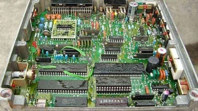
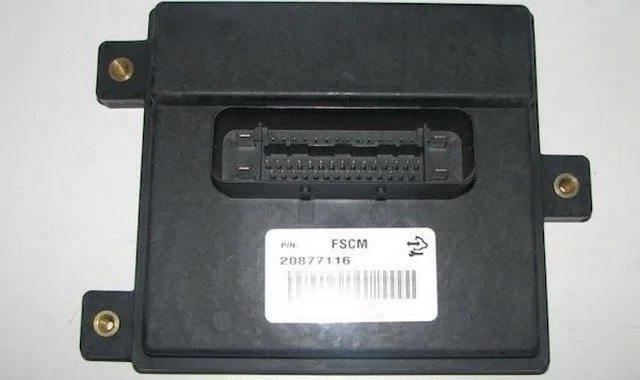
Example photo of a fuel pump control module:


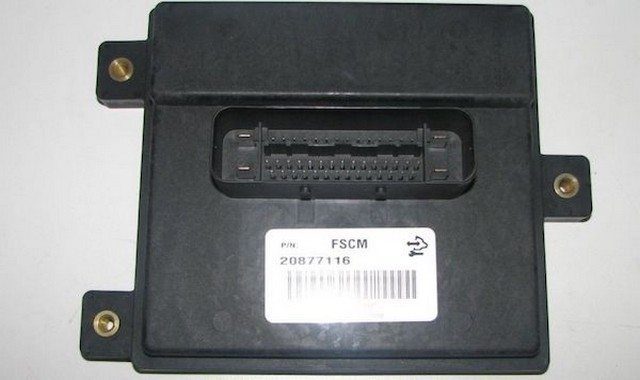
P0619 Fuel Pump Control Module
How Serious is this DTC?

Internal control module codes should always be taken seriously. A stored P0619 code can lead to various drivability issues because valuable controller memory may be lost.
What are some of the symptoms of the code?

Symptoms of a P0619 fault code may include:

Engine drivability problems
Engine stalling at idle
Delayed engine starting (especially when cold)
Other stored codes

What are some common causes of the code?

Causes

of this code may include:

Faulty AFCM / PCM
AFCM / PCM programming error
Open or shorted circuit or connectors in the CAN harness
AFCM / PCM power source failure
Insufficient control module ground

What are the P0619 troubleshooting steps?

Unfortunately, even the most experienced and well-equipped professional technician may find diagnosing a P0619 code quite difficult. There is also the issue of reprogramming. Without the necessary reprogramming equipment, it will be impossible to replace a faulty controller and perform a successful repair.

If AFCM/PCM power codes are present, they will need to be repaired before attempting to diagnose a P0619.

There are several preliminary tests that can be performed before declaring a controller faulty. A diagnostic scanner, a digital volt/ohmmeter (DVOM), and a reliable vehicle information source will be required.

Connect the scanner to the vehicle’s diagnostic port and retrieve all stored codes and freeze frame data. You will want to note this information, just in case the code proves to be intermittent. After recording all relevant information, clear the codes and test-drive the vehicle until the code resets or the PCM enters readiness mode. If the PCM enters readiness mode, the code is intermittent and will be more difficult to diagnose. The condition that caused the P0619 to be stored may even need to worsen before a diagnosis can be made. If the code resets, continue with this short list of preliminary tests.

When trying to diagnose a P0619, information can be your best tool. Search your vehicle information source for Technical Service Bulletins (TSBs) that parallel the stored code, the vehicle (year, make, model, and engine), and the symptoms presented. If you find the right TSB, it can provide diagnostic information that will help you significantly.

Use your vehicle information source to obtain connector face views, connector pinout diagrams, component locators, wiring schematics, and diagnostic flowcharts related to the code and the specific vehicle in question.

Use the DVOM to test the controller’s power fuses and relays. Replace blown fuses as needed. Fuses should be tested with the circuit loaded.

If all fuses and relays appear to be working as expected, a visual inspection of the wiring and harnesses related to the controller is necessary. You will also want to check the chassis and engine ground junctions. Use your vehicle information source to obtain ground locations for the related circuits. Use the DVOM to test ground integrity.

Visually inspect the system controllers for signs of water, heat, or collision damage. Any damaged controller, especially by water, should be considered faulty.

If the controller’s power and ground circuits are intact, suspect a faulty controller or a controller programming error. Replacing the controller will require reprogramming. In some cases, you can purchase pre-programmed controllers through aftermarket sources. Other vehicles/controllers will require on-board reprogramming that can only be performed by a dealer or another qualified source.

Unlike most other codes, P0619 is likely caused by a faulty controller or a controller programming error
Test the system ground integrity by connecting the DVOM’s negative test lead to ground and the positive test lead to battery voltage

P061A Internal Control Module Torque Performance

What Does It Mean?

This generic powertrain diagnostic trouble code (DTC) generally applies to many OBD-II vehicles. This may include, but is not limited to, vehicles from Dodge, Ram (Cummins), Ford (Powerstroke), Chrysler, Mitsubishi, Land Rover, Mercedes Benz, etc.

When a P061A code is stored, it means the Powertrain Control Module (PCM) has detected an internal performance error within the engine torque monitoring system. Other controllers may also detect an internal PCM performance error (related to the engine torque monitoring system) and contribute to the storage of a P061A code.

The internal control module monitoring processors are responsible for various controller self-test tasks and the overall responsibility of the internal control module. The input and output signals of the engine torque calculation system are self-tested and are continuously monitored by the PCM and other associated controllers. The Transmission Control Module (TCM), the Traction Control System Module (TCSM), and other controllers are subject to interaction with the engine torque monitoring system.

Engine torque is monitored (by the PCM and other controllers) using input signals from the Mass Air Flow (MAF) sensor and the Accelerator Pedal Position (APP) sensor (also known as the pedal position sensor). The desired or approximate required engine torque is calculated using the APP sensor, and the actual engine torque is calculated using data from the MAF sensor.

Whenever the ignition is turned on and the PCM is powered up, internal engine torque monitoring self-tests are initiated. In addition to running internal controller self-tests, the Controller Area Network (CAN) also compares the signals from each individual module to ensure all controllers are functioning correctly. These tests are performed simultaneously.

If the PCM detects a difference between the desired torque and the actual torque (more than 50 Newton-meters for more than one second) with an engine speed above 5000 RPM and a volumetric efficiency greater than 16%, a P061A code will be stored and the Malfunction Indicator Lamp (MIL) may illuminate. Multiple failure cycles may be required for the MIL to illuminate, depending on the perceived severity of the malfunction.

Photo of a PCM with the cover removed:


Powertrain Control Module PCM
How Severe Is This DTC?

  • Internal control module processor codes should be classified as severe.
  • A stored P061A code could lead to serious driving and fuel economy problems, suddenly and without warning.
  • What are some of the symptoms of the code?

Symptoms of a P061A trouble code may include:

  • Hesitation or stumbling during acceleration
  • Unresponsive acceleration
  • Reduced fuel efficiency
  • MAF or throttle actuator codes are also present

What are some common causes of the code?

Causes of this code may include:

  • Faulty electronic throttle control servo
  • Open or shorted circuit in the throttle control servo circuit
  • Clogged air filter element
  • Debris on the MAF sensor hot wire
  • Faulty APP/MAF sensor
  • Corroded MAF sensor electrical connector
  • PCM programming error or faulty PCM
  • Open or shorted circuits or connectors in the CAN bus
  • Insufficient control module ground
  • Open or shorted circuits between the APP/MAF sensor and the PCM

What are the P061A troubleshooting steps?

Even for the most experienced and well-equipped professional technician, diagnosing a P061A code can be very challenging. There is also the issue of reprogramming. Without the necessary reprogramming equipment, it will be impossible to replace a faulty controller and perform a successful repair.

If ECM/PCM power codes are present, they will obviously need to be rectified before attempting to diagnose a P061A. Furthermore, if there are MAF/APP sensor or Throttle Position Sensor (TPS) codes, these should be diagnosed and repaired first.

Follow the manufacturer’s recommendations for testing the MAF, APP, and TPS sensors. An oscilloscope can be particularly useful when testing APP and TPS sensors. Replace faulty components as necessary.

Several preliminary tests can be performed before declaring an individual controller faulty. A diagnostic scanner, a digital volt/ohmmeter (DVOM), and a reliable vehicle information source will be required. An oscilloscope may also prove useful.

Connect the scanner to the vehicle’s diagnostic port and retrieve all stored codes and freeze frame data. You will want to note this information, just in case the code proves to be intermittent. After recording all relevant information, clear the codes and test-drive the vehicle until the code resets or the PCM enters readiness mode. If the PCM enters readiness mode, the code is intermittent and will be more difficult to diagnose. The condition that caused the P061A to be stored may even need to worsen before a diagnosis can be made. If the code resets, proceed with this short list of preliminary tests.

When trying to diagnose a P061A, information can be your best tool. Search your vehicle information source for Technical Service Bulletins (TSBs) that correlate the stored code, the vehicle (year, make, model, and engine), and the symptoms presented. If you find the right TSB, it may provide diagnostic information that will assist you significantly.

Use your vehicle information source to obtain connector face views, connector pinout diagrams, component locators, wiring schematics, and diagnostic flowcharts related to the specific code and vehicle in question.

Use the DVOM to test the controller’s power fuses and relays. Test and replace blown fuses as needed. Fuses should be tested under load.

If all fuses and relays appear to be functioning as expected, a visual inspection of the wiring and harnesses related to the controller is necessary. You will also want to check the chassis and engine ground junctions. Use your vehicle information source to obtain ground locations for the related circuits. Use the DVOM to test ground integrity.

Visually inspect the system controllers for signs of water, heat, or collision damage. Any damaged controller, especially by water, should be considered faulty.

If the controller’s power and ground circuits are intact, suspect a faulty controller or a controller programming error. Replacing the controller will require reprogramming. In some cases, you can purchase pre-programmed controllers through aftermarket sources. Other vehicles/controllers will require on-board reprogramming that can only be performed by a dealership or another qualified source.

Unlike most other codes, P061A is likely caused by a faulty controller or a controller programming error.
Test the system ground integrity by connecting the DVOM’s negative test lead to ground and the positive test lead to battery voltage.

P061B Internal Control Module Torque Calculation Performance

What Does It Mean?

This generic powertrain diagnostic trouble code (DTC) generally applies to many OBD-II vehicles. This may include, but is not limited to, vehicles from Mazda, Ford, Mercedes Benz, Chevy, etc.

When a P061B code is stored, it means that the Powertrain Control Module (PCM) has detected an internal performance error in the engine torque monitoring system. Other controllers may also detect an internal PCM performance error (with the engine torque monitoring system) and contribute to storing a P061B.

The internal control module monitoring processors are responsible for various controller self-test tasks and the overall responsibility of the internal control module. The input and output signals of the engine torque calculation system are subjected to a self-test and are continuously monitored by the PCM and other associated controllers. The Transmission Control Module (TCM), the Traction Control System Module (TCSM), and other controllers are subject to interaction with the engine torque monitoring system.

Engine torque is monitored (by the PCM and other controllers) using input signals from the Mass Air Flow (MAF) sensor and the Accelerator Pedal Position (APP) sensor (also called the pedal position sensor). The desired or approximate required engine torque is calculated using the APP sensor, and the actual engine torque is calculated using MAF sensor data.

Whenever the ignition is turned on and the PCM is powered up, internal engine torque monitoring self-tests are initiated. In addition to running internal controller self-tests, the Controller Area Network (CAN) also compares the signals from each individual module to ensure all controllers are functioning correctly. These tests are performed simultaneously.

If the PCM detects a difference between the desired torque and the actual torque (more than 50 Newton meters for more than one second) with an engine speed above 5000 RPM and a volumetric efficiency greater than 16%, a P061B code will be stored and a Malfunction Indicator Lamp (MIL) may be illuminated. Multiple failure cycles may be required for the MIL to illuminate, depending on the perceived severity of the malfunction.

Photo of a PCM with the cover removed:


Powertrain Control Module PCM

How Severe is this DTC?

Internal control module processor codes should be classified as severe. A stored P061B code could lead to serious driving and fuel economy problems, suddenly and without warning.

What are some of the symptoms of the code?

Symptoms of a P061B fault code may include:

  • Hesitation or stumbling during acceleration
  • Acceleration becomes unresponsive
  • Reduced fuel efficiency
  • MAF or throttle actuator codes are also present

What are some of the common causes of the code?

Causes of this code may include:

  • Faulty electronic throttle control servo
  • Open or shorted circuit in the throttle control servo circuit
  • Clogged air filter element
  • Debris on the MAF sensor hot wire
  • Faulty APP / MAF sensor
  • Corroded MAF sensor electrical connector
  • PCM programming error or faulty PCM
  • Open or shorted circuit or connectors in the CAN bus
  • Insufficient control module ground
  • Open or shorted circuits between the APP / MAF sensor and the PCM

What are the troubleshooting steps for P061B?

Even for the most experienced and well-equipped professional technician, diagnosing a P061B code can be very challenging. There is also the issue of reprogramming. Without the necessary reprogramming equipment, it will be impossible to replace a faulty controller and perform a successful repair.

If ECM/PCM power codes are present, they will obviously need to be corrected before attempting to diagnose a P061B. Furthermore, if there are MAF/APP sensor or Throttle Position Sensor (TPS) codes, these must be diagnosed and repaired first.

Follow the manufacturer’s recommendations for testing the MAF, APP, and TPS sensors. An oscilloscope can be particularly useful when testing APP and TPS sensors. Replace faulty components as necessary.

Several preliminary tests can be performed before declaring an individual controller faulty. A diagnostic scanner, a digital volt/ohmmeter (DVOM), and a reliable vehicle information source will be needed. An oscilloscope may also prove useful.

Connect the scanner to the vehicle’s diagnostic port and retrieve all stored codes and freeze frame data. You will want to note this information, just in case the code turns out to be intermittent. After recording all relevant information, clear the codes and test drive the vehicle until the code resets or the PCM enters readiness mode. If the PCM enters readiness mode, the code is intermittent and will be more difficult to diagnose. The condition that caused the P061B to be stored may even need to worsen before a diagnosis can be made. If the code resets, continue with this short list of preliminary tests.

When trying to diagnose a P061B, information can be your best tool. Search your vehicle information source for Technical Service Bulletins (TSBs) that correlate the stored code, the vehicle (year, make, model, and engine), and the symptoms presented. If you find the right TSB, it can provide diagnostic information that will assist you significantly.

Use your vehicle information source to obtain connector face views, connector pinout diagrams, component locators, wiring schematics, and diagnostic flowcharts related to the code and the specific vehicle in question.

Use the DVOM to test the controller’s power fuses and relays. Test and replace blown fuses as needed. Fuses should be tested under load.

If all fuses and relays appear to be functioning as expected, a visual inspection of the wiring and harnesses related to the controller is necessary. You will also want to check the chassis and engine ground junctions. Use your vehicle information source to obtain ground locations for the related circuits. Use the DVOM to test ground integrity.

Visually inspect the system controllers for signs of water, heat, or collision damage. Any damaged controller, especially by water, should be considered faulty.

If the controller’s power and ground circuits are intact, suspect a faulty controller or a controller programming error. Replacing the controller will require reprogramming. In some cases, you can purchase pre-programmed controllers through aftermarket sources. Other vehicles/controllers will require on-board reprogramming that can only be performed by a dealer or another qualified source.

Unlike most other codes, P061B is likely caused by a faulty controller or a controller programming error.
Test the system ground integrity by connecting the DVOM’s negative test lead to ground and the positive test lead to battery voltage.

P061C Internal Control Module Engine Performance

What Does It Mean?

This generic powertrain diagnostic trouble code (DTC) typically applies to many OBD-II vehicles. This may include, but is not limited to, vehicles from Dodge, Ram (Cummins), Ford, Chrysler, etc.

When a P061C code is stored, it means the Powertrain Control Module (PCM) has detected an internal performance error within the engine speed (RPM) monitoring system. Other controllers may also detect an internal PCM performance error (related to the engine speed monitoring system) and contribute to storing a P061C.

The internal control module processor monitors are responsible for various controller self-test tasks and the overall responsibility of the internal control module. The input and output signals of the engine speed calculation system are self-tested and are continuously monitored by the PCM and other associated controllers. The Transmission Control Module (TCM), the Traction Control System Module (TCSM), and other controllers interact with the engine speed monitoring system.

The engine speed is monitored (by the PCM and other controllers) using input signals from the Crankshaft Position Sensor (CKP) and the Camshaft Position Sensor(s) (CMP). The desired engine speed is programmed into the PCM and other controllers. The actual engine speed is calculated using input data from the CKP and CMP sensors, as well as the Throttle Position Sensor (TPS) and other engine and transmission sensors. The desired speed is then compared to the actual speed.

Whenever the ignition is turned on and the PCM is powered up, internal engine speed monitoring self-tests are initiated. In addition to running internal controller self-tests, the Controller Area Network (CAN) also compares the signals from each individual module to ensure all controllers are functioning correctly. These tests are performed simultaneously.

If the PCM detects an internal error between the desired engine speed and the actual engine speed (which exceeds the maximum allowable threshold), a P061C code will be stored, and a Malfunction Indicator Lamp (MIL) may be illuminated. Several ignition cycles (with a fault) may be required for the MIL to illuminate.

Photo of a PCM with the cover removed:


Powertrain Control Module PCM
How Severe Is This DTC?

Internal control module processor codes should be classified as severe. A stored P061C code could lead to serious drivability and fuel economy issues, suddenly and without warning.
What Are Some of the Symptoms of the Code?

Symptoms of a P061C trouble code may include:

Hesitation or stumbling during acceleration
Engine misfires
Reduced power output
Engine misfire codes may also be present

What Are Some of the Common Causes of the Code?

Causes

of this code may include:

Faulty CKP / CMP sensor
CKP / CMP sensor connector contaminated with oil
PCM programming error or faulty PCM
Open or shorted circuit or connectors in the CAN bus
Insufficient control module ground
Open or shorted circuits between the CKP / CMP sensor(s) and the PCM

What Are the P061C Troubleshooting Steps?

Even for the most experienced and well-equipped professional technician, diagnosing a P061C code can be very challenging. There is also the issue of reprogramming. Without the necessary reprogramming equipment, it will be impossible to replace a faulty controller and perform a successful repair.

If ECM/PCM power codes are present, they will obviously need to be corrected before attempting to diagnose a P061C. Additionally, if there are CKP/CMP sensor or Throttle Position Sensor (TPS) codes, these should be diagnosed and repaired first.

Follow the manufacturer’s recommendations for testing the CKP, CMP, and TPS sensors. An oscilloscope can be particularly useful when testing electromagnetic sensors. Replace faulty components as necessary.

Several preliminary tests can be performed before declaring an individual controller faulty. A diagnostic scanner, a digital volt/ohmmeter (DVOM), and a reliable vehicle information source will be needed. An oscilloscope may also prove useful.

Connect the scanner to the vehicle’s diagnostic port and retrieve all stored codes and freeze frame data. You will want to note this information, just in case the code proves to be intermittent. After recording all relevant information, clear the codes and test drive the vehicle until the code resets or the PCM enters readiness mode. If the PCM enters readiness mode, the code is intermittent and will be more difficult to diagnose. The condition that caused the P061C to be stored may even need to worsen before a diagnosis can be made. If the code resets, proceed with this short list of preliminary tests.

When trying to diagnose a P061C, information can be your best tool. Search your vehicle information source for Technical Service Bulletins (TSBs) that correlate the stored code, the vehicle (year, make, model, and engine), and the symptoms presented. If you find the right TSB, it can provide diagnostic information that will help you significantly.

Use your vehicle information source to obtain connector face views, connector pinout diagrams, component locators, wiring schematics, and diagnostic flowcharts related to the specific code and vehicle in question.

Use the DVOM to test the controller’s power fuses and relays. Test and replace blown fuses as needed. Fuses should be tested under load.

If all fuses and relays appear to be functioning as expected, a visual inspection of the wiring and harnesses related to the controller is necessary. You will also want to check the chassis and engine ground junctions. Use your vehicle information source to obtain ground locations for the related circuits. Use the DVOM to test ground integrity.

Visually inspect the system controllers for signs of water, heat, or collision damage. Any damaged controller, especially by water, should be considered faulty.

If the controller’s power and ground circuits are intact, suspect a faulty controller or a controller programming error. Replacing the controller will require reprogramming. In some cases, you can purchase pre-programmed controllers through aftermarket sources. Other vehicles/controllers will require onboard reprogramming that can only be performed by a dealership or another qualified source.

Unlike most other codes, P061C is likely caused by a faulty controller or a controller programming error
Test the system ground integrity by connecting the DVOM’s negative test lead to ground and the positive test lead to battery voltage

P061D Internal Control Module Engine Air Mass Performance

What does it mean?

This generic powertrain diagnostic trouble code (DTC) generally applies to many OBD-II vehicles. This may include, but is not limited to, vehicles from Ford, Mazda, Chevrolet, Lincoln, etc.

When a P061D code is stored, it means that the Powertrain Control Module (PCM) has detected an internal performance error in the engine’s air mass monitoring system (Mass Air Flow – MAF). Other controllers may also detect an internal PCM performance error (with the engine speed monitoring system) and contribute to the storage of a P061D.

The internal control module monitoring processors are responsible for various controller self-test tasks and the overall responsibility of the internal control module. The input and output signals of the engine air mass calculation system are self-tested and are continuously monitored by the PCM and other associated controllers. The Transmission Control Module (TCM), the Traction Control System Module (TCSM), and other controllers interact with the engine air mass monitoring system.

The engine air mass is monitored (by the PCM and other controllers) using the input signals from the MAF sensor(s). The desired engine MAF is programmed into the PCM and other controllers. The actual engine air mass is calculated using input data from the MAF sensor, as well as the Throttle Position Sensor (TPS) and other engine and transmission sensors. The desired engine air mass is then compared to the actual engine air mass. After comparing the desired and actual engine air mass, the PCM makes the necessary adjustments to fuel delivery and ignition timing.

Whenever the ignition is turned on and the PCM is powered up, internal engine speed monitoring self-tests are initiated. In addition to running internal controller self-tests, the Controller Area Network (CAN) also compares the signals from each individual module to ensure all controllers are functioning correctly. These tests are performed simultaneously.

If the PCM detects an internal error in the desired engine air mass and the actual engine air mass (which exceeds the maximum allowed threshold), a P061D code will be stored and a Malfunction Indicator Lamp (MIL) may be illuminated. Several ignition cycles (with a fault) may be required for the MIL to illuminate.

Powertrain Control Module PCM
How severe is this DTC?

Internal control module processor codes should be classified as severe. A stored P061D code could lead to serious driving and fuel economy problems, suddenly and without warning.
What are some of the symptoms of the code?

Symptoms of a P061D fault code may include:

Hesitation or stumbling during acceleration
Engine misfires
Reduced power output
Engine misfire codes may also be present

What are some of the common causes of the code?

Causes

of this code may include:

Faulty MAF sensor
Corroded MAF sensor connector
PCM programming error or faulty PCM
Open or shorted circuit or connectors in the CAN harness
Insufficient control module ground
Open or shorted circuits between the MAF sensor and the PCM

What are the P061D troubleshooting steps?

Even for the most experienced and well-equipped professional technician, diagnosing a P061D code can be very challenging. There is also the issue of reprogramming. Without the necessary reprogramming equipment, it will be impossible to replace a faulty controller and perform a successful repair.

If ECM/PCM power codes are present, they will obviously need to be corrected before attempting to diagnose a P061D. Additionally, if MAF sensor or Throttle Position Sensor (TPS) codes are present, they must be diagnosed and repaired first.

Follow the manufacturer’s recommendations for testing MAF and TPS sensors. Replace faulty components as necessary.

Several preliminary tests can be performed before declaring an individual controller faulty. A diagnostic scanner, a digital volt/ohmmeter (DVOM), and a reliable source of vehicle information will be needed. An oscilloscope may also prove useful.

Connect the scanner to the vehicle’s diagnostic port and retrieve all stored codes and freeze frame data. You will want to note this information, just in case the code proves to be intermittent. After recording all relevant information, clear the codes and test-drive the vehicle until the code resets or the PCM enters readiness mode. If the PCM enters readiness mode, the code is intermittent and will be more difficult to diagnose. The condition that caused the P061D to be stored may even need to worsen before a diagnosis can be made. If the code resets, continue with this short list of preliminary tests.

When trying to diagnose a P061D, information can be your best tool. Search your vehicle information source for Technical Service Bulletins (TSBs) that correlate the stored code, the vehicle (year, make, model, and engine), and the symptoms presented. If you find the right TSB, it can provide diagnostic information that will help you significantly.

Use your vehicle information source to obtain connector face views, connector pinout diagrams, component locators, wiring schematics, and diagnostic flowcharts related to the specific code and vehicle in question.

Use the DVOM to test the controller’s power fuses and relays. Test and replace blown fuses as needed. Fuses should be tested with the circuit loaded.

If all fuses and relays appear to be functioning as expected, a visual inspection of the wiring and harnesses related to the controller is necessary. You will also want to check the chassis and engine ground connections. Use your vehicle information source to obtain ground locations for the related circuits. Use the DVOM to test ground integrity.

Visually inspect the system controllers for signs of water, heat, or collision damage. Any damaged controller, especially by water, should be considered faulty.

If the controller’s power and ground circuits are intact, suspect a faulty controller or a controller programming error. Replacing the controller will require reprogramming. In some cases, you can purchase pre-programmed controllers through aftermarket sources. Other vehicles/controllers will require on-board reprogramming that can only be performed by a dealership or another qualified source.

Unlike most other codes, P061D is likely caused by a faulty controller or a controller programming error
Test the system ground integrity by connecting the DVOM’s negative test lead to ground and the positive test lead to battery voltage

P061E Internal Control Module Brake Signal Performance

What does it mean?

This generic powertrain diagnostic trouble code (DTC) generally applies to many OBD-II vehicles. This may include, but is not limited to, vehicles from Dodge, Ram (Cummins), Ford, Chrysler, etc.

When a P061E code is stored, it means the Powertrain Control Module (PCM) has detected an internal performance error in the brake signal circuit. Other controllers may also detect an internal PCM performance error (with the engine speed monitoring system) and contribute to the storage of a P061E.

The internal control module monitoring processors are responsible for various controller self-test tasks and the overall responsibility of the internal control module. The input and output signals of the engine air mass calculation system are self-tested and are constantly monitored by the PCM and other associated controllers. The Transmission Control Module (TCM), the Traction Control System Module (TCSM), and other controllers are subject to interaction with the brake signal circuit.

The brake signal circuit (also called stop light) is monitored (by the PCM and other controllers) using the input signals from the brake pedal sensor. The brake signal circuit is an integral part of several control systems used in OBD-II vehicles. The cruise control and the transmission torque converter lockup system are just a few of the most common of these systems. The PCM and other controllers receive input signals from the stop light switch and use these inputs to activate and deactivate various functions accordingly. Brake signal inputs are generally limited to ON or OFF distinctions.

Whenever the ignition is turned on and the PCM is powered up, self-tests of the internal engine brake signal circuit are initiated. In addition to running internal controller self-tests, the Controller Area Network (CAN) also compares the signals from each individual module to ensure all controllers are functioning correctly. These tests are performed simultaneously.

If the PCM detects an internal error in the brake signal circuit, a P061E code will be stored and a Malfunction Indicator Lamp (MIL) may illuminate. Several ignition cycles (with a failure) may be required for the MIL to illuminate.

Powertrain Control Module PCM


How severe is this DTC?

Internal control module processor codes should be classified as severe. A stored P061E code could result in erratic operation of the transmission torque converter lockup or an inoperative cruise control (speed control).
What are some of the symptoms of the code?

Symptoms of a P061E fault code may include:

  • Harsh or delayed shifting (transmission)
  • Engine stalling at idle (while driving)
  • Inoperative brake lights (stop lights)
  • Lack of torque converter lockup may damage the transmission

What are some of the common causes of the code?

Causes of this code may include:

  • Faulty brake light switch
  • PCM programming error or faulty PCM
  • Open or shorted circuit or connectors in the CAN harness
  • Insufficient control module ground
  • Open or shorted circuits between the brake switch and the PCM

What are the P061E troubleshooting steps?

Even for the most experienced and well-equipped professional technician, diagnosing a P061E code can be very challenging. There is also the issue of reprogramming. Without the necessary reprogramming equipment, it will be impossible to replace a faulty controller and perform a successful repair.

If ECM/PCM power codes are present, they will obviously need to be corrected before attempting to diagnose a P061E. Additionally, if brake light switch/signal codes are present, these should be diagnosed and repaired first.

Follow the manufacturer’s recommendations for testing the brake light switches. Replace faulty components as necessary.

Several preliminary tests can be performed before declaring an individual controller faulty. A diagnostic scanner, a digital volt/ohmmeter (DVOM), and a reliable vehicle information source will be required. An oscilloscope may also prove useful.

Connect the scanner to the vehicle’s diagnostic port and retrieve all stored codes and freeze frame data. You will want to note this information, just in case the code proves to be intermittent. After recording all relevant information, clear the codes and test drive the vehicle until the code resets or the PCM enters readiness mode. If the PCM enters readiness mode, the code is intermittent and will be more difficult to diagnose. The condition which caused the P061E to be stored may even need to worsen before a diagnosis can be made. If the code resets, continue with this short list of preliminary tests.

When trying to diagnose a P061E, information can be your best tool. Search your vehicle information source for Technical Service Bulletins (TSBs) that parallel the stored code, the vehicle (year, make, model, and engine), and the symptoms presented. If you find the right TSB, it can provide diagnostic information that will help you significantly.

Use your vehicle information source to obtain connector face views, connector pinout diagrams, component locators, wiring schematics, and diagnostic flowcharts related to the code and the specific vehicle.

Use the DVOM to test the controller’s power fuses and relays. Test and replace blown fuses as needed. Fuses should be tested with the circuit loaded.

If all fuses and relays appear to be working as expected, a visual inspection of the wiring and harnesses related to the controller is necessary. You will also want to check the chassis and engine ground junctions. Use your vehicle information source to obtain ground locations for the related circuits. Use the DVOM to test ground integrity.

Visually inspect the system controllers for signs of water, heat, or collision damage. Any damaged controller, especially by water, should be considered faulty.

If the controller’s power and ground circuits are intact, suspect a faulty controller or a controller programming error. Replacing the controller will require reprogramming. In some cases, you can purchase pre-programmed controllers through aftermarket sources. Other vehicles/controllers will require onboard reprogramming that can only be performed by a dealer or another qualified source.

Unlike most other codes, P061E is likely caused by a faulty controller or a controller programming error.
Test the system ground integrity by connecting the DVOM’s negative test lead to ground and the positive test lead to battery voltage.

P061F Internal Control Module Brake Signal Performance

Fault Code P061F – Internal Performance Error of the Throttle Actuator Controller

DTC P061F: Generic OBD-II code related to the powertrain

What is the P061F Code?

Diagnostic code P061F indicates an internal error in the Powertrain Control Module (PCM), detected at the throttle actuator controller. It is common on vehicles equipped with a Drive-by-Wire (DBW) system, particularly Ford models (Mustang, F-150…).

Operation of the DBW System

The DBW system replaces the cable accelerator with an electric motor controlled by the PCM. It uses:

  • Accelerator Pedal Position (APP) sensors
  • Throttle Position (TPS) sensors

The PCM adjusts the throttle position based on signals from these sensors to precisely control acceleration.

Detection of Code P061F

When the ignition is turned on, the PCM performs self-tests. If an inconsistency is detected between TPS/APP signals or between modules, code P061F is stored and may trigger the Malfunction Indicator Lamp (MIL) and switch to limp mode.

Severity of the Code

Code P061F is serious. It can cause:

  • Limited or no acceleration
  • Stuck throttle
  • Irregular idle
  • Reduced performance
  • Increased fuel consumption

Possible Causes of Code P061F

  • Faulty DBW actuator motor
  • Failed TPS or APP sensor
  • PCM programming error
  • Damaged or shorted wiring harness
  • Module ground issue
  • Faulty PCM

Recommended Diagnostic Steps

  1. Scan the vehicle to read codes and freeze frame data
  2. Clear codes, then test again to see if the code returns
  3. Check Technical Service Bulletins (TSBs) related to your model
  4. Test APP and TPS sensors with a multimeter (DVOM)
  5. Check PCM power supplies and grounds
  6. Inspect wiring, connectors, relays, and fuses
  7. Test the throttle actuator motor
  8. Replace or reprogram the PCM if necessary (by a professional)

⚠️ Warning: Reprogramming requires specific equipment. In some cases, the PCM must be replaced with a pre-programmed unit.

Published on eobdcode.com – Your reference for OBD-II diagnostic codes

P0620 Generator Control Circuit Malfunction

What does it mean?

This is a generic diagnostic trouble code (DTC) and applies to many OBD-II vehicles (1996-newer). This may include, but is not limited to, vehicles from Hyundai, Mercedes-Benz, Buick, Ford, GMC, Chevrolet, Jeep, Cadillac, etc. Although generic, the specific repair steps may vary depending on the year, make, model, and powertrain configuration.


A stored P0620 code means that the Powertrain Control Module (PCM) has detected a malfunction in the generator control circuit.

The PCM typically powers up and monitors the generator control circuit whenever the engine is running.

Whenever the ignition is turned on and the PCM is powered up, several controller self-tests are performed. In addition to running internal controller self-tests, the Controller Area Network (CAN) is used to compare signals from each individual module to ensure that the various controllers interact correctly.

If a problem is detected in the monitoring of the generator control circuit, a P0620 code will be stored and a Malfunction Indicator Lamp (MIL) may be illuminated. Depending on the perceived severity of the malfunction, several failure cycles may be required for the MIL to light up.

A typical alternator:


P0620 Alternator
How serious is this DTC?

Internal control module codes should always be taken seriously. A stored P0620 code can lead to various driving issues, including a no-start condition and/or a dead battery.
What are some of the symptoms of the code?

Symptoms of a P0620 fault code may include:

Engine driving issues
Engine stalling at idle
Delayed engine starting (especially when cold)
Other stored codes

What are some common causes of the code?

Causes

of this code may include:

Faulty PCM
PCM programming error
Open or shorted generator control circuit
Faulty generator assembly
Insufficient control module ground

What are the troubleshooting steps for P0620?

A diagnostic scanner, a battery/alternator tester, a digital volt/ohmmeter (DVOM), and a reliable source of vehicle information will be needed to diagnose a P0620 code.

Check your vehicle information source for Technical Service Bulletins (TSBs) that relate to the stored code, the vehicle (year, make, model, and engine), and the symptoms presented. If you find the relevant TSB, it may provide diagnostic information that will significantly assist you.

Start by connecting the scanner to the vehicle’s diagnostic port and retrieving all stored codes and freeze frame data. You’ll want to note this information, just in case the code proves to be intermittent. After recording all relevant information, clear the codes and test-drive the vehicle until the code resets or the PCM enters readiness mode. If the PCM enters readiness mode, the code is intermittent and will be more difficult to diagnose. The condition that caused the P0620 to be stored may even need to worsen before a diagnosis can be made. If the code resets, continue with your diagnosis.

Use the battery/alternator tester to test the battery and ensure it is sufficiently charged. If not, test the alternator/generator. Follow the manufacturer’s recommended specifications for minimum and maximum voltage output requirements for the battery and alternator. If the alternator/generator is not charging, proceed to the next step in your diagnosis.

Use your vehicle information source to obtain connector face views, connector pinout diagrams, component locators, wiring diagrams, and diagnostic flowcharts related to the code and the specific vehicle in question.

Check for battery voltage at the alternator/generator using the appropriate wiring diagram and your DVOM. If not present, check the system fuses and relays and replace faulty parts as needed. If all fuses and relays are functioning normally, suspect a faulty alternator/generator.

If the alternator is charging and the P0620 continues to reset, use the DVOM to test the controller power fuses and relays. Replace blown fuses as needed. Fuses should be tested under load.

If all fuses and relays appear to be functioning as expected, a visual inspection of the wiring and harnesses related to the controller is necessary. You will also want to check the chassis and engine ground connections. Use your vehicle information source to obtain ground locations for the related circuits. Use the DVOM to test ground integrity.

Visually inspect the system controllers for signs of water, heat, or collision damage. Any damaged controller, especially by water, should be considered faulty.

If the controller power and ground circuits are intact, suspect a faulty controller or a controller programming error. Replacing the controller will require reprogramming. In some cases, you can purchase pre-programmed controllers through aftermarket sources. Other vehicles/controllers will require on-board reprogramming that can only be performed by a dealer or another qualified source.

P0621 Generator Lamp Control Circuit Malfunction L

What does it mean?

This is a generic diagnostic trouble code (DTC) and applies to many OBD-II vehicles (1996-newer). This may include, but is not limited to, vehicles from Chevy, Saturn, GMC, Opel, Porsche, Pontiac, etc. Although generic, the exact repair steps may vary depending on the year, make, model, and powertrain configuration.


A stored P0621 code means that the Powertrain Control Module (PCM) has detected a malfunction in the generator lamp control circuit. The L simply reiterates the lamp control circuit.

The generator lamp is located in the dashboard. Its main purpose is to warn the driver of potential charging system problems when it is illuminated.

The PCM typically monitors the continuity of the generator lamp control circuit whenever the engine is running. The generator lamp control circuit is an integral part of the generator’s operation and maintaining battery charge levels.

Whenever the ignition is turned on and the PCM is powered, several controller self-tests are performed. In addition to running internal controller self-tests, the Controller Area Network (CAN) is used to compare signals from each individual module to ensure that the various controllers interface correctly.

If a problem is detected in the monitoring of the generator lamp control circuit, a P0621 code will be stored and a Malfunction Indicator Lamp (MIL) may illuminate. Depending on the perceived severity of the malfunction, several failure cycles may be required for the MIL to illuminate.

P0621 Alternator


How severe is this DTC?

Internal control module codes should always be taken seriously. A stored P0621 code could lead to various driving problems, including a no-start condition and/or a dead battery.
What are some of the symptoms of the code?

Symptoms of a P0621 fault code may include:

    Engine driving problems
    Rough engine idle
    Engine stalling inadvertently
    Delayed engine starting
    Other stored codes

What are some of the common causes of the code?

Causes

of this code may include:

    Faulty PCM
    PCM programming error
    Open or shorted generator lamp control circuit
    Faulty alternator/generator
    Faulty generator lamp bulb

What are the troubleshooting steps for P0621?

A diagnostic scanner, a battery/alternator tester, a digital volt/ohmmeter (DVOM), and a reliable source of vehicle information will be needed to diagnose a P0621 code.

Consult your vehicle’s information source for Technical Service Bulletins (TSBs) that match the stored code, the vehicle (year, make, model, and engine), and the symptoms presented. If you find the appropriate TSB, it may provide useful diagnostics.

Start by connecting the scanner to the vehicle’s diagnostic port and retrieving all stored codes and freeze frame data. You will want to note this information, just in case the code proves to be intermittent. After recording all relevant information, clear the codes and test the vehicle until the code resets or the PCM enters readiness mode. If the PCM enters readiness mode, the code is intermittent and will be more difficult to diagnose. The condition that caused the P0621 to be stored may even need to worsen before a diagnosis can be made. If the code resets, continue with your diagnosis.

Use the battery/alternator tester to test the battery and ensure it is sufficiently charged. If not, charge the battery as recommended and test the alternator/generator. Follow the manufacturer’s recommended specifications for minimum and maximum voltage output requirements for the battery and alternator. If the alternator/generator is not charging, proceed to the next step in your diagnosis.

Use your vehicle information source to obtain connector face views, connector pinout diagrams, component locators, wiring diagrams, and diagnostic flowcharts related to the code and the vehicle in question.

Check for battery voltage on the alternator/generator warning lamp circuit using the appropriate wiring diagram and your DVOM. If not, check the system fuses and relays and replace faulty parts as needed. If voltage is found at the generator warning lamp, suspect a faulty alternator/generator warning bulb.

If the alternator is charging, the alternator/generator warning lamp bulb is functioning correctly, and the P0621 continues to reset, use the DVOM to test the controller power fuses and relays. Replace blown fuses as needed. Fuses should be tested with the circuit loaded.

If all fuses and relays appear to be functioning as expected, a visual inspection of the wiring and harnesses related to the controller is necessary. You will also want to check the chassis and engine ground connections. Use your vehicle information source to obtain ground locations for related circuits. Use the DVOM to test ground integrity.

Visually inspect the system controllers for signs of water, heat, or collision damage. Any damaged controller, especially environmentally damaged by water, should be considered faulty.

If the controller power and ground circuits are intact, suspect a faulty controller or a controller programming error. Replacing the controller will require reprogramming. In some cases, you can purchase pre-programmed controllers through aftermarket sources. Other vehicles/controllers will require on-board reprogramming that can only be performed by a dealer or other qualified source.

     If the charge lamp does not illuminate during key-on engine-off (KOEO) conditions, suspect a faulty generator warning lamp bulb
     Test the controller ground integrity by connecting the DVOM’s negative test lead to ground and the positive test lead to battery voltage

P0622 Generator F Field Control Circuit Malfunction

What does it mean?

This is a generic diagnostic trouble code (DTC) and applies to many OBD-II vehicles (1996-newer). This may include, but is not limited to, Dodge, Jeep, Chevy, Ford, Land Rover, Toyota, Ram, etc. vehicles. Although generic, the specific repair steps may vary depending on the year, make, model, and powertrain configuration.

A stored P0622 code means that the Powertrain Control Module (PCM) has detected a malfunction with the generator field coil control circuit. The F simply reiterates that the field coil control circuit is at fault.

The field coil is probably most recognizable by its windings, which are visible through the ventilation holes of most alternators. The field coil surrounds the generator armature and remains stationary within the alternator housing.

The PCM monitors the continuity and voltage level of the generator field control circuit whenever the engine is running. The generator field coil is integral to the operation of the generator and maintaining the battery’s charge levels.

Whenever the ignition is turned on and the PCM is powered up, several controller self-tests are performed. In addition to running internal controller self-tests, the Controller Area Network (CAN) is used to compare signals from each individual module to ensure the various controllers interface correctly.

If a problem is detected in the monitoring of the generator field control circuit, a P0622 code will be stored and a Malfunction Indicator Lamp (MIL) may be illuminated. Depending on the perceived severity of the malfunction, multiple failure cycles may be required for the MIL to illuminate.

A typical alternator:


P0622 Alternator
How severe is this DTC?

Internal control module codes should be considered severe. A stored P0622 code could lead to various driving issues, including a no-start and/or dead battery condition.
What are some of the symptoms of the code?

Symptoms of a P0622 trouble code may include:

Engine driveability problems
Rough engine idle
Inadvertent engine stalling
Delayed engine starting
Other stored codes

What are some common causes of the code?

Causes

of this code may include:

Faulty PCM
PCM programming error
Open or shorted generator field control circuit
Faulty alternator/generator

What are the P0622 troubleshooting steps?

A diagnostic scanner, a battery/alternator tester, a digital volt/ohmmeter (DVOM), and a reliable source of vehicle information will be needed to diagnose a P0622 code.

Consult your vehicle information source for Technical Service Bulletins (TSBs) that match the stored code, the vehicle (year, make, model, and engine), and the presented symptoms. If you find the relevant TSB, it may provide helpful diagnostics.

Start by connecting the scanner to the vehicle’s diagnostic port and retrieving all stored codes and freeze frame data. You’ll want to note this information, just in case the code proves to be intermittent. After recording all relevant information, clear the codes and test-drive the vehicle until the code resets or the PCM enters readiness mode. If the PCM enters readiness mode, the code is intermittent and will be more difficult to diagnose. The condition that caused the P0622 to be stored may even need to worsen before a diagnosis can be made. If the code resets, continue with your diagnosis.

Use the battery/alternator tester to check the battery’s charge and ensure it is sufficiently charged. If not, charge the battery as recommended and test the alternator/generator. Follow the manufacturer’s recommended specifications for minimum and maximum voltage output requirements for the battery and alternator. If the alternator/generator is not charging, proceed to the next step of your diagnosis.

Use your vehicle information source to obtain connector face views, connector pinout diagrams, component locators, wiring schematics, and diagnostic flowcharts related to the code and the specific vehicle.

Check for battery voltage at the alternator/generator field control circuit using the appropriate wiring schematic and your DVOM. If not present, check the system fuses and relays and replace faulty components as needed. If voltage is found at the generator field coil control terminal, suspect a faulty alternator/generator.

If the alternator is charging and the P0622 continues to reset, use the DVOM to test the controller power fuses and relays. Replace any blown fuses as needed. Fuses should be tested under load.

If all fuses and relays appear to be functioning as expected, a visual inspection of the wiring and harnesses related to the controller is necessary. You will also want to check the chassis and engine ground connections. Use your vehicle information source to obtain ground locations for the related circuits. Use the DVOM to test ground integrity.

Visually inspect the system controllers for signs of water, heat, or collision damage. Any damaged controller, especially by water, should be considered faulty.

If the controller power and ground circuits are intact, suspect a faulty controller or a controller programming error. Replacing the controller will require reprogramming. In some cases, you can purchase pre-programmed controllers from aftermarket sources. Other vehicles/controllers will require on-board reprogramming that can only be performed by a dealer or other qualified source.

The field coil is an integral part of the alternator and generally cannot be replaced separately
Test the controller ground integrity by connecting the DVOM’s negative test lead to ground and the positive test lead to battery voltage