What Does It Mean?
This generic powertrain diagnostic trouble code (DTC) typically applies to many OBD-II vehicles. This may include, but is not limited to, vehicles from Mazda, Ford, Honda, Chevrolet, Jeep, Dodge, etc.
When a P060F code is stored, it means the Powertrain Control Module (PCM) has detected an internal performance error with the Engine Coolant Temperature (ECT) sensor circuit. Other controllers may also detect an internal PCM performance error (in the ECT sensor circuit) and contribute to storing a P060F.
The internal control module monitoring processors are responsible for various controller self-test tasks and the overall responsibility of the internal control module. The input and output signals of the ECT sensor are self-tested and are constantly monitored by the PCM and other associated controllers. The Transmission Control Module (TCM), Traction Control System Module (TCSM), and other controllers are subject to interaction with the ECT sensor.
ECT sensors are composed of a thermistor that is dipped in hard resin and sealed in a metal or plastic housing. Brass is the most commonly used metal as the ECT sensor housing material. The ECT housing is designed to be screwed into a coolant passage in the engine intake manifold, cylinder head, or block. When hot coolant flows through the passages and past the ECT sensor, the resistance level of the thermistor in the ECT sensor decreases. When the engine coolant decreases in temperature, the resistance increases and the ECT sensor circuit voltage is reduced accordingly. These resistance fluctuations (which cause circuit voltage variations) are interpreted by the PCM as changes in engine coolant temperature. ECT sensor input data is essential in calculating fuel delivery and ignition timing strategy.
Whenever the ignition is turned on and the PCM is powered up, self-tests of the internal ECT circuit are initiated. In addition to performing internal controller self-tests, the Controller Area Network (CAN) also compares the signals from each individual module to ensure all controllers are functioning correctly. These tests are performed simultaneously.
If the PCM detects a discrepancy between any of the onboard controllers, which would indicate an internal ECT sensor error, a P060F code will be stored and a Malfunction Indicator Lamp (MIL) may be illuminated. Several failure cycles may be required for MIL illumination, depending on the perceived severity of the malfunction.
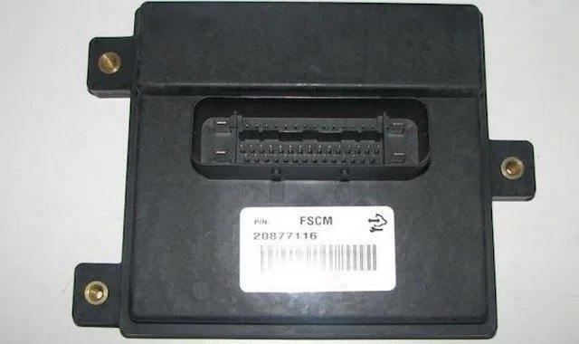
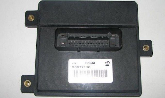
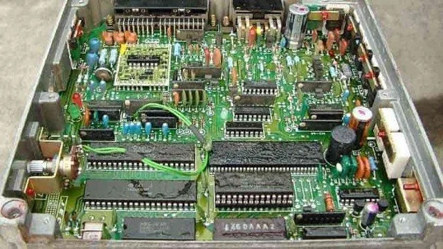
Photo of a PCM with the cover removed:

Powertrain Control Module PCM
How Serious is this DTC?
Internal control module processor codes should be classified as severe. A stored P060F code could lead to serious drivability and fuel economy problems, suddenly and without warning.
What are Some of the Symptoms of the Code?
Symptoms of a P060F trouble code may include:
Drivability issues (especially during startup)
Harsh or erratic automatic transmission shifting
Reduced fuel efficiency
Rough idle or stalling (especially at idle)
Hesitation during acceleration
What are Some of the Common Causes of the Code?
Causes
of this code may include:
Faulty controller or controller programming error
Open or shorted circuit or connectors in the CAN bus
Insufficient control module ground
Faulty ECT sensor
Corroded electrical connector (ECT)
Open or shorted circuits between the ECT sensor and the PCM
What are the P060F Troubleshooting Steps?
Even for the most experienced and well-equipped professional technician, diagnosing a P060F code can prove very difficult. There is also the issue of reprogramming. Without the necessary reprogramming equipment, it will be impossible to replace a faulty controller and perform a successful repair.
If ECM/PCM power codes are present, they will obviously need to be corrected before attempting to diagnose a P060F. Furthermore, if there are ECT sensor codes, these should be diagnosed and repaired first.
Several preliminary tests can be performed before declaring an individual controller faulty. A diagnostic scanner, a digital volt/ohmmeter (DVOM), and a reliable vehicle information source will be needed. An infrared thermometer with a laser pointer may be helpful.
Connect the scanner to the vehicle’s diagnostic port and retrieve all stored codes and freeze frame data. You will want to note this information, just in case the code proves to be intermittent. After recording all relevant information, clear the codes and test drive the vehicle until the code resets or the PCM enters readiness mode. If the PCM enters readiness mode, the code is intermittent and will be more difficult to diagnose. The condition which caused the P060F to be stored may even need to worsen before a diagnosis can be made. If the code resets, continue with this short list of preliminary tests.
When trying to diagnose a P060F, information can be your best tool. Research your vehicle information source for Technical Service Bulletins (TSBs) that parallel the stored code, the vehicle (year, make, model, and engine), and the symptoms presented. If you find the right TSB, it can provide diagnostic information that will assist you significantly.
Use your vehicle information source to obtain connector face views, connector pinout diagrams, component locators, wiring schematics, and diagnostic flowcharts related to the code and the specific vehicle.
Use the DVOM to test the controller power fuses and relays. Test and replace blown fuses as needed. Fuses should be tested with the circuit loaded.
If all fuses and relays appear to be working as expected, a visual inspection of the wiring and harnesses related to the controller is in order. You will also want to check the chassis and engine ground junctions. Use your vehicle information source to obtain ground locations for the related circuits. Use the DVOM to test ground integrity.
Visually inspect the system controllers for signs of water, heat, or collision damage. Any damaged controller, especially by water, should be considered faulty.
If the controller power and ground circuits are intact, suspect a faulty controller or a controller programming error. Replacing the controller will require reprogramming. In some cases, you can purchase pre-programmed controllers through aftermarket sources. Other vehicles/controllers will require onboard reprogramming that can only be performed by a dealership or another qualified source.
Testing the ECT Sensor and Circuits
Any stored ECT sensor-related code warrants checking to ensure the engine is not overheating. It should be full of coolant and operating within the acceptable temperature range.
Probe the ECT sensor connector reference circuit pin using the DVOM’s positive test lead. Use the negative test lead to probe the ground pin.
With the key on and engine off (KOEO), test for reference voltage (usually 5 volts) and a ground at the ECT sensor connector.
If reference voltage and ground are present on the respective connector pins, plug the sensor connector back in. Probe the ECT sensor signal circuit with the DVOM’s positive test lead (negative probe connected to a known good engine ground). Use the infrared thermometer to check the actual coolant temperature. Consult the temperature-to-voltage chart (found in the vehicle information source). With it, you can determine if the ECT sensor is functioning correctly by comparing the actual voltage with the desired voltage.
If the ECT sensor does not reflect the correct amount of voltage (based on the actual coolant temperature), suspect it is faulty.
If the ECT sensor signal circuit reflects the correct voltage level, use the DVOM to test the signal circuit at the PCM connector. If there is no sensor signal at the PCM connector but it is detected at the sensor connector, an open circuit exists between the two components.
Unlike most other codes, P060F is likely caused by a faulty controller or a controller programming error
Test system ground integrity by connecting the DVOM’s negative test lead to ground and the positive test lead to battery voltage