Understanding the OBD-II Trouble Code P1443
When your vehicle’s check engine light illuminates and a diagnostic scan reveals the OBD2 code P1443, you are dealing with a specific fault within the Evaporative Emission Control (EVAP) system. This diagnostic trouble code (DTC) is defined as “Evaporative Emission Control System Leak Detection Pump Control Circuit.” The EVAP system is a critical component of your vehicle’s emissions control network, designed to prevent fuel vapors from the gas tank from escaping into the atmosphere. The Leak Detection Pump (LDP) is the heart of the leak monitoring process in many modern vehicles, particularly those from manufacturers like Nissan, Infiniti, and Chrysler. A P1443 code indicates that the vehicle’s Powertrain Control Module (PCM) has detected an electrical malfunction within the control circuit for this pump.
What is the EVAP System and Why is it Important?
The Evaporative Emission Control (EVAP) system is a sealed network that captures fuel vapors from the fuel tank. Instead of being released into the air, these vapors are stored temporarily in a charcoal-filled canister. When the engine is running under specific conditions, the PCM opens a purge valve, allowing these stored vapors to be drawn into the engine and burned. This process is environmentally responsible and improves overall fuel efficiency. The system must remain completely sealed for this process to work effectively. The Leak Detection Pump’s job is to pressurize the system and monitor for any drops in pressure that would indicate a leak.
The Role of the Leak Detection Pump (LDP)
The Leak Detection Pump is an electrically-operated pump and switch assembly. It is not a traditional fluid pump; rather, it uses engine vacuum to draw in air and then uses an internal solenoid to seal that air in, creating pressure within the EVAP system. The PCM sends a voltage signal to the LDP’s solenoid to control its operation. The PCM then monitors the feedback from the LDP’s internal pressure switch. Code P1443 is set specifically when the PCM detects a problem with the *control circuit*—the electrical pathway between the PCM and the LDP solenoid. This distinguishes it from codes related to mechanical pump failure or leaks in the hoses.
Common Symptoms and Causes of a P1443 Code
A P1443 code represents an electrical fault, which may or may not produce noticeable drivability symptoms. However, because it affects the emissions system, it should not be ignored.
Recognizing the Symptoms of P1443
- Illuminated Check Engine Light (MIL): This is the most common and often the only symptom.
- Failed Emissions Test: The vehicle will not pass a state or local emissions inspection.
- Fuel Odor: In some cases, a failing LDP or related leak may cause a faint smell of gasoline.
- Other EVAP Codes: P1443 may appear alongside other EVAP codes like P0442 or P0455 if the underlying issue is causing a leak.
Since the LDP’s function is part of a non-continuous self-test, you likely will not notice any difference in engine performance, fuel economy, or starting.
Primary Causes of the P1443 Diagnostic Trouble Code
- Faulty Leak Detection Pump (LDP): The internal solenoid within the pump can fail electrically.
- Damaged Wiring or Connectors: The wiring harness connecting the PCM to the LDP can suffer from chafing, corrosion, or broken wires.
- Poor Electrical Connections: A loose or corroded connector at the LDP or the PCM can interrupt the control signal.
- Blown Fuse: A fuse that supplies power to the EVAP system components may be blown.
- Defective Powertrain Control Module (PCM): While rare, a failure within the PCM itself can prevent it from sending the proper control signal.
Step-by-Step Diagnostic and Repair Procedure
Diagnosing a P1443 code requires a methodical approach, a digital multimeter (DMM), and a reliable wiring diagram for your specific vehicle. Always begin with the simplest and most cost-effective checks.
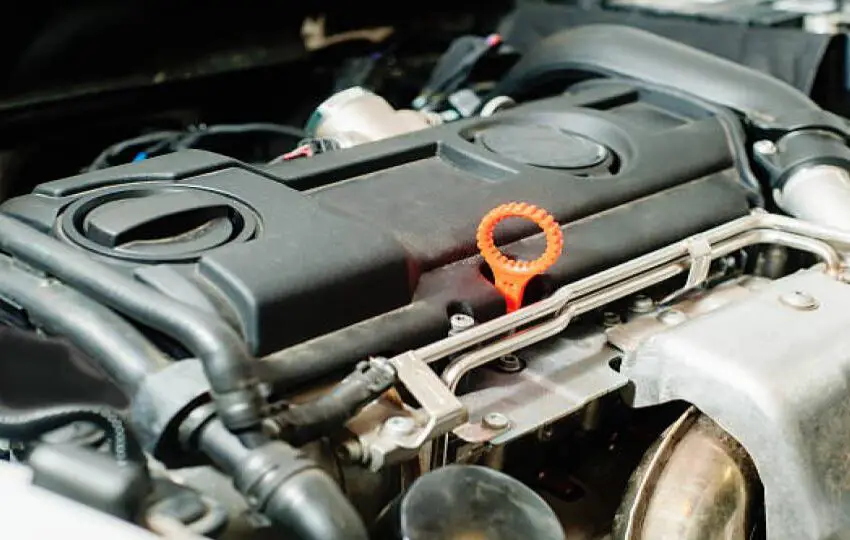
Initial Visual Inspection and Preliminary Checks
Before diving into electrical testing, a thorough visual inspection can often reveal the problem quickly and save valuable time.
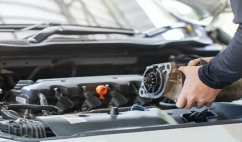
- Locate the LDP: Consult your vehicle’s service manual. The LDP is often located in the engine bay, near the EVAP canister, or behind a rear wheel well liner.
- Inspect Wiring and Connectors: Carefully examine the entire wiring harness leading to the LDP. Look for any obvious damage, such as burnt, chafed, or broken wires. Check the connector for pushed-out pins, corrosion, or moisture.
- Check Related Fuses: Locate and inspect all fuses related to the EVAP system and the PCM in the under-hood and interior fuse boxes.
Electrical Circuit Testing with a Multimeter
If the visual inspection is inconclusive, you must verify the integrity of the control circuit. You will need a wiring diagram to identify the correct pins.
- Test for Power and Ground: With the connector disconnected from the LDP, turn the ignition to “ON.” Check for battery voltage at the power supply wire to the LDP. Also, verify a clean ground connection.
- Test the Control Circuit from the PCM: This is a critical test. Using the wiring diagram, back-probe the control circuit wire at the LDP connector. With a scan tool that can command the LDP on/off, or by monitoring the circuit during a key cycle, you should see the PCM switching the voltage on and off. If there is no signal, the problem is in the wiring or the PCM.
- Check for Shorts and Resistance: Use the multimeter’s resistance (ohms) setting to check for short-to-power or short-to-ground on the control circuit wire. Also, check the resistance of the LDP solenoid itself; compare it to the manufacturer’s specification (typically a low resistance, often between 10-30 ohms). An infinite reading indicates an open solenoid, while a zero reading indicates a short.
Component Replacement and Final Verification
Once you have isolated the faulty component, replacement is the next step.
- Replacing the Leak Detection Pump: If the LDP solenoid tests bad, replace the entire LDP assembly. It is generally not serviceable separately.
- Repairing Wiring: If the wiring is damaged, repair or replace the affected section using proper solder and heat shrink tubing. Do not use twist-on connectors.
- Clearing the Code and Test Drive: After the repair, clear the P1443 code with your scan tool. To ensure the repair was successful, the PCM needs to run a complete EVAP monitor self-test. This often requires a specific drive cycle. Once the monitor runs and passes, the code should not return, confirming a successful repair.
Professional Insight and Technical Considerations
While a P1443 is a circuit code, it’s essential to understand the context in which it operates. The EVAP system is a complex network, and a thorough diagnosis is key to a cost-effective repair.
Why a P1443 is a “Hard” Code
Unlike some codes that can be intermittent, P1443 is typically a “hard” fault. This means the PCM has detected a consistent open, short, or out-of-range signal on the control circuit. It is unlikely to clear on its own and will require physical diagnosis and repair.
Vehicle-Specific Nuances
This code is particularly common on Nissan and Infiniti vehicles. On these models, the LDP is often a known failure point. Using a high-quality OEM or OEM-equivalent replacement part is highly recommended for these applications to ensure longevity and proper system operation. Always cross-reference the symptoms and tests with a vehicle-specific service manual or reliable database, as connector pinouts and component locations vary significantly between makes and models.