When it comes to car modifications, some upgrades genuinely enhance performance and style. But other misguided attempts at car customization are simply useless, tacky, or even ridiculous.
Get ready to shake your head and laugh at giant wings meant for flight, obnoxious neon lights, and ridiculous modifications that have nothing to do with vehicles.
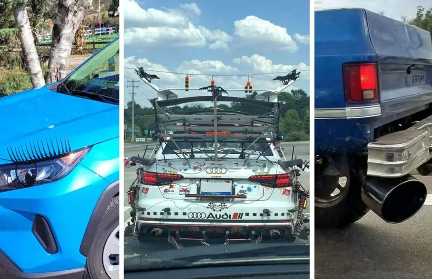
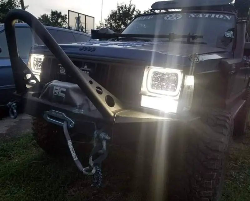
#1 – Tinted Headlights/Taillights
Deliberately reducing the amount of light emitted to see (and be seen) at night might be one of the dumbest mods ever created. Aftermarket shaded tints on headlights and taillights aim to look menacing but often cause blindness.
But even legal levels of overlays and smoked lenses often trigger fix-it tickets by obscuring lighting clarity. Beyond reduced functionality, tinted lights complicate bulb replacement. Your ride should illuminate confidence through clarity, not squinting to see and be seen through dark lighting mods.
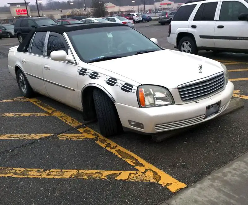
#2 – Extremely Lowered Suspension

An impractical car mod is when owners lower their vehicle so low that the car literally scrapes the ground. Even though a slight drop can improve handling, some go to the extreme, lowering their car an inch from the curb.
While giving your vehicle a stunning look, it also destroys maneuverability as your undercarriage eats speed bumps and you get stuck on parking curbs.
#3 – Neon Underbody Lighting
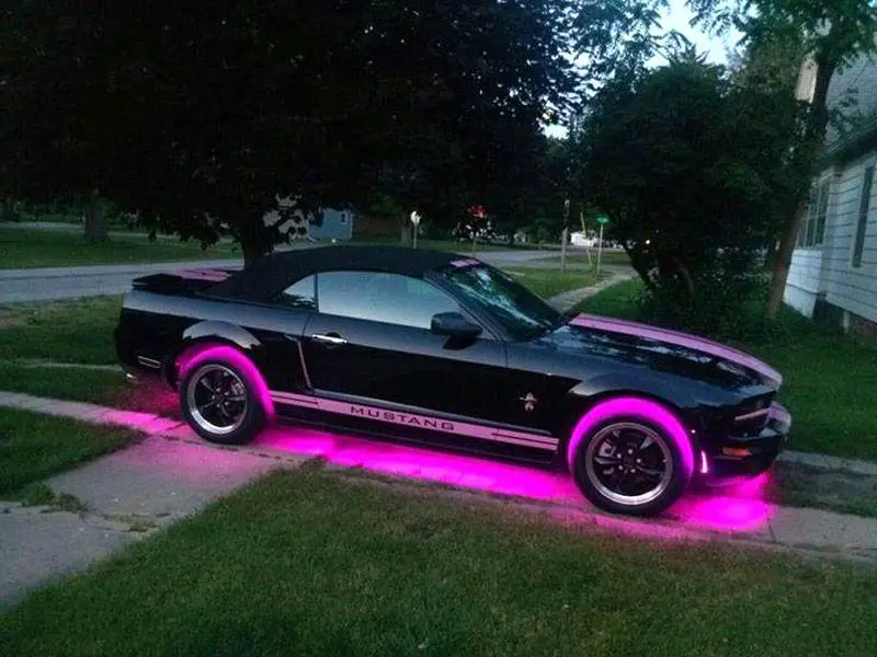
Nothing screams ‘I make questionable life choices’ like neon lights installed under your car. Even though some ambient lighting can be cool inside, underbody neon belongs in the ’90s with Reebok Pumps. Sure, it might give your Civic a cyberpunk vibe, but it ruins any attempt to look stylish.
The only things that light up underbody kits are speed bumps and road accidents. So if you want the glowing-in-the-dark aesthetic of a radioactive spaceship, save your money and drive near Chernobyl instead. Neon underbody lighting is tacky and totally useless.
#4 – Lambo Doors
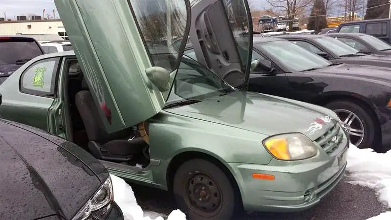
Unless you’re driving a Lamborghini with real scissor doors, spending a lot of money to modify your doors so they open vertically screams midlife crisis more than performance upgrade. Sure, scissor doors look sleek on a Diablo, but they don’t belong on your 10-year-old sedan.
Lambo door kits are notoriously finicky, turning your doors into failure-prone birds of prey. Lambo doors belong on Lambos, not your project car.
#5 – Clear Turn Signals
Clear turn signals might seem discreet but reduce visibility and safety. Replacing orange bulbs with clear ones hides turn intentions from other drivers. Beyond camouflaging important directional signals, clear lenses are banned in most areas because they compromise clarity.
Even though subtle lighting can accentuate the style of high-end vehicles, essential lighting should highlight function, not hide it. Clear turn signals blend in when standing out matters most.
#6 – Huge Stereo/Speaker Systems That Take Up the Entire Trunk
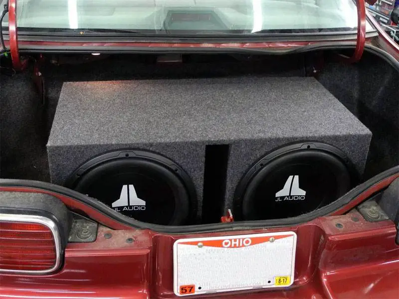
Even though massive audio systems can increase volume, they swallow up cargo space. While quality speakers enhance your ride’s acoustics, some DIY setups go too far.
Turning your entire trunk into a bass box might impress some, but it destroys utility. With barely room for a gym bag, form has gone too far before function. Even though wall-shaking decibels and ground-vibrating bass seem cool at first, you’ll probably regret losing practicality and your neighbors will hate you.
#7 – Empty Roof Boxes Just for Show
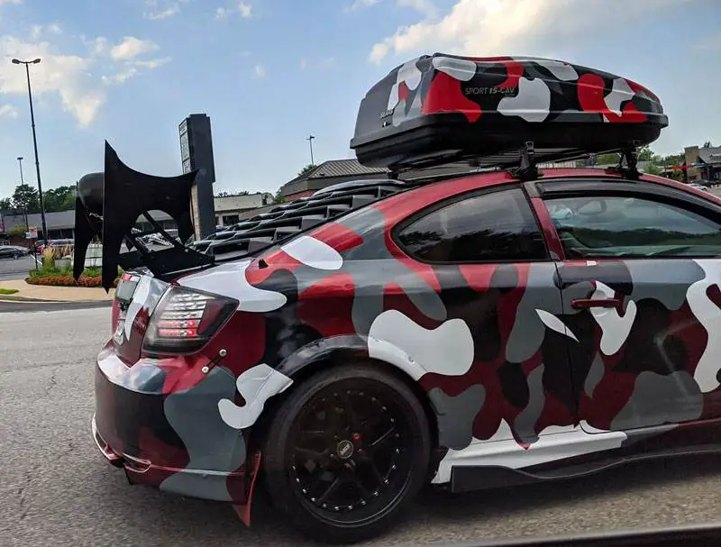
Slapping a cargo box on the roof just for the look hampers MPG without any added utility. While storage boxes increase carrying capacity if used correctly, empty shells just add unnecessary drag.
Beyond wasting fuel to carry useless air, they invite sharp eyes to laugh when spotting their hollow hype. Roof storage should showcase real capabilities, not fabricate them through visual trickery. Leave the roof rack off until it’s ready for real action.
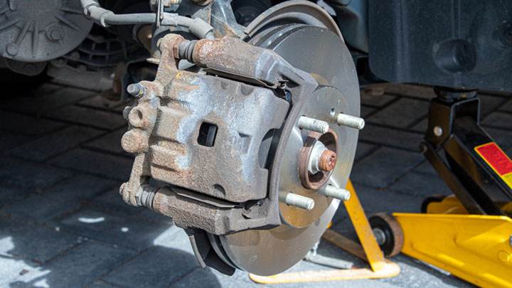
#8 – Fake Brake Caliper Covers
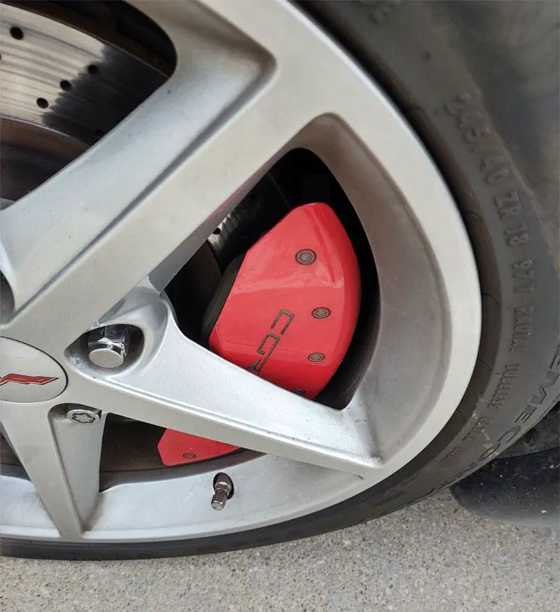
Snapping decorative covers onto stock brake calipers strives to fake performance credibility. While upgraded calipers can improve braking, fake ones are all show. These slip-on shrouds aim to mimic the look of real big brake kits, but their pointless style fools no one.
Beyond useless aesthetics, they can reduce brake system cooling and even fall off while driving. Don’t pay for imitations that hinder your brakes. If upgraded stoppers are just for looks, consider using that money for real brake upgrades instead of fake caliper covers.
#9 – Spiked Lug Nuts

Hollow spiked lug nuts try to look mean without the messy drawbacks. But these faux-deadly wheel nut covers offer no benefit beyond questionable style points. While posing no puncture risk, they can still loosen and cause collateral damage to brakes and suspension.
And their imposing image invites similar legal pressure in some areas. If you want style points with your wheels, invest in real alloys, not plastic spikes. Leave the hostile lug nut look to movie villain cars, not your daily driver.
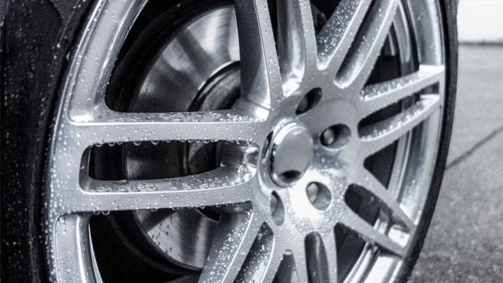
#10 – Massive Chrome Wheels
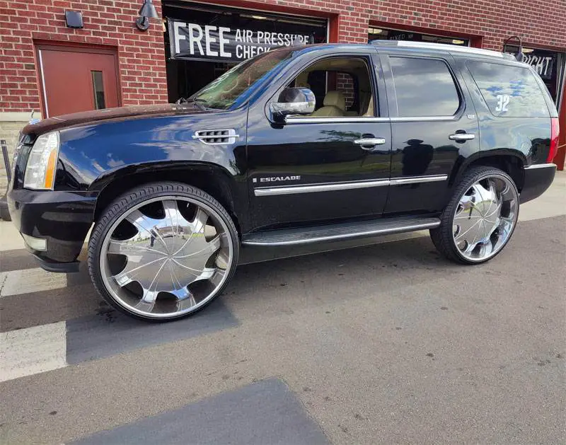
Bigger isn’t always better when it comes to chrome wheels. While larger diameter wheels can enhance performance if properly fitted, some go overboard with giant chrome rollers that look completely disproportionate. Oversized chrome wheels might shine, but they scream poor taste when they overshadow the rubber.
Beyond appearance, oversized wheels can reduce ride comfort, handling, and even fuel economy. Big shiny wheels also attract thieves. Instead of obnoxious huge chromes, invest those funds in appropriately sized lightweight alloys that actually improve your drive.
#11 – Non-Functional Hood Scoops

Though meant to look aerodynamic, non-functional hood scoops are all show and useless. These cosmetic additions try to mimic the appearance of real ram air intakes that force-feed the engine air. But without actually connecting to the air intake system, they serve no purpose beyond questionable style.
Plastic stick-on scoops only trigger laughter, not power. If the goal is improving engine breathing, save your money for legitimate performance upgrades that increase power. Otherwise, you end up with worthless fake vents that only drain your wallet.
#12 – Poorly Done Matte Paint Jobs

Even though matte paint can look amazing when done right, sloppy applications prove problematic. Achieving a smooth, flat finish requires meticulous prep and spray technique. But some overambitious DIYers end up with blotchy, uneven layers from a rattle can.
Beyond horrible aesthetics, defective matte paint lacks durability, causing damage from swirls, UV rays, and scratches. Spare your ride from being an eyesore and your wallet from redos. Stick to professionally applied paint or quality wraps instead of trying cheap matte.
#13 – Fake Vents
Fake vents are arguably one of the dumbest car mods. They strive to create a racy look, but these faux body additions are useless beyond appearances.
Unlike functional vents that actually ventilate engine compartments or wheel wells, fake vents are simply bolt-on posers. Without real openings or ducts, they serve no purpose other than questionable style attempts.
Besides looking obviously fake due to using plastic covers instead of cutting metal, they seem tacky and might even reduce aerodynamics. Don’t pay for useless embellishments that mimic real vents. If your fenders need venting, do it right or just leave them be.
#14 – Fake Exhaust Tips That Don’t Connect to the Exhaust

Chrome fake exhaust tips are harsh but literally exhaust no one. These slip-on shrouds only mimic the appearance of real exhaust pipes though not actually connected to the exhaust system. Without engine gases flowing through them, they’re all shine with no sting.
Beyond useless aesthetics, they can muffle actual exhaust noise, potentially signaling issues. Don’t pay for non-functional decor that masks your vehicle’s true voice. If your car needs more aggressive exhausts, go for real cat-back upgrades. Otherwise, fake tips will detect your fake status.
#15 – Spinner Rims
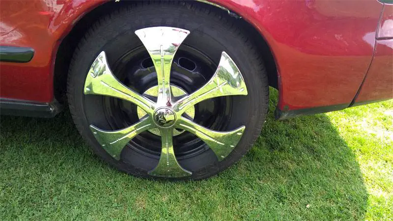
Wheels that keep spinning in place might dizzy spectators, but spinner rims serve no purpose in practice. These motorized kits allow stationary wheels to rotate around a fixed hub. Initially meant to keep chrome rims clean while parked, spinners have long outlived their limited utility.
Besides being outdated, they reduce real-world functionality by adding weight and complexity while hindering acceleration. Unless you want to perpetuate 2000s car culture nostalgia, leave spinners in the bling era.
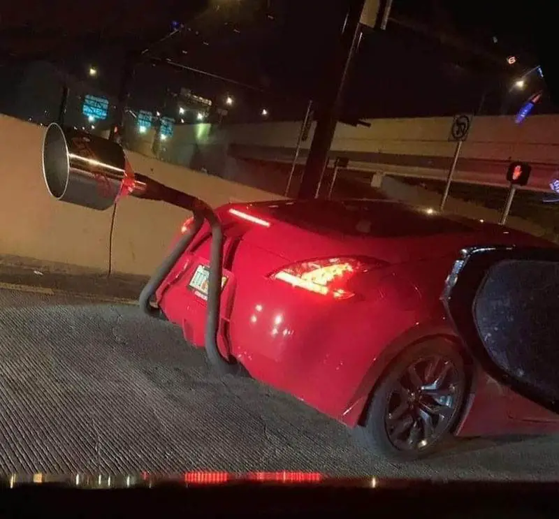
#16 – Huge Exhaust Tips
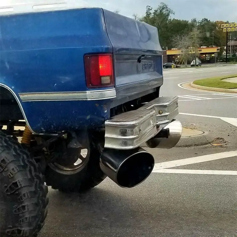
Oversized exhaust tips strive to visually amplify engine power but often backfire. Massive exhaust outlets seem tough but often belong to anemic engines rather than high-horsepower monsters.
Like fake chrome tips, these coffee-can-sized shrouds often don’t connect to real exhaust pipes. They muffle the true engine sound while aiming to visually deceive. Big tips don’t equal big power. Only significant engine builds deserve large-sized exhausts. Go big under the hood before getting loud at the tail.
#17 – Squatted Trucks
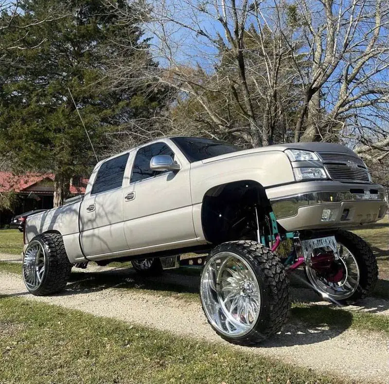
Squatted trucks for the “Carolina Squat” or “Cali Lean” are a trend that deserves the boot. This stance lifts the front while lowering the rear, creating an awkward nose-high appearance.
Besides looking broken, it also harms performance by compromising weight distribution and suspension geometry. Plus, driver visibility is severely reduced. Due to the danger, many states have banned squatted trucks.
#18 – Exhaust Whistle Tip
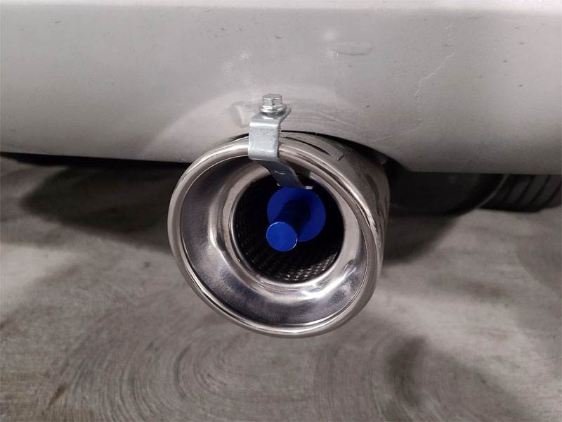
Whistle tip exhausts aim to mimic turbos but usually just make noise in neighborhoods. These clamp-on devices fit existing exhaust outlets to add a high-pitched whistle during acceleration. But their auditory assault annoys more than it increases performance.
Besides irritating everyone within earshot, whistles can signal problematic backpressure from clogged exhausts.
#19 – Bullet Hole Decals

Don’t shoot your vehicle’s style in the foot with fake bullet impacts. These vinyl decals aim for danger but misfire horribly. Beyond questionable taste of fake gunfire, adhesive perforations devalue your vehicle’s appearance instead of enhancing its edginess. And ironically, real bullet damage would likely risk destroying your car rather than cleanly piercing it.
If your goal is an urban, authentic look, invest in quality wrap or paint work done by a skilled shop. Otherwise, ditch the tacky cosplay and aim for real automotive aggression through performance upgrades.
#20 – Obnoxiously Loud Mufflers and Exhausts
Exhaust systems that shatter eardrums might seem cool but are more nuisance than upgrade. While properly tuned exhausts enhance performance and responsiveness, overly loud setups push noise pollution too far.
Beyond annoying entire neighborhoods, extremely loud mufflers often backfire, signaling engine issues needing tuning, not deafening decibels. On top of that, your chances of receiving heavy fines and citations for violating local noise ordinances increase significantly.
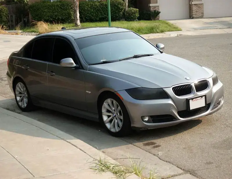
#21 – Window Tint That’s Too Dark

While light to moderate tint levels are a great way to enhance your vehicle’s appearance, overly dark windows increase risks as well as style. Legal limits exist for good reason: excessive tint dangerously reduces visibility, especially at night. But even when accepted, blackout tint screams overkill rather than tasteful accent.
Beyond endangering safety for imagined menace, complete light blocking ruins your vehicle’s exterior aesthetics. Consider balancing slightly darker rear tints with clearer fronts for enhanced style without driving blind.
#22 – Distracting Interior LED Lighting

Shift Solenoids (Operation and Failure Symptoms)
To understand shift solenoid symptoms, it’s important to understand why and how automatic transmissions shifted BEFORE there were solenoids, and why solenoids were added to begin with.
How Planetary Gears Work
Transmissions and transaxles that shift automatically (CVT units not included) have one or more planetary gearsets at the heart of the unit. These gearsets, along with driving and holding elements such as brakes and clutches, provide the different gear ranges, including reverse.
A simple planetary gearset consists of a sun gear, a planet carrier with several small planet gears that rotate around that sun gear, and a ring gear that surrounds the outside of the planet gears.
If you hold the planet carrier and drive the sun gear, the ring gear is driven in the opposite direction. That’s reverse.
Holding the sun gear and driving the ring gear drives the planet carrier to provide a gear reduction ratio, and holding the ring gear while driving the planet carrier spins the sun gear as the output to provide a different gear reduction ratio, and so on.
Power from the engine is transferred via the torque converter, which has an impeller integrated into the torque converter shell and a turbine with matching blades attached to the shaft that drives the guts of the transmission.
Any part of the planetary gearset can be held or driven. Clutches inside rotating drums are applied hydraulically by a piston inside the drum. “Brake clutch” packs or static bands attached to the outside of the transmission and applied by hydraulic pistons act as “holding” elements.
There are also one-way clutches that are applied mechanically by the direction of the rotating elements.
The Hydraulics of a Transmission
The hydraulic element of a transmission starts with the suction of fluid from the pan through the filter to the pump, which is driven by the outer shell of the torque converter. This shell is bolted to the engine’s “flexplate,” which is, at its center, bolted to the crankshaft.
It’s called a “flexplate” because as pressure builds in the torque converter, its shell expands, and since this shell is bolted to the outer edges of the flexplate, this plate must flex with the torque converter’s expansion. This is why automatic transmission flexplates sometimes crack around the center.
The hydraulic pressure created by the pump fills the torque converter and is available to the “valve body” as “line pressure.” This valve body is usually made of aluminum and is bolted to the transmission case with a plate sandwiched between two gaskets featuring many small holes.
The valve body is machined with a complex set of internal passages featuring spool valves and springs designed to direct hydraulic pressure to the various driving or holding elements that interact with the planetary gearset(s) that provide the different gear ranges.
Keep that thought – we’ll get to the solenoids in a minute.
How Older Transmissions Shifted
A “governor” with an internal spool valve was originally designed to spin faster as vehicle speed increased, and this governor would actuate its spool valve using centrifugal force.
As the spool valve inside the governor changes position with increasing vehicle speed, the fluid pressure passing through the governor is sent to other spool valves inside the valve body, moving them against spring pressure and redirecting fluid to the driving or holding elements.
It is necessary to hold each gear longer when the transmission shifts under heavy acceleration or when the vehicle is pulling a heavy load. This requires another pressure channel that opposes the governor pressure. This pressure is called “throttle valve” pressure.
On many older transmissions, there is a “modulator” valve with a movable core attached to an internal vacuum diaphragm inside the valve. The core moves a simple spring-loaded spool valve in the transmission.
The vacuum feeding this modulator valve comes directly from the intake manifold. When the engine is under load, vacuum decreases, the valve core moves its spool valve in the transmission to fight against the governor pressure.
When throttle valve pressure is high, governor pressure cannot cause the next shift in the sequence until vehicle speed (via the governor) increases governor pressure enough to overcome the throttle pressure, forcing the shift to occur, only later than it would have with lower throttle pressure.
Almost all transmissions began moving away from vacuum modulators to using throttle position (via a linkage or cable) to control throttle valve pressure. Chrysler transmissions never used vacuum modulators, unlike most other platforms.
Solenoids and Failure Symptoms
The first transmission solenoids were designed to control the “torque converter clutch,” a feature that began appearing in the late 1970s aimed at increasing fuel economy.
Most transmissions had 3 speeds and “Overdrive.” In third gear, the Torque Converter Clutch (TCC) would lock the torque converter shell to the turbine, causing a direct connection between the engine and the turbine shaft. When you press the brake, the torque converter clutch releases.
When the engine is cold, some vehicles do not allow torque converter lockup, as it generates heat while shearing the fluid when the TCC is unlocked, and transmission fluid needs to warm up quickly for optimal transmission operation.
These TCC solenoids can stick, keeping the torque converter engaged when the vehicle comes to a stop, causing the engine to stall. This is the first symptom we’ll mention that can be caused by a faulty solenoid.
If the solenoid fails to lock the TCC, fuel economy will suffer and the driver might not even realize the TCC isn’t locking, unless they are diligent about monitoring the tachometer.
Solenoids and Vehicle Computers
As computers became commonplace on vehicles in the late 1970s and early 1980s, engineers began giving computers control over more and more components.
Even though the valve body still functioned the same way, computer inputs and outputs were added. Pressure switches reported fluid pressure in various parts of the valve body. These early switches were simple on/off switches but were quickly replaced by one or more transducers indicating pressure.
Throttle valve pressure and what was once governor pressure both became elements of the computer-controlled transmission through the pulsed application of a special solenoid. Shift solenoids could be applied to force an increase in fluid pressure in certain parts of the valve body.
Engine load, vehicle speed, transmission input and output shaft speeds, and throttle position suddenly became the data that determined transmission pressures, shift points, and even the feel and quality of the shift. Many transmissions momentarily “decouple” the engine at the moment the transmission shifts to soften the shift feel.
Some Asian vehicles used “fuzzy logic” to prevent the transmission from downshifting while climbing shallow grades with cruise control activated. Performance packages began appearing with switches on the dashboard or shifter to alter the shift feel for those who liked sharp, hard shifts between gears.
Shift Solenoid Operation and Problems
Different transmissions have a different number of solenoids, and they don’t always operate in the order we might think. Sequential thinkers might logically believe that if a transmission has Solenoid A, Solenoid B, and Solenoid C, then Solenoid A would trigger the 1-2 shift, Solenoid B the 2-3 shift, and Solenoid C would trigger the 3-4 shift.
That’s not how it works.
You can look at a simple shift solenoid chart and see how complicated solenoid operation is between gears:
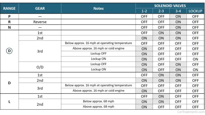
When solenoids fail, it depends on WHICH solenoid fails as to what results. A single shift solenoid can fail and affect multiple gear ranges (see the chart above). And not all symptoms are solenoid-related.
Solenoid-related DTCs will indicate the solenoid’s electrical circuit or a condition where there is nothing wrong with the circuit but the PCM or TCM has commanded the solenoid to act but determines from the input and output speed sensors that the commanded shift did not occur as commanded. This is classified as a “performance fault.”
Typically, when a solenoid fails, you will notice a difference in the feel or quality of the shift. The transmission might skip a gear, shift harshly, etc.
If power is lost to the transmission solenoids on newer vehicles, the pressure control solenoid will default to high pressure to prevent the clutches from slipping and destroying themselves, and the transmission will default to a higher gear than first gear.
But on earlier transmissions, the transmission solenoids were powered by a fuse, and if that fuse is removed or blows for any reason, the transmission will take off in first gear and never shift.
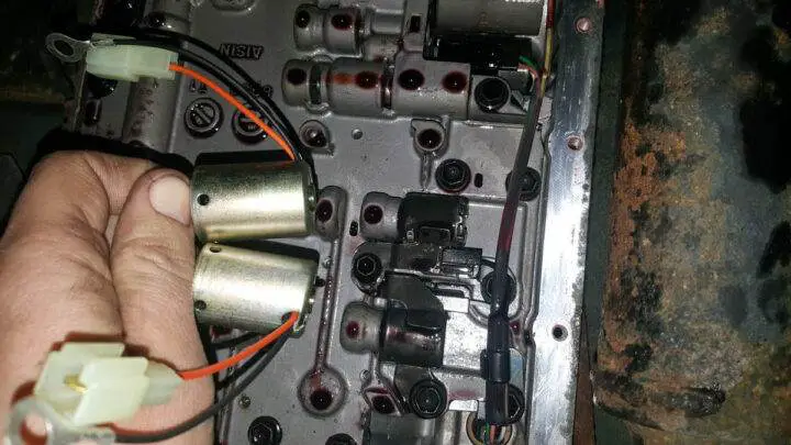
Where Are the Shift Solenoids Located?
Solenoids were initially mounted on the valve body as separate components, and most transmission shops would replace all solenoids when rebuilding a transmission (this is a good practice) to prevent solenoids from causing issues, as they often do.
Many transmissions and transaxles still have shift solenoids mounted directly on the valve body, but they are often sold in sets.
But on newer transmissions, solenoids are usually contained in a single “solenoid pack” that houses all the solenoids. This solenoid pack on some Chrysler transaxles is external and can be replaced without even removing the transmission oil pan, but most solenoid packs require draining the fluid to replace the solenoid pack, and in some cases, programming or a learning procedure may be required.
Some Honda transaxles typically have individual solenoids mounted externally.
Asian transaxles (like Nissans) typically ground their transmission solenoids and switch power to the solenoid from the PCM/TCM, but most other platforms power the solenoids whenever the key is on and control them by switching the ground.

Tips to prevent a shady mechanic from taking advantage of you
Are you afraid that your mechanic is trying to scam you? Perhaps they speak gibberish or use fear as a tactic to force you into unnecessary work so they can charge you more.
Although most repair shops are ethical, there are bad apples who try to take advantage of vulnerable people or those lacking automotive knowledge.
Here are 20 tips to avoid dishonest mechanics and car scams in general.
#1 – Look for Reviews
One undeniable advantage of living in the technical age is that reviews for most businesses are now easily accessible online. Websites like Yelp and Google My Business allow users to access endless reviews for any establishment with a simple click of a mouse or tap of a finger.
Before going to an auto repair shop or a dealership’s service department, browse through a number of these reviews, checking for any indication of questionable business practices.
#2 – Know Your Rights as a Consumer

It’s important to understand that you have certain rights as a consumer. You have the right to refuse any service that you do not deem necessary or prefer to opt out of. A shop cannot perform any unauthorized work or work that you do not agree to have done.
Avoid falling for questionable language such as “you must” or “it’s mandatory.” All services to be performed should be explained to you in detail before work begins.
#3 – Call a Friend
If you don’t feel comfortable assessing the truth of what a mechanic is telling you on your own, ask a friend or family member who is more knowledgeable about mechanics to accompany you.
This person can help you separate fact from fiction, ensuring that you are not misled, misquoted, or misrepresented.
#4 – Ask to See the Faulty Components
If you are told that a certain component has failed on your vehicle, ask to be shown the component in question and have it explained to you exactly how that component failed.
This is especially true in situations where news of this nature is unexpected.
#5 – Mark Filters in an Identifiable Way
A great way to ensure the honesty of quick lube shops is to mark your vehicle’s filters (oil filter, air filter, cabin air filter) in an identifiable way with a permanent marker.
You can then inspect these filters once the maintenance is completed, to see if they were actually changed or if your vehicle’s old pre-sale filters are still installed.
One of the most common scams is when a dishonest technician shows you a dirty engine air filter or cabin air filter from another car while you are in the waiting area, when they haven’t even inspected your car’s filter.
They are counting on the fact that you have never inspected your filter or plan to do so once you leave the shop.
#6 – Ask to Be Contacted Before Any Additional Work Is Done
If you drop your vehicle off at a shop for repair, ask to be contacted before any additional work is performed.
This not only ensures that no other work is done, outside of what was proposed, but also allows you to request an “upfront” quote for any work recommended as an additional service.
#7 – Get Multiple Quotes for Larger Repairs
When anticipating the need for substantial work, be sure to get quotes from multiple shops. Any quote that is odd compared to all the others is likely a scam, at least to some extent.
Some shops significantly mark up parts to increase their profits, making projects of this nature easily detectable when receiving many quotes.
#8 – Ask for Detailed Receipts
Before agreeing to any repair, inform the service writer of a shop that you will need a detailed receipt. If they ask why, say it’s for business purposes.
In at least some cases, this will deter questionable mechanics from inflating costs or imposing unnecessary fees, as they will be easier to detect and challenge.
#9 – Watch When Possible

Many shops leave their doors open throughout the workday during the warm season. Use this to your advantage by staying within sight of the technician working on your vehicle.
Pretend to step out for some air or to take a phone call. No matter what you do outside, as long as the technician in question feels they are being observed.
#10 – Always Get a Written Warranty
Whenever you are assured that a particular repair will be covered by a parts/service warranty, make sure all such claims are provided in writing.
Nothing is worse than being forced to resort to such a warranty, only to be told that you were never covered under any warranty terms.
#11 – Know Your Vehicle’s Maintenance Intervals
Don’t be pressured into buying additional services at a quick lube shop simply because you are told that a particular service is recommended for your vehicle’s current mileage.
Your vehicle manufacturer’s recommendations should be the only true source of guidance on these matters. Learn these recommended maintenance intervals (which you can find in your owner’s manual) and stick to them.
#12 – Beware of Scare Tactics
Most automotive professionals are perfectly capable of conveying the importance of a repair without trying to scare customers into an impulse purchase.
If a mechanic tries to scare you into a repair by telling you that your engine “will blow up tomorrow” or that you risk having an accident, their motives are often questionable.
The worst of the worst is when unethical mechanics try to take advantage of elderly people using alarmist tactics.
#13 – Never Agree to Uncapped Diagnostic Fees

Some shops have a habit of charging hourly diagnostic fees that are in no way capped or limited. This is almost always a bad deal for the consumer, as it gives a shop a blank check that they can write for whatever amount they deem appropriate.
If a particular job cannot be quoted initially, or after previously agreed-upon diagnostic fees, take your business elsewhere.
Even better, get a basic OBD2 scanner so you can easily scan your vehicle for trouble codes when a Check Engine light comes on. You will now know what is wrong with your car.
#14 – Ask to Speak to the Technician
In some shops, service writers receive a commission. Therefore, it is not uncommon for service writers to push repairs or services with a sense of urgency that could otherwise wait.
If you think this might be the case, ask to speak to the technician working on your vehicle. In most reputable shops, a technician will be much less likely to perform unnecessary repairs than an unscrupulous service writer.
#15 – Minimize Your Lack of Automotive Knowledge
If you don’t know much about vehicles in general, keep that information to yourself.
While it’s fine to ask any necessary questions, openly discussing that you know nothing about your vehicle serves as a sort of dinner bell for mechanics with questionable motives. After all, a shady mechanic’s worst nightmare is having an informed car owner.
#16 – If You Have Questions, Ask Them
If you are unsure about what a mechanic or service writer is telling you, ask as many questions as come to mind. Those with good intentions should be more than happy to answer all your questions.
On the other hand, technicians or service writers who repeatedly avoid questions are likely suspect.
#17 – Research Parts Costs
If you take your vehicle to a shop for a scheduled repair, research the cost of the parts associated with those repairs in advance.
To see if you are being taken advantage of, calculate a 10 to 20 percent markup on the average cost of the component to be replaced, then compare that figure to the one quoted as the anticipated parts cost.
If the quoted number far exceeds the pre-researched cost, ask for additional explanation.
#18 – Inquire About Labor Rates Upfront
All shops have designated labor rates on which they base the cost of their work. This rate is usually posted somewhere within the service advisor department or the shop’s reception area itself.
Most reputable shops will be happy to provide their hourly labor rate to any potential customer. If a shop cannot or will not provide this information, there is probably a reason.
#19 – Conduct Your Own Research
Sometimes it is helpful to investigate the problem your vehicle is experiencing before taking it to the garage. Even if you might not be able to fully diagnose the issue in question, you will at least be better able to determine if what you are told at the repair shop actually makes sense.
This essentially prevents you from flying blind and being forced to accept whatever you are told on a whim.
#20 – Trust Your Instinct
As with anything, your initial gut feeling about a particular shop’s business dealings has merit. If something just doesn’t feel right, there is probably a good reason.
Keep this in mind and avoid overriding your instinct at all costs. Your vehicle is an investment that deserves to be protected and should always be treated as such.
Symptoms of a Faulty Distributor
Is your vehicle currently operating with far from optimal efficiency, or worse yet, not running at all? If so, distributor-related issues might be the cause.
This essential component might be the most valuable of all modern automotive ignition systems, but it can be the source of numerous difficulties when it fails.
The following guide will detail the various symptoms associated with a distributor failure, while also addressing a number of the most common distributor-related symptoms.
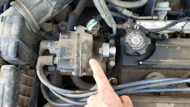
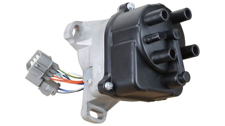
What is a Distributor?
An automotive distributor is perhaps best described as an electromechanical device designed to deliver a spark to each respective cylinder, in a precise manner. This spark originates from an engine’s coil, before being “distributed” cylinder by cylinder.
The distributor itself is mechanically synchronized with the engine on which it is mounted, via a specialized drive gear. This drive gear is located at the end of a rotating shaft equipped with a replaceable electrical contact called a rotor button at its opposite end.
The aforementioned rotor button is powered by coil-induced energy, which is then distributed to the individual contacts mounted on the cap for each respective cylinder in a precisely timed manner.
Essentially, a distributor’s rotor button serves as a rotating electrical contact that powers each spark plug wire, via intermittent continuity with individual electrodes mounted on the cap.
When the finger of a rotor button touches the electrode of a specific cylinder, energy is discharged via the corresponding spark plug wire to that cylinder’s spark plug.
Symptoms of a Bad Distributor
The failure or impending failure of a vehicle’s distributor is often attributed to a multitude of secondary symptoms, some of which tend to be rather severe in nature. Recognizing these signs often proves essential when attempting to expedite replacement and, ultimately, repair.
Here are some of the most common symptoms associated with a faulty distributor.
#1 – Check Engine Light Illuminated
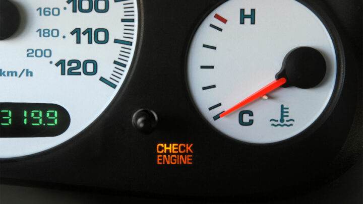
>A distributor failure will almost always cause a vehicle’s Check Engine Light to illuminate. This typically occurs when multiple misfire codes are logged and stored.
The Check Engine Light itself will remain illuminated as long as these codes remain active.
#2 – Repeated Stalling
When a distributor fails, ignition timing is often lost. This creates a condition in which efficient engine operation is impossible to achieve. This will typically result in repeated stalling if the engine in question is running at all.
#3 – Failure to Start

Just as described in the scenario above, a faulty distributor can quickly lead to a scenario where an engine fails to start or continue running after its initial combustion cycles. Starting attempts will typically be accompanied by a volley of misfires.
#4 – Constant Misfires/Backfires
If an engine’s distributor is no longer able to maintain correct ignition timing, constant misfires and backfires are to be expected. This will generally continue until the engine itself is no longer able to keep turning.
Significant vibration may also be felt, in most cases, when such symptoms are present.
#5 – Squealing Noises

Although rare, the internal bearings of a distributor can fail in service. This leads to a distinctly audible squealing noise that can often be heard during normal engine operation. This sound is often heard more pronounced during startups.
Distributor Replacement Cost
Best Places to Order Parts?
The cost of distributor replacement often varies from one vehicle model to another, due to variations in parts costs and labor requirements to perform such a repair.
However, you can generally expect to pay between $450 and $800 to have your vehicle’s distributor replaced, with the vast majority of this cost being attributed to the parts cost.
Repair
On the other hand, you can maintain a viable distributor for much less. This involves replacing a worn or damaged rotor button and a worn or cracked distributor cap. This repair can often be performed for less than $50 in parts and about $100 in labor fees.
Distributor vs Distributor Cap
It is not uncommon to hear the terms “distributor” and “distributor cap” used interchangeably. However, these two components are not actually one and the same.
Specifically, a distributor cap is an individual part of the entire distributor assembly as a whole. The fact that a distributor will not function without a distributor cap, and a distributor cap would be useless without a distributor, perhaps best illustrates this concept.
The term “distributor” describes the drive assembly responsible for maintaining proper spark timing relative to base cam/crank timing. This assembly uses a coil (internal/external) and features a built-in timing advance mechanism.
Meanwhile, a “distributor cap” mounts on top of the distributor itself and features output contacts that allow power to be distributed to each respective spark plug wire.
FAQ
Do All Vehicles Have a Distributor?
The common automotive distributor is becoming less and less common over time. The vast majority of recent vehicles are now equipped with individual coils for each respective cylinder, thereby eliminating the need for spark distribution via a traditional distributor.
The latest distributorless ignition systems power these independent coils with high-voltage control modules, designed to provide a precisely timed spark.
That being said, there are still many vehicles on the road today equipped with distributors. As a result, distributor-related failures remain a consideration, particularly in the aging sector of vehicles in service.
However, it is reasonable to assume that a time will soon come when distributors become completely obsolete, much like the old points/condenser type distributors of years past.
What Causes a Distributor to Fail?
A distributor can fail for several reasons. Among the most significant of these causes are the eventual wear of components and bearings of the basic drive assembly, as well as internal arcing induced by carbon buildup.
Individual distributor-related components can also fail with age. Distributor caps can crack, allowing moisture intrusion or causing electrode erosion. Similarly, rotor buttons can degrade over time, or even break completely.
How Many Miles Do Distributors Last?
An average automotive distributor can be expected to last for the entire lifespan of the vehicle it is equipped on. However, as with any component, unexpected distributor failure can and sometimes does occur.
On the other hand, several distributor-related components are considered wear items, thus requiring periodic replacement. This notably includes a distributor’s cap and rotor button, which typically need replacement every 20,000 to 25,000 miles.
Can a Car Run Without a Distributor?
An engine can certainly run without a distributor. Most recent vehicles are now designed to forgo the use of a traditional distributor, in favor of a fully distributorless ignition system. In such cases, individual coils or coil packs are fired via a computer-controlled driver.
However, the integrity of the distributor remains a deciding factor for vehicles designed with a traditional distributor-based ignition system. Without a viable distributor, such a system is incapable of generating a spark at the correct time.
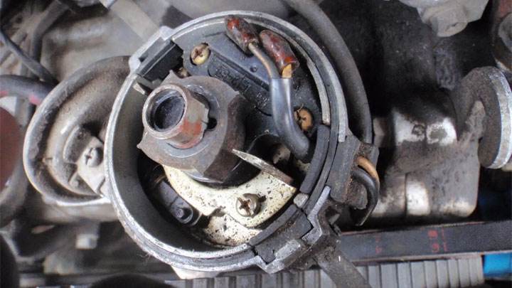
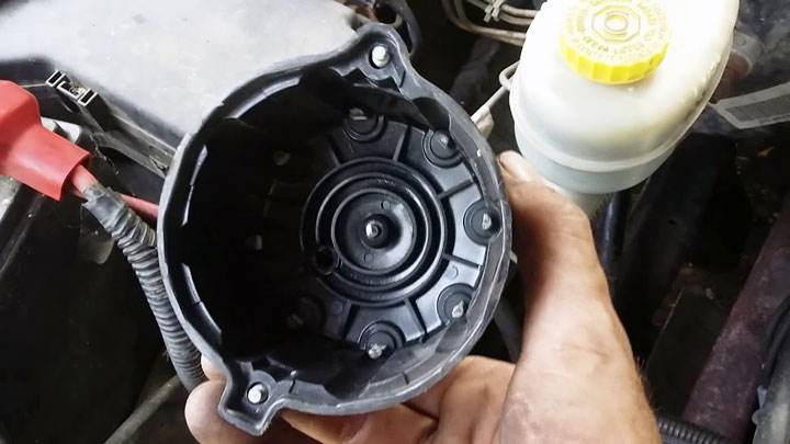
Can You Tell a Distributor is Bad Just by Looking at It?
It can be quite difficult to condemn a distributor based solely on a visual inspection. Unless visible wobble of the distributor body itself is observed or excessive play in a distributor’s drive gear can be verified, you will struggle to spot an impending failure.
On the other hand, you can condemn individual distributor-related components, such as a rotor button or distributor cap, through simple visual inspection.
Where Should the Distributor Rotor Point?
A distributor’s rotor should always point towards the individual electrode mounted on the cap that corresponds to the next cylinder scheduled to reach its top dead center position. This places increased importance on the correct timing of any distributor to be installed.
If you are only replacing the distributor’s rotor button itself, timing will pose little issue, as most rotor buttons feature a specially indexed tab. This prevents the rotor button from being installed incorrectly.

Brake judder: why does my car vibrate when braking
Do you feel your brake pedal pulsating and vibrating when slowing down? Don’t panic, but don’t ignore it either. The unsettling sensation known as brake shudder likely stems from various causes requiring repairs, but not from imminent brake failure.
However, identifying the root cause is essential to restoring smooth and safe braking. Continue reading to discover the causes of brake shudder, how to fix it, and whether your driving habits allow brake shudder to develop.
What is Brake Shudder?
Brake shudder is perhaps best described as a shaking sensation felt through the steering wheel and front suspension of a vehicle whenever the brake pedal is pressed. In many cases, it feels as if these vibrations occur at different frequencies during slow-speed braking, as opposed to high-speed braking.
The way brake shudder is felt largely depends on the root cause of the condition itself. This comes from the fact that not all brake shudders are caused by the same underlying problem. Even though many would be inclined to believe that any brake shudder is directly related to the condition of a vehicle’s basic brakes, this is not always the case.
Understanding the above principle also helps when attempting to correct brake shudder as a whole. Since not all cases of brake shudder are identical, there is no one-size-fits-all approach to solving this problem. A thorough diagnosis of the current condition is the only real way to avoid unnecessarily replacing otherwise fully repairable components.
Common Causes of Brake Shudder
Brake shudder can be caused by a number of underlying issues, some of which are much harder to isolate than others. Those familiar with the different causes of brake shudder are often able to speed up their repair.
Here are some of the most common reasons why you experience brake shudder.
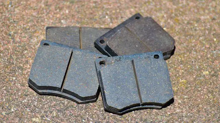
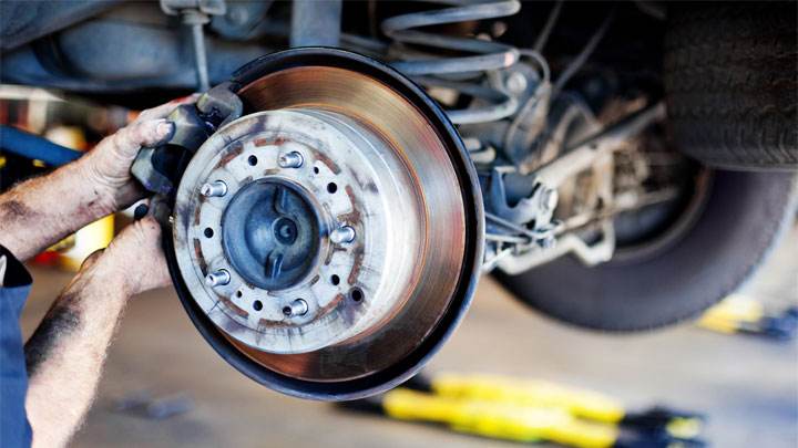
#1 – Warped Brake Rotors and/or Worn Brake Pads

Most often, brake shudder can be attributed to a combination of worn brake pads and warped brake rotors.
When a vehicle’s rotors and pads warp, an otherwise smooth friction surface is compromised. These irregularities then result in a persistent vibration or shudder when the brakes of the vehicle in question are applied.
#2 – Tire Imbalance
To minimize vibrations and maintain optimal performance, a vehicle’s wheels/tires must be balanced at specified intervals.
When wheels/tires are out of balance, a noticeable vibration can usually be felt at a defined speed. This can be felt in the same way a person would perceive brake shudder when the vehicle’s speed drops to a certain threshold during braking.
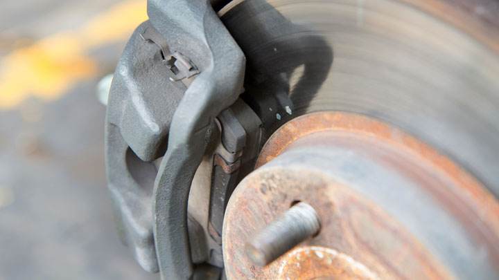
#3 – Sticking Brake Calipers
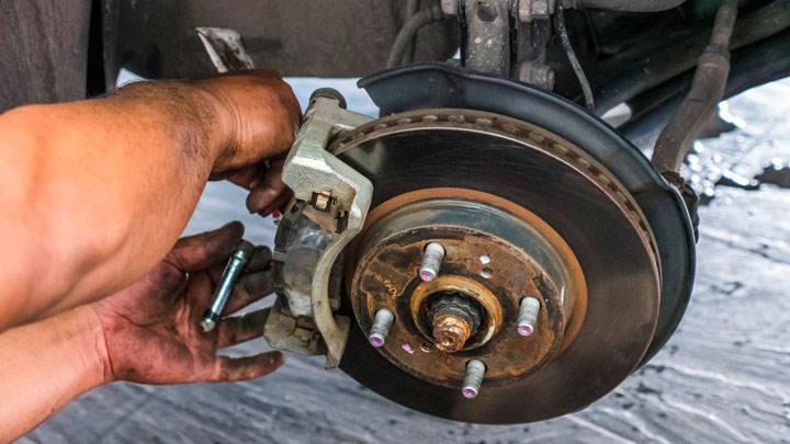
A vehicle’s brake calipers age and deteriorate over time, often leading to a condition known as “sticking.” When a brake caliper sticks, it becomes unable to release in response to the release of a vehicle’s brake pedal.
A seized brake caliper leads to uneven distribution of braking forces, often resulting in a perceptible shudder.
#4 – Poor Alignment
In a number of cases, brake shudder can be caused by irregular tire wear resulting from poor alignment. When the front of a vehicle is out of alignment, it often results in beveled or chopped tread.
The vibration resulting from this irregular wear is usually felt more intensely at a defined speed. This vibration manifests as brake shudder when braking reduces the vehicle’s speed into that specified range.
How to Fix Brake Shudder
Fixing brake shudder comes down to diagnosing the underlying condition causing the persistent vibration as a whole. In most cases, remedying the current situation will involve replacing a vehicle’s brake pads and rotors. This is especially true when brake shudder occurs at any speed.
If, after new pads and rotors, the brake shudder persists, attention will turn to tire/wheel imbalance, worn steering/suspension components, and/or poor alignment. At this point, a thorough inspection of all front-end components will be necessary.
This should be followed by an alignment of the front end of the vehicle in question and a four-wheel balance. Once these items are completed, a thorough road test should confirm the elimination of the previously persistent shudder.
Is Brake Shudder Dangerous to Drive With?
In itself, brake shudder is not too dangerous. However, this situation will only worsen over time, which could harm overall braking efficiency.
Therefore, you should not delay in resolving the issue in question, especially if you cannot be sure of the exact cause of the brake shudder you are experiencing.
In all cases, the root cause of your vehicle’s brake shudder should be carefully diagnosed and repaired as soon as possible. This will avoid any excessive risk and mitigate the risk of further deterioration of the foundation brakes.
If DIY repairs are not your forte, have a trusted mechanic or service center address the issue as soon as possible.
Can an Alignment Help?
Getting an alignment can indeed help with brake shudder as a whole, assuming, of course, that your vehicle’s brake shudder is primarily caused by poor alignment.
This is the case when irregular tire wear, caused by poor alignment, leads to a noticeable shudder when a vehicle reaches a certain speed. In such cases, an alignment followed by tire rotation is likely to eliminate the underlying shudder.
Can Bad Driving Habits Cause Brake Shudder?
Even if not always the case, bad driving habits can actually cause brake shudder in some instances and worsen it in others.
This is especially true in cases where drivers frequently panic-stop or heavily rely on their brakes repeatedly. This heavy brake usage can easily overheat key brake components, leading to rotor warping.
This, in turn, triggers a sort of vicious cycle, in which continued overly aggressive braking only further compromises a vehicle’s already warped rotors. As a result, brake shudder rapidly worsens to a much more noticeable degree than it otherwise would.

Assetto Corsa Rally Redefines Hardcore Racing Simulation
Assetto Corsa Rally Aims to Set New Standards in Racing Realism
The racing simulation landscape is about to experience a seismic shift with the upcoming release of Assetto Corsa Rally. Developed by Supernova Games Studios, this title brings together veteran talent from Codemasters, Milestone, and Slightly Mad Studios to create what promises to be the most authentic rally experience ever digitalized. Following recent industry shakeups, this project arrives as a beacon for simulation purists seeking uncompromising physics and true-to-life handling.
Technical Excellence Meets Rally Heritage
Built upon the legendary Assetto Corsa engine, the rally adaptation preserves the franchise’s renowned attention to detail while expanding into dynamic terrain and weather systems. The development team has implemented revolutionary surface deformation technology that tracks real-time changes to road conditions across various environments. From snow-packed Scandinavian trails to dusty Mediterranean mountain passes, each surface reacts uniquely to vehicle weight transfer and tire selection.
Comprehensive Career Mode and Vehicle Roster
Players will navigate through decades of rally history with meticulously recreated classic and modern vehicles. The career mode progresses from regional championships to full World Rally campaigns, featuring authentic stage designs and co-driver communication systems. Vehicle maintenance and setup become crucial elements as damage persists between stages, requiring strategic resource management throughout multi-event championships.
Next-Generation Damage and Physics Systems
The simulation introduces unprecedented mechanical fidelity where every component failure affects handling characteristics. Suspension damage alters weight distribution, transmission issues impact power delivery, and aerodynamic elements behave differently when compromised. This granular approach to vehicle dynamics ensures that every decision behind the wheel carries tangible consequences throughout each special stage.
With its November release approaching, Assetto Corsa Rally represents not just another racing game but a platform for continuous development. The commitment to hardcore simulation principles combined with accessibility through graduated difficulty settings creates an experience that will satisfy both newcomers and seasoned veterans of the genre.
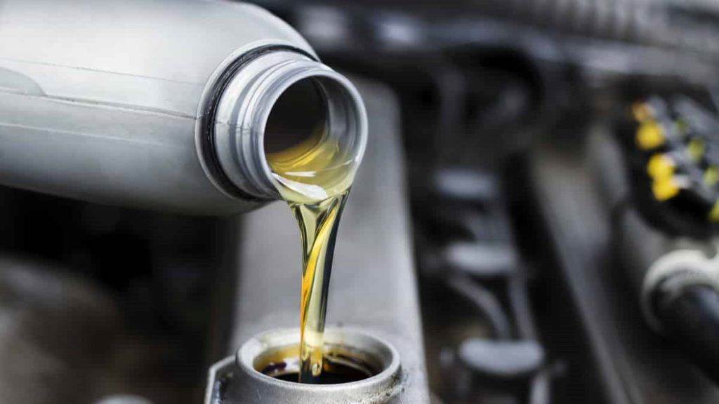
What are the differences between 0W-30, 5W-30, and 10W-30 engine oils?
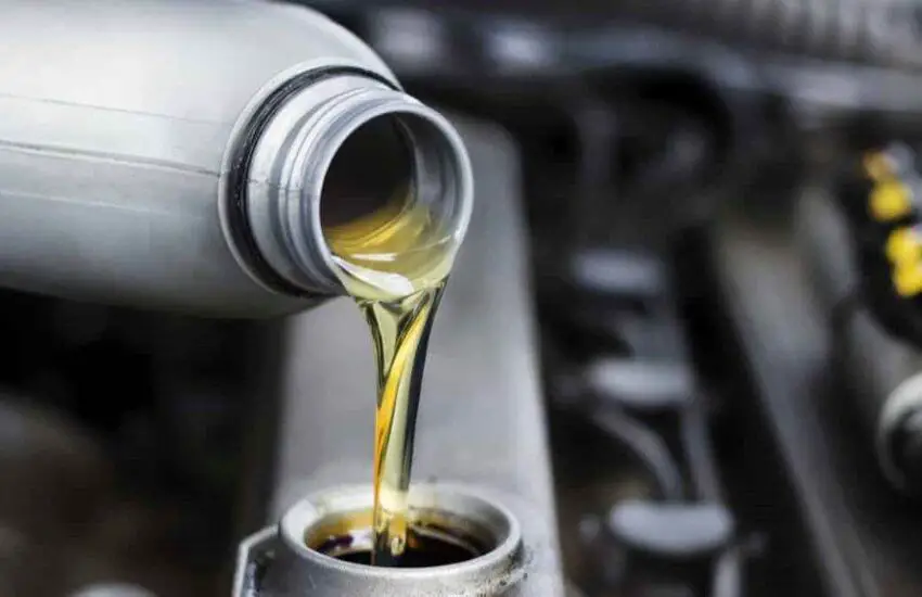
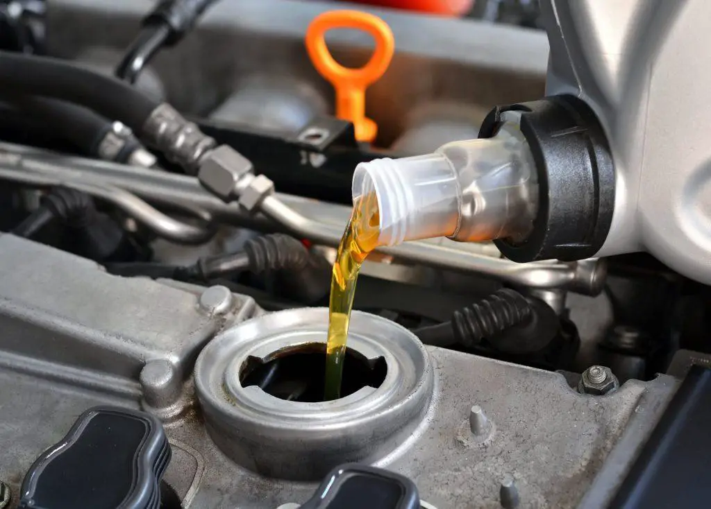
Engine oil is the lifeblood of your vehicle, as it keeps the car running at its maximum capacity. It cools, cleans, lubricates the moving parts of the car’s engine, and prevents metal parts from rubbing against each other.
Engine oil plays a crucial role in collecting dust and debris from the engine and keeping them in the oil filter. In short, your vehicle runs well with fresh engine oil making the parts function.
However, care must be taken in choosing the right engine oils so that their vehicle remains functional in the long term. Learn here the difference between the three types of engine oils, namely 0w-30, 5w-30, 10w-30!
Which engine oils are best for my car: 0W-30, 5W-30, or 10W-30?
Whether you’re looking to know about 0W30 versus 5W30 or any other engine oil, choosing the right viscosity for the engine makes all the difference in your car’s performance and maintenance.
It should not be forgotten that a car’s engine needs oil that can operate in all weather conditions. A 10W or 5W refers to the ease with which the oil will flow in winter.
However, it must be kept in mind that 10W thickens faster than 5W. The other number refers to the oil’s resistance to thinning under high-temperature conditions.
1. Overview of Car Engine Oil
The all-new engine oils, including 0W-30, 5W-30, and 10W-30, function like single-weight oils at your car’s full operating and warm-up temperature.
The majority of engines designed before Ford had 5W-20 oil specifications in 2001, and a 30 W weight was the ideal oil weight.
The next question that arose was whether to use 10W-30 or 5W-30 oil. It must be understood that before Group 2 hydrocracked oils gained popularity, 10W-30 oil was considered better due to the additives and viscosity index improvers.
It was commonly believed that viscosity index improving agents could not work effectively; 10-weight oil was a better choice than 5-weight oil.
Additives, not the oil, provide the required thickness for proper operating temperature viscosity.

2. The Difference
Before diving into the differences between 0W-30, 5W-30, and 10W-30, let’s decipher the code itself. The numbers preceding the “W” represent the oil’s viscosity at low temperature, with lower numbers indicating smoother flow.
The numbers after the “W” represent the oil’s viscosity at normal operating temperatures. Now let’s explore the unique attributes of each oil type.
Many car owners wonder which engine oil is the best. In short, many are confused about 5W30 versus 0W30. 10W-30 can be quickly obtained in conventional engine oil, as it is an economical oil option and not recommended by car user manuals.
However, if car owners end up purchasing it from a refinery, it will be hydrocracked. In short, the oil molecules would be of uniform size and require fewer viscosity improving agents.
5W-30 can be purchased as conventional, fully synthetic, or blended. It should be known that the fully synthetic would have fewer viscosity additives. The standard would have the maximum because synthetic molecules maintain their viscosity.
Here are some additional details on the difference between the 3 mentioned oil types.
- 0W-30: Cold Start Champion
The “0W” in 0W-30 means ultra-low viscosity, resulting in exceptional fluidity even in freezing conditions. This oil excels in protection against cold starts, ensuring your engine remains lubricated during icy mornings.
Ideal for frigid climates, 0W-30 offers rapid oil circulation, effectively reducing wear on vital engine components during startup. If you reside in a region where winters can be unforgiving, 0W-30 is your go-to choice.
- 5W-30: All-Season Performance
5W-30 strikes a delicate balance between cold resistance and high-temperature stability. Its low cold-weather viscosity ensures quick circulation during cold starts, thus preventing engine wear.
At high temperatures, 5W-30 maintains its viscosity, providing a consistent oil film for effective engine protection. This versatility makes it a preferred option for various driving conditions, from city commutes to highway cruising.
- 10W-30: Heat-Defying Guardian
With a slightly higher cold-weather viscosity than 5W-30, 10W-30 strengthens its game in the face of warmer climates. It forms a thicker protective film on engine components at higher temperatures, thus effectively protecting against engine stress and heat-induced wear.
This oil shines in regions with temperate climates, where temperature fluctuations are less extreme. Furthermore, older engines that benefit from a slightly thicker oil film find 10W-30 to be a reliable companion.
Making the Right Engine Oil Choice
Climate and Temperature Considerations
The choice between these oil types largely depends on your local climate. If you live in a region with harsh winters, 0W-30 oil ensures your engine’s vitality during cold starts. For more moderate climates, 5W-30 and 10W-30 offer commendable protection.
Addressing Your Vehicle’s Age and Condition
Consider your vehicle’s age and condition. Older engines, which may have undergone more wear, can benefit from the extra strength of 10W-30. In contrast, newer engines, especially those recommended by the manufacturer, tend to thrive with 5W-30.
Reflecting on Driving Habits
Your driving habits also influence the choice. If you frequently take short trips or navigate through traffic jams, opt for 0W-30 or 5W-30 to protect your engine from wear during frequent cold starts.

FAQ on 0W-30, 5W-30, 10W-30 Engine Oils
- Is it safe to switch between oils of different viscosity?
Switching to an oil with a similar viscosity rating is generally safe. However, consult your vehicle’s manual or a mechanic for specific recommendations.
- Can I use 10W-30 oil in winter?
Yes, you can use 10W-30 in winter, but it may not offer as effective cold start protection as 0W-30.
- Does using a higher viscosity oil increase fuel consumption?
Using a slightly higher viscosity oil, such as 10W-30, is unlikely to significantly impact fuel consumption.
- Can I use 5W-30 instead of 0W-30?
Yes, it is possible, especially if you live in a region with milder winters. 5W-30 still offers good cold start protection.
- How often should I change my engine oil?
Refer to your vehicle’s manual for oil change intervals. Modern synthetic oils typically last longer than conventional oils.
For more in-depth information and expert advice on choosing engine oil, feel free to consult automotive industry professionals.
Watch this video by Engineering Explained to learn more about the difference between synthetic and conventional engine oil!
Summary
Car owners can use an additive pack to blend oil and conventional oil to achieve the desired properties. This is one of the most important maintenance tips for your car’s engine.
So, if you are looking to know the difference between 0W-30, 5W-30, and 10W-30 engine oils, then we recommend referring to the information mentioned above.

Why does my car shake when I start it
Who hasn’t witnessed a shaky and trembling car at least once in their life? Almost every car owner has experienced a situation where they were so shaken that they felt like taking a ride in an amusement park. Moreover, you might be wondering: “why does my car shake when I start it?” Well, there is a reason why your car shakes every time you start it.
Understanding the real reasons for such behavior in your car can save you from being stranded in the middle of nowhere. So, in case your car shakes upon starting, it’s always better to know the reasons in advance to avoid any dilemmas later on.
Why Does My Car Shake When I Start It? Discovering the Reasons
There are several reasons that can make a car shake as soon as you start it. Why not explore them here?
1. Critical Engine Situation
The next time you think why does my car shake when I start it, it could be an engine issue, possibly. Problems in the engine can make the car shake. Yes, the engine compartment can emit the shaking or vibration. Perhaps it’s not receiving the proper amount of air, spark, or fuel to function correctly. Symptoms that may alert you to engine problems include shaking when accelerating the car or it may run fine for a while and then start to shake. When this happens, you’ll need to either buy a new spark plug or replace dirty filters with a new one.
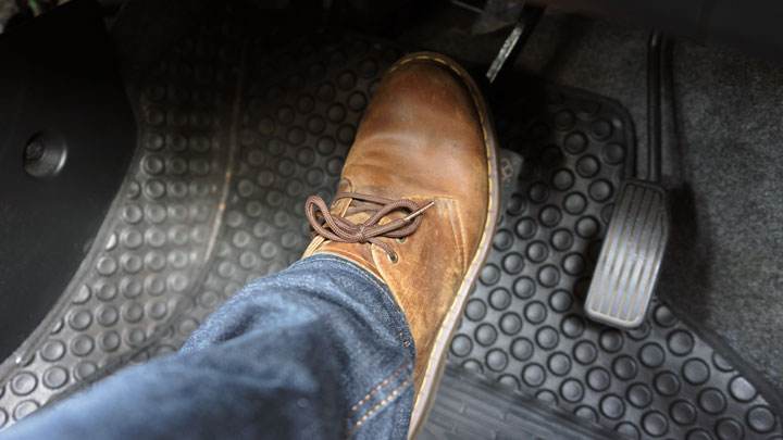
2. Brake Problems
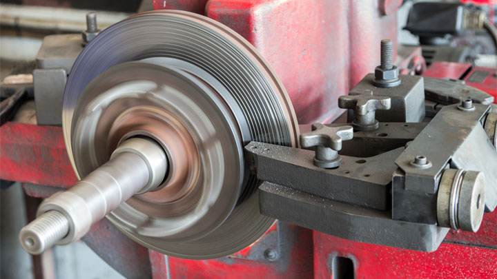
Have you recently inspected warped brake discs? If not, it might be the right time to check it, in case your car shakes upon starting. Even brake issues can cause the car to shake. The rotor is a shiny, silver, round-shaped component found in the disc brake system installed in vehicles. Significant wear can affect its original shape, making it look and function improperly.

So, if it’s not in shape, it will likely be mounted from the surface. The original shape of the rotors is flat, which, if damaged, can lead to intensified vibrations in your car. The brake discs are compressed with the calipers and brake pads, resulting in vibrations in your car. Therefore, a proper check of the brakes and rotors in time can help.
3. Unbalanced Car Wheels
Generally, a shaking car means there are issues with the tires. But most of us don’t realize that the problem could also come from the vehicle’s wheels. Sometimes, it’s not the tires but the wheels that make your car shake. In such cases, look for any traces of clay or mud stuck to the wheels, accessible simply by turning the car’s wheels.

If these metal squares contain something like dirt or mud, then consider it the right time to clean them to stop the car from vibrating. The mud stuck there unbalances the wheels, leading to a shaky car. So, clean the wheels on all sides to maintain balance. You can learn more about why the car shakes upon starting by checking some useful maintenance tips online.
4. Power Steering Problems
The power steering system helps you steer your vehicle more easily using hydraulic or electric assistance. If there’s a problem with the power steering system, it can cause shaking or vibrations when starting the engine. There are several potential reasons related to power steering that can make your car vibrate, such as:
- Low or contaminated power steering fluid
- Faulty power steering pump
- Worn power steering belt
Conclusion
We hope you have found the answer to your question, which was why does my car shake when I start it. So, why not apply these tips in advance to eliminate all these reasons behind a shaking car before it happens?
Unprecedented 1300-Car No Reserve Auction Event
The Ultimate Collector Car Liquidation
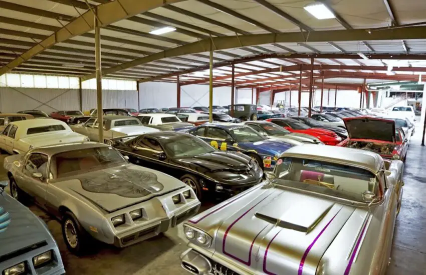
Automotive enthusiasts are witnessing an unprecedented event in collector car history as Greg Rusk’s massive vehicle accumulation heads to auction with no reserve prices. This extraordinary collection represents one of the largest single-owner vehicle liquidations ever to hit the market, featuring approximately 1,300 automobiles that will be sold to the highest bidders regardless of price.
A Collection Beyond Comprehension
What makes this auction particularly remarkable isn’t just the sheer volume of vehicles, but the mystery surrounding the exact contents. Even the collector himself cannot confirm the precise number of automobiles in his possession, creating an air of excitement and discovery for potential bidders. The diversity of makes and models spans multiple decades of automotive history, offering something for every type of collector.
No Reserve Pricing Strategy
The decision to sell all vehicles without reserve prices represents a bold move in the collector car market. This approach means every vehicle will find a new owner regardless of the final bid amount, creating unique opportunities for both seasoned collectors and newcomers to acquire pieces of automotive history. The absence of minimum prices typically generates heightened bidding activity and often results in surprising final values.
Historical Significance
Collections of this magnitude rarely appear on the open market, making this event particularly significant for automotive historians and preservationists. The vehicles represent a timeline of automotive design and engineering evolution, capturing moments in manufacturing history that might otherwise be lost to time. Each car tells a story not just of its design and purpose, but of the collector’s passion that brought them all together.
This auction promises to reshape the collector car landscape, establishing new benchmarks for what constitutes a major collection while providing unprecedented access to automotive treasures for enthusiasts worldwide.

The new brakes squeak causes
When you get new brakes installed in your vehicle, the last thing you expect is to hear them squeak or squeal again when you get home. But what does it mean when this happens? Is it normal or did the repair shop do a poor job?
The truth is, it depends on various factors. Because even though you might need to take it back to the repair shop or find a new one, sometimes it’s a completely normal condition.

Is It Normal for New Brakes to Squeak?
While it’s completely normal for some brake pads to squeak, the last thing you want to do is ignore it and assume everything is fine. This is because, even though it might be a normal condition, it could also be trying to tell you that something fairly serious is happening.
So, if you hear your brake pads squeaking, consider all the following potential causes, and if something doesn’t seem right, take a look at it or take it to a mechanic to have the brakes inspected.
Top Reasons Why Brakes Squeak or Squeal
Before looking at the specific causes of these noises, let’s discuss how these sounds are produced.
Vibration
Vibration of brake components can cause a squeak or squealing noise due to a phenomenon called “brake judder.” This occurs when the brake rotor or drum becomes warped or wears unevenly, causing the brake pads or shoes to vibrate and create a high-pitched noise.
Vibration can also cause brake components to rub against each other, leading to a squeak.
Friction and Heat
Friction and heat can also contribute to brake squeaking or squealing. When the brake pads press against the rotor or drum, they create friction that generates heat. This heat can cause the brake components to expand and contract, which can produce a high-pitched noise.
Furthermore, if the brake pads are made of a harder material or are not properly lubricated, they can create more friction and heat, which can lead to squeaking or squealing. This is because the increased friction can cause the brake pads to vibrate and create a high-pitched noise.
Additionally, if the brake components are dirty or contaminated with debris, this can also create friction and heat, which can lead to brake noises. For example, if brake dust builds up on the rotor or drum, it can cause uneven wear and create a squeak when the brakes are applied.
Causes of Squeaking Brakes After New Brake Pads and Rotors
There are a few potential causes for new brakes squeaking or squealing when you use them. Below, we’ve highlighted the five most common ones and how you can tell if that’s what’s happening with your brakes.
#1 – Cheap Brake Pads
When we talk about “cheap” brake pads, we don’t mean to give you a bad impression. Semi-metallic brake pads do a great job of stopping your vehicle, but low-end semi-metallic brake pads simply make noise when you brake.
If you opted for cheaper pads, there’s a good chance that’s why you’re not getting the quiet results you want when braking.
If you want to avoid this in the future, we recommend opting for high-quality ceramic brake pads. Not only do they last longer and improve braking performance, but they are generally quieter and don’t produce as much brake dust.
#2 – Poorly Mated Pads
When you replace brake pads, you’re supposed to either replace the rotors or resurface them. This allows the pads to mate with the rotors for a flush fit, giving them maximum braking power.
Not only that, but you need to break in the pads for them to work properly.
If you neglect either of these steps, you’ll lose braking power and you might hear squeaks or squeals when you brake.
#3 – Moisture on the Rotor
If you head to your car and hear a squeak in the morning when you brake, chances are it’s just the pads squeaking due to morning dew. This is a normal condition, and after braking a few times, it should go away.
The same can be said after washing your car. A bit of moisture on the rotor can cause temporary squeaking.
#4 – Dust or Debris Between the Pad and Rotor
Whenever something gets between the pad and the rotor, it makes noise. A little dust isn’t a big deal, even if it’s a bit noisy, but anything else (like a small pebble) can lead to serious problems.
Not only do debris between the pads and rotor make a loud noise, but they will also wear down the pads and rotor quickly and unevenly. Worse yet, it can significantly impact braking performance, thus leading to an accident.
#5 – Rusty Rotor

Even if you have new brake pads, it doesn’t necessarily mean you drive the vehicle a lot. If it sits for long periods, chances are you’ll just hear the brake pads wearing off the rust from the rotor when you drive.
After driving 5 to 10 miles on the road, you should have removed the rust from the rotors and the squeaking should go away.
Will the Noise Go Away on Its Own?
It depends on what’s going on. If the problem is from rusty rotors, moisture on the rotors, or even dust between the rotors and pads, the problem will go away on its own.
However, if the problem is from debris between the pad and rotor, chances are the problem will persist until someone removes the debris. Meanwhile, poorly mated pads or cheap brake pads mean the problem won’t go away until you change the pads and start over.
How Long Do Brakes Squeak After Being Replaced?
After replacing your brake pads, it’s quite common to hear squeaks or squealing noises. This is because new brake pads need a break-in period to fully seat against the rotors.
During this time, you might be wondering how long this noise is going to last, right? Let’s discuss it.
Typically, brake squeaking should go away after a few days, during which you drive about 100 miles for your brakes to properly bed in. However, the duration can change depending on the quality of your brake pads and rotors, as well as your driving style.
To reduce the risk of brake squeaks during the break-in period, you can follow these tips:
- Drive gently and avoid sudden stops
- Perform a proper break-in procedure after installing new brake pads
- Inspect the rotors for any signs of grooving or glazing
- Regularly check and maintain your brake system
Remember, if your brakes are still squeaking after a few days and it bothers you, it’s a good idea to have them checked by a professional. Keep in mind that brake noises after a replacement are usually not a cause for alarm, but your safety is always the priority.
When to Take Your Car Back to the Repair Shop
If you feel something or hear noises other than a squeak or squeal when braking, you should take the vehicle to a mechanic as soon as possible. Additionally, if the sound is abnormally loud, you should also take it back to the repair shop.
While it might be a bit tricky to determine if the sound is abnormally loud if you don’t know what the acceptable range is, try to use this as a rule of thumb.
With the windows up and the radio on at a low level, you shouldn’t be able to hear the squeaks or squeals. If you can, either something is going on or there’s poor workmanship. In either case, the repair shop should fix it for you.
Can I Spray Something on My Brakes to Stop Them from Squeaking?
If you’re experiencing squeaky brakes, using a brake cleaner spray can help address the issue. These sprays can remove dirt and contaminants from your brake components and leave no residue.
They typically dry or evaporate quickly and can be safely used on your brakes. It’s important to note, despite what you might have heard, that spraying WD40 on brakes is not a good idea.
Here are some simple steps to apply a brake cleaner spray to your brakes:
- Make sure your car is parked on a level surface and the engine is off.
- Loosen the lug nuts on your wheels, then lift your car with a jack and secure it on jack stands.
- Remove the wheels to expose the brake components.
- Use a designated brake cleaner spray and follow the manufacturer’s instructions. Typically, hold the can about 10 to 12 inches from the brake components and spray, ensuring to cover the entire surface of the brake pads, rotors, and calipers.
- Let the components dry completely before reinstalling your wheels.
- Reinstall the wheels, lower your car, and tighten the lug nuts.
Keep in mind that while a brake cleaner spray can help reduce or eliminate brake squeaking, it might not be a permanent solution. If the squeaking persists, it could be a sign of another issue, such as those listed earlier in this article.
Is It Safe to Drive If the Brakes Squeak or Squeal?
When you hear your brakes squeak or squeal, it’s natural to wonder if it’s safe to continue driving. In most cases, these noises are more of a nuisance than a sign of danger. However, it’s essential to understand when these noises might indicate a potential problem with your braking system.
Brakes can squeak for various reasons, such as:
- Morning moisture
- Surface rust on brake rotors
- New brake pad composition
- Normal wear
In these situations, the squeaks are usually not a concern. The noise should go away as the moisture evaporates or once the new brake pads have settled in. If the noise persists, it might be a good idea to have your brakes checked just to make sure everything is working properly.
But persistent or unusual brake noises could indicate that your brake hardware needs lubrication or that components are worn out. If the sound becomes a constant grinding or if your vehicle’s performance is affected (such as a wobble or pulling to one side when braking), it’s important to have your brakes inspected and serviced immediately to prevent further damage or accidents.
Other Brake Noises

While squeaks and squeals are two types of brake noises you might hear, they’re not the only ones. Below, we’ve highlighted three other brake noises you might hear and given you a brief overview of what each means and what you should do if you hear them.
#1 – Grinding
If you hear a grinding noise when you brake, it indicates a major problem. This is because when you hear grinding, it’s usually metal-on-metal contact. The calipers might be hitting the brakes or something else might be going on.
If you have new brakes and hear a grinding noise, take it straight back to the mechanic and have them fix it for you. You should also have the work inspected, as metal-on-metal grinding can quickly lead to additional damage, and they should fix that for you as well.
#2 – Thumping
Thumping noises typically occur when your rotors are warped. If you didn’t choose to replace the rotors, but the repair shop resurfaced them for you, it means they botched the job.