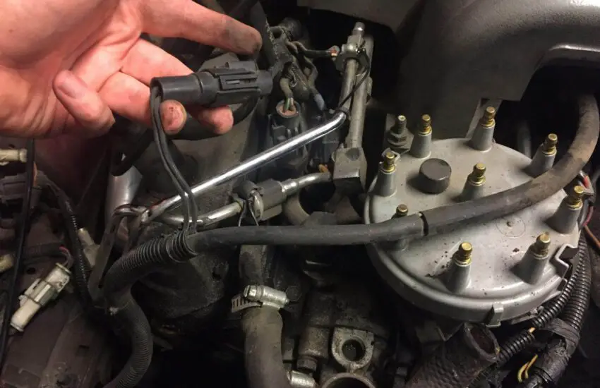
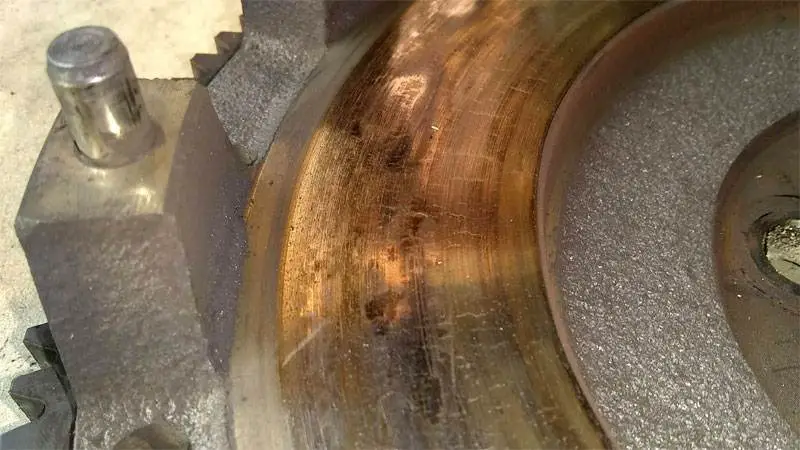
Symptoms to monitor while driving with a faulty purge valve
There is a system called the “evaporative emission control system,” which, in turn, contains a vapor canister purge valve. The valve is responsible for regulating the amount of fuel vapor exiting the charcoal canister. The purge valve is known to work in sync with the charcoal canister to recycle emissions as they need to be eliminated through the internal combustion process. That is why driving with a faulty purge valve can affect the engine.
Are you concerned about how to tell if the valve has malfunctioned? Here are the five most common symptoms to watch for that indicate the purge valve needs repair or replacement.
Symptoms of Driving with a Faulty Purge Valve
If you have a faulty purge valve, the situation would be worse than a non-functioning charcoal canister. Here are the symptoms that could help you decide that it’s the purge valve causing problems.
1. The Check Engine Light Turns On
Although there are dozens of reasons that can lead to the check engine light turning on, a faulty purge valve could be one of them. There are sensors in the car’s system that monitor the operation of the purge valve, and once the signals from the valve fail to transmit, an indication is the result. When the sensors detect a loss of signal from the valve, the information is then communicated to the engine control unit. That is why the dashboard light turns on, indicating that you have driven with a faulty purge valve.
Pay attention to the check engine light, then check your valve.
2. Rough Idling
Do you often get stuck in traffic with the engine light on? If so, you’ll know how smoothly or roughly your vehicle handles it. If you notice a change that leads to rough idling, you should consult a mechanic. It’s likely that the purge valve is faulty and requires your attention. Do not ignore the problem, as it could lead to the engine stalling completely because vacuum leaks are very likely to occur.
3. Difficulty Starting
When your car is experiencing a vacuum leak, you may struggle to start the car. This problem is even more consistent when it’s the purge valve that has malfunctioned. The vacuum leak would create an entry point for air to enter the engine and significantly disrupt the combustion process. This is not a favorable situation! You can also refer to maintenance tips for other issues that may cause delays in starting your vehicle.
4. Poor Engine Performance
If you’re a fan of high speeds, a faulty purge valve will ruin all the fun of driving. Engine performance would become poor, and no matter how hard you try, power output would deteriorate. If you already miss your smooth rides, you should consult a mechanic. You need to address these small issues when driving at your desired speed.
5. Failed Emission Tests
Did you know that a purge valve prevents toxic hydrocarbons from being released from the exhaust pipe? So when you have a faulty purge valve, toxic hydrocarbons escape from the internal system. Such a situation would not be good for your emission control tests. With more toxicity in the air, you would also increase your carbon footprint. If it’s the purge valve that has caused the mess, you’d better repair or replace it as needed.
Test your emissions for a faulty purge valve
Summary
These are the five most common symptoms you need to watch for when driving with a faulty purge valve. Never forget that the healthier your car is, the better the driving experience.
What is the purpose of air suspension and how does it work
Upgrading your air suspension can improve your car’s comfort.
Whether it’s speed bumps in a residential cul-de-sac, low curbs in driveways, or even potholes or unintended bumps on the road, it’s unfortunate that UK roads aren’t particularly kind to vehicles carrying heavy loads or high-performance sports vehicles. There have surely been times when you wished you could raise your truck or car’s suspension to help it clear an obstacle more easily. Similarly, sometimes when there’s nothing in the back of your van, you sit quite high and feel like you’re riding much slower than usual. While normal suspension systems based on coils and springs are comfortable and provide good vehicle handling, they don’t offer you the ability to lift or lower your vehicle. Enter air suspension.
Air suspension, or air-ride, has been around for a long time, with aftermarket kits first appearing for installation on cars as early as 1920. Besides providing comfort for drivers, it was initially used as a self-leveling suspension for heavy loads. People even used it to help illegally transport moonshine! That’s why, even today, many new trucks and trailers come equipped with air suspension systems, and there’s a whole range of aftermarket kits that can be fitted later.
Air Lift is one of the most well-known companies in aftermarket air suspension and has been around since 1949. Although we tend to associate air-ride as being more comfort-oriented than performance-focused, it was extremely popular in drag racing and NASCAR in the 1950s and 60s.
So, what is this air suspension, why do people want it, and what are the pros and cons of using air suspension?
WHAT IS AIR SUSPENSION AND HOW DOES AIR SUSPENSION WORK?
Conventional shock and spring suspension systems with steel components provide the vehicle with excellent handling and fantastic overall performance. Air suspension, however, replaces these components with robust rubber airbags that can be inflated using an onboard or external air compressor. This allows the vehicle to lift or lower depending on how much the airbag is inflated and can make a car much more comfortable to drive or give it a better appearance. Does air suspension affect performance? Yes – but not necessarily in a bad way. Modern kits also include features like adjustable camber top mounts and adjustable damping, meaning you can have the best of both worlds.
It’s important to note that there are two different types of air suspension: “semi” air suspension and “full” air suspension.
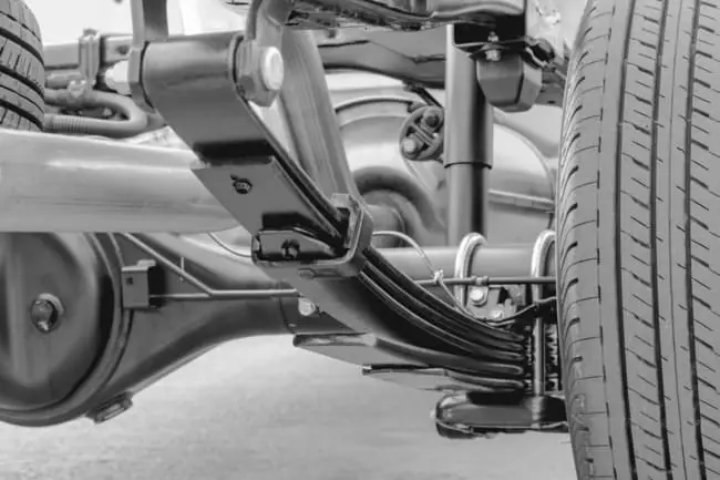
“Semi-air suspension” supports a car’s existing suspension. It’s often found on heavy goods vehicles or trucks. An air spring is installed between the chassis and the rear axle, which increases the vehicle’s ride height and generates greater spring travel. In this way, semi-air suspension helps increase the level of comfort and stability when traveling in your vehicle.
If you’re experiencing suspension issues, full air suspension could be a fully automatic and adjustable solution. The conventional suspension system is completely replaced by a full air suspension system that filters out road surface irregularities, making the ride much more comfortable.
Ultimately, the only major difference between conventional and air suspension systems is that instead of the car resting on a coil spring, it rests on a rubber bellows filled with compressed air. Since the bags aren’t pre-inflated, they are supplied by an air tank and an electric air compressor, and the car can be raised and lowered simply by inflating and deflating the bag.
WHAT ARE THE KEY COMPONENTS OF AN AIR SUSPENSION SYSTEM?
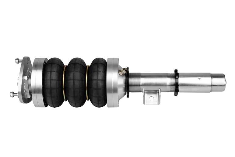
AIR SPRINGS (BAGS)
These are robust rubber bases that replace the coil spring in a conventional setup. They come in two main styles: the coilover setup or the conventional style. In the coilover setup, the bag has a hole in the middle allowing the shock absorber to pass through it. In the conventional style, the bag is completely independent of the shock absorber.
Modern airbags don’t look like a balloon filled with air as we might imagine. They are solid and durable and designed to expand and contract only vertically. When fully inflated, they can have an air pressure of 100 psi.
SHOCK ABSORBER
If you have a suspension design where the spring is mounted separately from the shock absorber, the same shock absorber you would have used with your conventional coil spring can be used. Fortunately, nowadays, with the growing popularity of airbags in the tuning scene, there are now coilover-type kits for a wide range of cars, offering a matched shock absorber and airbag combination. These kits not only simplify installation but also improve handling and ride quality. Many of them feature shock absorbers with adjustable height platforms for the bags, adjustable damping, and even adjustable camber top mounts.
COMPRESSOR
Air doesn’t magically enter the airbags. That’s what the compressor does. All air suspension kits require at least one compressor, and you’ll typically find that the one supplied is quite small and compact; they often fit perfectly in the car’s boot. They often run on a 12-volt power supply, so they won’t drain your battery. The big issue, however, is that they are often very noisy.
AIR TANK
This compressor noise is what makes the air tank necessary. You could do air-ride without it, but the pump would have to run far too often, and it would take too long to lift the car unless the pump was gigantic. An air tank is used as the main supply for the airbags, and the air compressor is used simply to keep the tank above the minimum pressure. Depending on their size, air tanks allow the suspension to be raised at an acceptable speed without the compressor needing to kick in. However, this also has to be stored in the boot of many cars. You just need to decide what’s more important to you; more boot space or a larger tank.
ADVANTAGES
IMPROVED FUEL ECONOMY
The higher your suspension is, the greater the wind resistance of the truck and trailer, meaning your fuel economy will be worse.
Advanced air suspension systems can adjust the ride height based on the load weight and the type of journey you’re making. For long, smooth highway trips with light loads that compress the suspension less than heavy loads, the suspension can be set lower to maximize your fuel economy. For heavy loads, the suspension can be made as firm as needed, and the vehicle remains lower to the ground due to the heavy load. In both situations, the vehicle stays low, and you save fuel. In a conventional suspension system, if the load was light, the vehicle’s suspension, designed for heavy loads, would remain stiff, and your fuel economy would be much worse due to resistance.
MORE ENVIRONMENTALLY FRIENDLY DUE TO REDUCED CO2 EMISSIONS
Thanks to this decreased fuel consumption and smoother driving, it automatically means less fuel used, journeys are quicker and shorter, and consequently, it’s much better for the environment. That’s something we can all be happy about!
REDUCED VIBRATIONS
Better for your cargo and better for your back on long journeys, air-ride reduces vibrations in the truck or car. Back pain isn’t just something that comes with age; Long-haul truck drivers can experience it if they remain seated for long periods. Vibrations also cause fatigue and discomfort, meaning a happier, fresher, and ultimately safer driver.
Similarly, goods transported by the truck are less likely to be damaged or shift in the back of the van or truck (even though packaging and load restraint methods these days are very good anyway).
Alongside this, a trailer can be used for more types of loads when the suspension setup is flexible. Fragile loads like glass are less likely to be damaged, and loads with difficult weight distribution can be leveled.
IMPROVED TIRE WEAR AND HANDLING
Fewer vibrations and better load distribution through leveling lead to better tire wear. Some air suspensions can even lift unused axles, thereby extending the life of those tires.
Suspension is also a significant factor in how a vehicle behaves. Better suspension could mean a lower risk of rollover. If the vehicle is higher off the ground, it’s much harder to handle, and this can be a problem for vans or trucks with a rigid suspension system when they’re not carrying a load.
EASY INSTALLATION
The advantage of these systems is that they are very easy to install. Five years ago, it might have been a bit different, but nowadays, there are various direct replacement kits for a large number of popular cars. While installing a full air suspension system on a car is still a job for professionals, for most of us, installing a semi-air suspension is no more difficult than installing a set of coilovers and shouldn’t take more than a day. These “plug-and-play” semi-air suspension kits are also relatively inexpensive. Where to install the air suspension isn’t much of a problem either, as these kits are designed to fit current suspension systems, provided there’s boot space for the tank and compressor.
DISADVANTAGES
This isn’t to say everything is perfect for air suspension systems, and they do have some drawbacks.
Some truck drivers still claim that the traditional leaf springs of a semi-trailer can provide a better ride, regardless of the load. This could be partly because air suspension can weigh about 50 kg more than leaf spring suspension. This extra weight could actually counteract the “better” handling provided by lowering the vehicle and make driving more difficult.
Since it weighs considerably more, it might be possible to install other aerodynamic devices such as trailer skirts and cab side fairings to achieve the same fuel economy gains.
Leaf spring suspension is also much more durable and typically doesn’t require much maintenance for the first 5 to 7 years, after which it will need to be tightened. In contrast, with air suspension, cars need to be serviced more frequently – up to 3 times the cost over the first ten years. Air suspension can leak, and you’ll need to keep spare air lines and other parts. Air suspension also needs to be tested more frequently, which takes time.
Although leaks are rare, finding them can be a bit frustrating. You’ll also lose some of your boot space. You need a decent-sized tank to prevent the noisy compressor from kicking in when you lift the car. Height changes aren’t as fast as with hydraulics.
Common air suspension problems can also include the air suspension being inactive due to a leak or the control unit being broken. The compressor could also fail, or the air tank could lose pressure. All these components then need to be serviced or replaced, which could cost you more in parts and repair fees at a garage.
THE VERDICT
So, what’s it really like to have air suspension and use it daily? Better than most people might expect. A good kit, properly set up, will perform much better than the conventional suspension of vans or trucks. For your average passenger car, it might not be worth it, as regular suspension will do the job just fine. That said, people have willingly drifted and set respectable lap times on air setups, so if you have a particularly low-slung car, like a Porsche Carrera or almost any Mercedes S or E-Class, it could be an option for you.
You will, of course, lose a bit of boot space to the compressor and air tank, but no more than with a subwoofer box or a nitrous bottle, and there’s very little weight penalty in adding the air-ride kit.
Don’t be mistaken, however: air-ride doesn’t offer the instant height jumps that hydraulic systems do (you won’t be bouncing like a lowrider), but it actually only takes a few seconds, and with a correctly sized tank, it can be done quietly too. If you’re wondering if air suspension is reliable, rest assured it is, and countless people have these systems on their daily-driven cars with no issues at all.
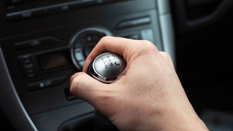
Driving the clutch: what is it and how to avoid it
You’ve probably heard the phrase “riding the clutch.” It’s a term often used by driving school instructors, and you’ve likely sensed it’s a bad driving habit, but what exactly is the clutch and why should you care about it?
“Riding the clutch” refers to unnecessarily keeping the clutch pedal partially depressed. To help you understand why this is bad for your car, we’ll explain the role of the clutch, proper clutch control techniques to show the consequences of riding the clutch, as well as ways to break this bad habit. Avoiding riding the clutch is not only a fundamental aspect of driving but also of properly maintaining your beloved vehicle. Why? Keep reading to find out.
Riding the Clutch: Why Should I Care?
Simply put, in any vehicle equipped with a manual transmission, the clutch is the mechanical device that transfers rotational power from the engine to the transmission, meaning to the wheels. To do this, it connects the shaft coming from the engine and the shafts that turn the wheels.
The clutch is a crucial component because the engine generates power all the time and has parts that are constantly spinning, but the wheels do not spin constantly, and when they do, they may not spin at the same speed as the engine parts. That’s where the clutch comes in. The clutch allows the car to accelerate, slow down, or come to a complete stop without stalling the engine.
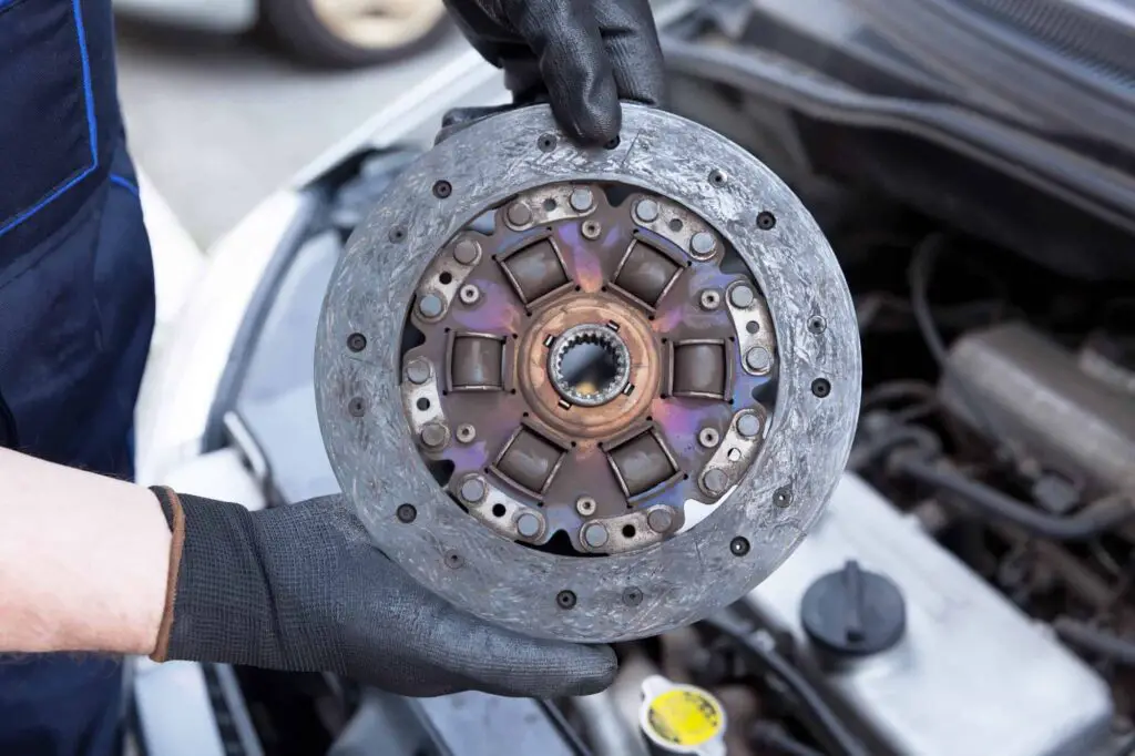
The clutch disc or plate is part of a vehicle’s manual transmission system that transmits power from the engine to the wheels. Photo Credit: The Motor Guy
To facilitate gear changes, the clutch temporarily interrupts the connection between the wheels and the engine long enough for you to shift gears to accelerate or decelerate. It can also be said that the overall purpose of a clutch is to maximize the efficiency of the system by controlling the connection between rotating parts moving at different speeds.
The clutch/transmission system has many parts. If you master clutch control, a well-treated clutch can last up to 80,000 miles. But if you have the bad habit of “riding the clutch” as well as others like riding the clutch in certain situations, you will need to replace these parts much sooner, sometimes as soon as you reach 35,000 miles. And that won’t be cheap.
The Principle of Clutch Control
In a vehicle with a manual transmission, the basic principle of smooth clutch control is to fully disengage the clutch when shifting gears by pressing the clutch pedal to the floor with your left foot, and then to re-engage the clutch by lifting the pedal to release it completely. Full disengagement before re-engaging will prevent the gears from clashing and thus allow you to shift smoothly.
When the clutch pedal is fully depressed and the clutch is fully disengaged, there is no longer a direct connection between the engine and the transmission shaft, so no torque is transmitted from the engine to the wheels. In the re-engagement phase, when you completely remove your foot from the pedal, the connection is complete again between the engine and the transmission shaft. The engine can now directly transfer torque to the transmission shaft.
During a proper gear shift, the clutch pedal should be released quickly to re-engage the engine to the transmission shaft. When the engine and transmission shaft re-engage and their speeds equalize, you will feel a distinct jerk, characteristic of a manual transmission vehicle.
However, in some situations, the clutch is intentionally released slowly. In this case, the clutch disc will “slip” against the flywheel, and this amount of friction will allow the engine a smoother transition to its new rotational speed.
Here, the clutch disc will be partially engaged and the transmission shaft will therefore only receive a fraction of the engine’s rotational power. This is commonly referred to as “slipping the clutch” or “feathering the clutch.”
Such regular slipping of the clutch disc against the flywheel causes clutch wear that is similar to the wear of a brake pad during braking. Admittedly, some wear is natural and unavoidable, but you can still minimize it with better clutch and shifting techniques.
The general rule is to release the clutch as close as possible to the correct engine speed for the gear and vehicle speed. That is, when upshifting, you will need to let the engine speed drop before releasing the clutch for a smoother transition. Conversely, when downshifting, you will need to increase the engine speed with the accelerator before releasing the clutch. A smoother transition directly results in minimal clutch wear and reduced maintenance costs.
What Does Riding the Clutch Mean?
Riding the clutch occurs when a driver fails to remove their foot from the clutch pedal after changing gears. Photo Credit: nearsay.com
In a vehicle with a manual transmission, riding the clutch refers to the practice of unnecessarily keeping the clutch partially disengaged. This usually happens when a driver fails to remove their foot from the clutch pedal after changing gears.
This results in the clutch disc slipping against the flywheel and some of the engine’s power not being transferred to the transmission and wheels. The friction between the clutch disc and the flywheel creates heat and eventually causes premature wear on your clutch.
Habitually resting your foot on the clutch while driving instead of on the floor or on the dead pedal is a bad habit to get into. It’s a very common habit among beginner drivers, but it’s not limited to learners only. Riding the clutch is something anyone can do while driving.
You should keep your foot away from the clutch at all times, unless you need to start your car, shift up or down gears, and come to a stop. Even if you think no pressure is applied when the foot is simply resting on the clutch pedal, it certainly is.
Although this light pressure is not enough to allow the clutch disc itself to slip, it is enough to keep the release bearing against the release springs. This causes the bearing to keep spinning, leading to premature bearing failure.
Thus, treating your clutch pedal as a footrest can lead to extra strain and wear on certain components. And since the clutch is considered a wear item just like tires and brakes, clutch wear will not be covered by your new car’s warranty. You will eventually need to repair or replace your clutch much sooner, and that’s not cheap.
The cost of repairing a clutch can range from $500 to $2,500, depending on the make and model of your car. Clutch replacement is more affordable if you own a Japanese economy car, and will be much more expensive for performance cars, exotic cars, and European models.
It is worth noting that while riding the clutch is a bad habit to get rid of, many drivers regularly and effectively use this technique in traffic jams, as it is easier to control the throttle and acceleration at very slow speeds. The clutch is also intentionally used when driving in reverse, as the distance to travel is short while full engagement of reverse gear results in too high a speed.
Another note is that riding the clutch should not be confused with “coasting” or “freewheeling,” a common practice where the clutch is pressed all the way down, allowing the car to roll either downhill or by inertia, or to roll into a parking space or over speed bumps by inertia. While this technique is not damaging to the car, it can be considered a tricky way of driving since you won’t be able to accelerate quickly if needed.
How to Avoid Riding the Clutch
Automatic transmissions are undoubtedly convenient, especially in city traffic. But a manual transmission continues to win hearts for the pure, unadulterated driving pleasure it offers. However, it is not as convenient as an automatic transmission, so you will need to learn to find a balance in your driving. If you want to enjoy your manual transmission, you must develop good habits to properly care for your clutch.
It takes some effort to break the ingrained habit of riding the clutch. It might take you a bit of practice to feel like you’ve really gotten the hang of it, but it’s worth it, both to avoid premature and costly replacement and to acquire good driving habits.
Now that you understand the meaning of riding the clutch, you need to learn how to avoid doing it.
If you have a habit of riding the clutch, the biggest clue that you are causing excessive wear to the clutch is a distinctive burning smell from the clutch discs as they slip on the gearbox shaft. If you notice this smell, adjust your position accordingly.
Automatic or Semi-Automatic Gearbox
There are several ways to avoid riding the clutch in a manual car, but the other way to avoid it completely is to buy a car with an automatic or semi-automatic gearbox. With no pedal to rest your foot on, and thus more footwell space, you will never have to worry about riding the clutch and paying for expensive repairs if the clutch fails prematurely.
Adjust Your Driving Position
One reason for riding the clutch could be a poor driving position. If you sit too close to the pedals, you may not have enough legroom to place your left foot in a comfortable position elsewhere and you might end up unintentionally resting it on the clutch pedal.
To fix this, you need to find ways to adjust your driving position. The best way to do this is to press the clutch pedal with your leg locked in a completely straight position, then move the seat until you are pushing the clutch pedal against the bulkhead in the driver’s footwell. Once the seat is adjusted, remove your foot from the pedal and you should have enough legroom to comfortably move your foot away from the clutch pedal and rest it on the floor.
Many cars are equipped with a dead pedal (footrest) which makes it much easier to avoid riding the clutch. However, if you are driving a car with a cramped footwell, see if you can place your foot behind the clutch pedal. This is not ideal, but at least one can drive without touching the clutch pedal too much.
Use Neutral More Often
The general rule for manual transmission vehicles is to use neutral more and the clutch less. You need to have your foot on the clutch to start your car, to shift up or down gears, and to come to a stop. Otherwise, keep your foot off the clutch.
When going down a slope, downshift and use your brakes or shift into neutral and use your brakes to slow down. In traffic, plan for a greater distance between your car and the one in front of you and ride a bit more with the flow of traffic.
When stopping at a red light, do not leave your car in gear as this would cause unnecessary wear on your clutch. When you leave your car in gear while stopped, you are essentially pressing the three main parts of your clutch against each other: the spring, the bearing, and the diaphragm.
Instead, release the clutch, put your car in neutral, and use your brake until the light changes. This allows it to relax and avoid excessive wear.
Shifting Gears: Be Quick and Decisive
When you need to change gears, try to look far down the road so you have the opportunity to anticipate obstacles you will encounter. The goal is to try to maintain a constant speed rather than shifting gears from time to time.
Also be decisive and quick. Don’t linger when shifting gears. This is a common problem for new drivers when they are first learning to drive a manual vehicle. Shifting gears only takes a few seconds. The longer you press the clutch pedal with each gear change, the more unnecessary pressure and wear you put on your clutch.
Even if the gear shift happens in the blink of an eye, you will shift gears multiple times during an average journey, which can add up very quickly over time.
Use the Handbrake When Parking
Whenever possible, you should use the handbrake to secure the car when you park instead of leaving your car parked in gear. Leaving a vehicle parked in gear puts pressure on the clutch even when the engine is off. Instead, using the handbrake will reduce the pressure on the clutch disc when you are not driving, so less wear in the long term.
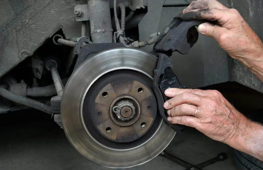
Brake Pad Thickness: What is the Minimum Depth
The correct thickness of brake pads is essential not only for the proper functioning of the engine but also for road safety. Replacing the pads at the right time will save you a lot of money in the future. But at what thickness should brake pads be replaced? How to properly perform brake pad measurements and take the necessary actions? Let’s get to the bottom of it.
What are brake pads?
Brake pads, located between the brake shoe and the brake drum, are essential to a vehicle’s braking system. If they are damaged or do not have the required thickness, other components of the braking system – rotors, calipers, and discs – will wear out. It is important to determine the right time to replace the pads to avoid dangerous driving conditions.
New and old brake pads. Source: Drone Festival
Brake pad thickness: minimum and recommended limits
Brake pads consist of steel plates, shims, and friction materials. There are two layers of rubber coating and thermal insulation coating on the outside. Like all other things, these materials wear out over time. Additionally, hard driving and poor road conditions contribute to accelerating deterioration.
The normal lifespan of brake pads is between 30,000 and 35,000 miles. However, this can be more or less depending on the car’s make and model, driving habits, and road conditions.
New brake pad thickness
So, what is the thickness of brake pads when they are purchased new? Well, the new brake pad depth is about 12 mm. That’s the standard thickness, and it will last roughly 35,000 miles.
If you are an aggressive driver who often uses the brakes, they won’t last long. Moreover, their lifespan is shorter than usual when you have to brake frequently due to heavy traffic.
Minimum brake pad thickness
Mechanics suggest replacing brake pads because continuous engagements make their friction material thinner. When the material wears away completely, the next step is brake failure.
The brake pad thickness should be at least 6.4 mm or more for proper functioning. You can sometimes get away with thinner pads. But prompt replacement when the thickness is between 6.4 and 3.2 mm will prevent serious damage to the braking system.
Symptoms of thin brake pads
A physical inspection is enough to check if the pads meet the recommended thickness. You will only need a flashlight, an inspection mirror, and a measuring device to do it.
You can measure the thickness with simple instruments. Source: eBay
Some warning signs not to ignore are:
Metallic grinding or rumbling noise, which occurs when the brake discs and calipers rub against each other. This means the pads are completely worn out.
Squealing, grinding, or groaning when you brake. If the noise doesn’t go away after several times, you need to check the brake pads.
Some cars have a dashboard light to give a thin warning.
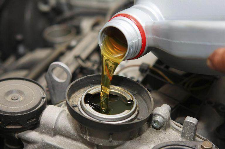
What happens if you use regular oil instead of synthetic oil
Oil is the lifeblood of an automobile. It not only provides power to your car but also ensures the proper functioning of other components. Oil absorbs excess heat and contains additives that remove harmful chemicals. After driving thousands of miles with your vehicle, the oil needs to be changed. Nevertheless, some still wonder what happens if you use conventional oil instead of synthetic oil in their car.
Here, you will understand the effects of conventional or synthetic oil on your car’s performance. You can also search online for the best car maintenance tips to better understand the effects.
What Happens If You Use Conventional Oil Instead of Synthetic?
We will now demystify the reasons for what would happen if you switched to conventional oil instead of synthetic oil for your car. Some vehicle owners might think it’s bad to switch from synthetic oil to conventional oil. We will help clear up the confusion.
1. Crude Manufacturing
Unlike synthetic oil, conventional oil is distilled and refined from crude oil. Crude oil is a naturally occurring liquid fossil fuel. On the other hand, companies artificially prepare synthetic oil from chemical compounds to mimic the properties of natural oil. They manufacture it according to the requirements of modern vehicles. You can search online if you want to know what happens if you use conventional oil instead of synthetic oil in your car.
Know what happens if you use conventional oil instead of synthetic. (Photo: Siarhei Hivoin / iStockphoto)
2. No Engine Cleanliness and Protection
As conventional oil circulates through the vehicle’s engine, it slowly degrades, leaving behind harmful deposits and even leading to sludge formation. This can affect your car’s engine performance and the vehicle’s lifespan.
Synthetic oil contains minimal impurities and is more resistant to sludge. It keeps the car’s engine cleaner and ensures smooth and long operation.
3. Conventional Oil = Bad Choice for Driving in Extreme Temperatures
Your car’s engine generates heat when you take a long trip with your friends. This causes the oil to degrade. Synthetic oil performs better under extreme conditions because it is made with precise engineering. It can easily withstand heat, allowing your car’s engine to last longer.
Conventional oil would take longer to reach its ideal viscosity in cold weather. It might not provide the required lubrication when you try to start your vehicle.
4. Cost Increases
Your auto mechanic might charge you around $30 to $45 for a conventional oil change. Fully synthetic oil costs between $70 and $100 depending on the vehicle. Full synthetic may cost you a bit more, but it increases the engine’s lifespan by two to three times.
A regular oil change would cost you between $120 and $180. That’s a bit more expensive than synthetic oil. You can also check online for the best car engine oil change tips.
5. Less Oil Longevity
Do you want to know what happens if you use conventional oil instead of synthetic oil? Synthetic oil should be changed after a minimum drive of 10,000 to 15,000 miles. Conventional oil needs to be changed every 3,000 to 5,000 miles.
What Should I Do After Using Conventional Oil Instead of Synthetic?
If you accidentally used conventional oil instead of synthetic oil in your car, you can take a few steps to minimize any potential damage:
Check the oil level: Make sure the oil level is correct and there is enough oil in the engine. If the oil level is low, add more oil if necessary.
Monitor the engine: Keep an eye on the engine and listen for any unusual noises or performance issues. If you notice problems, such as knocking or reduced power, it’s best to have the vehicle inspected by a qualified mechanic.
Change the oil: If possible, it’s best to drain the conventional oil and replace it with the correct type of synthetic oil as soon as possible. This will help ensure the engine is properly lubricated and protected.
Follow the manufacturer’s recommendations: Make sure to follow the manufacturer’s recommendations regarding oil type and change intervals in the future to avoid any potential damage.
Although using conventional oil instead of synthetic oil may not cause immediate engine damage, it’s important to address the issue as soon as possible to avoid any potential long-term damage. If you’re unsure how to proceed, it’s best to have the vehicle inspected by a qualified mechanic.
Why Can’t You Go Back to Conventional Oil After Synthetic?
Although it is possible to switch back to conventional oil after using synthetic oil in your car, it is generally not recommended. Here are a few reasons why:
Synthetic oil lasts longer: Synthetic oil is designed to last longer than conventional oil, meaning it can go longer between oil changes. If you switch back to conventional oil, you’ll need to change it more frequently.
Provides better protection: Synthetic oil is designed to provide better protection for your engine, especially in extreme temperatures or under high-stress conditions. If you switch back to conventional oil, you may not get the same level of protection for your engine.
Compatibility issues: Some engines are specifically designed to use synthetic oil, and switching to conventional oil could lead to compatibility issues or even damage the engine.
Can You Put Synthetic Oil in Any Car?
Although synthetic oil seems very good, it’s important to consult your owner’s manual or a qualified mechanic to determine if synthetic oil is recommended for your specific vehicle make and model. But in general, synthetic oil can be used in many vehicles designed to use conventional or mineral oil.
Does It Hurt to Mix Synthetic Oil with Conventional Oil?
It is not recommended to mix conventional oil with synthetic oil. Although, in the short term, it may not damage the car’s engine, if you mix these types of oil for your car over a long period, it could cause engine problems, affecting the vehicle’s performance.
Summary
We hope you have an answer to what happens if you use conventional oil instead of synthetic oil in your vehicle. So, go ahead and read this when you want to find the answer to your query.
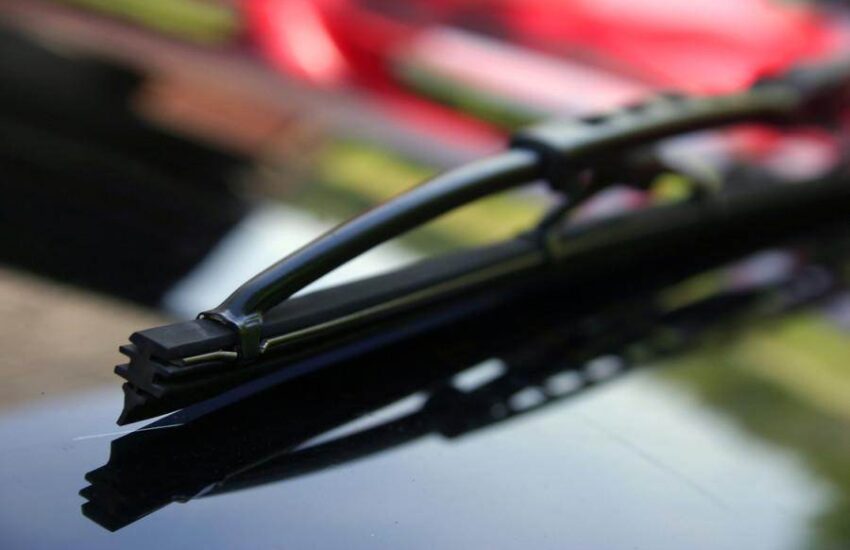
How to prevent windshield wipers from squeaking
It’s painful when you go on a long car journey because the noise prevents you from relaxing, listening to music, or focusing on the road. How to stop windshield wipers from squeaking? Why do they make this noise in the first place? Follow along!
Why do windshield wipers squeak?
Is there anything more annoying than squeaky windshield wipers while you’re driving? This awful, repetitive noise is distracting and almost impossible to ignore.
There can be several possible reasons that cause windshield wipers to squeak. It could be simple dirty wipers or more complicated issues like a cracked or worn wiper assembly.
The good news is that faulty wipers are not an expensive or tricky fix, but finding the source of the problem requires patience and some trial and error.
How to stop windshield wipers from squeaking?
You should not ignore squeaking wiper blades, as conditions could deteriorate if you don’t fix them at the right time.
Keeping them running will put extra pressure on them, leading to their failure or damaging the expensive windshield.
So, how to stop windshield wipers from squeaking before they lead to something worse? Follow these tips:
1. Regular Cleaning
One of the potential causes of windshield wiper squeaking is the buildup of dirt and grime on the windshield.
A thorough cleaning of the blades and the glass will solve this issue, and you should do it at least once a week to prevent it from recurring.
Regular cleaning is important. (Photo: anpadeh)
Use an ammonia-free glass cleaner to clean the windshield glass. Spray it on the surface and wipe it off with a microfiber towel or a squeegee.
You can apply the same solution to the blades or spray rubbing alcohol or warm soapy water. Lift the wiper blades off the surface and rub the solution into every crevice.
2. Wipe Off Windshield Wax
Some people apply a water-repellent product to the glass. It causes raindrops to slide off the windshield and improves visibility in wet weather. If the squeaking started right after applying such a product, you need to remove it.
3. Top Up Windshield Washer Fluid
Lack of moisture on the windshield glass can also cause bad wipers. Refill the windshield washer fluid if it’s low or empty. The blades need proper lubrication to glide over the windshield without making noise.
4. Fixing the Wiper Blades
How to stop windshield wipers from squeaking? Simple! Replace the wiper blades if they are cracked or worn.
Deformed blades cannot slide smoothly over the glass surface. The result is an annoying rattling noise. However, blades are inexpensive and easy to replace.
Fix the wiper blades if they are cracked. (Photo credit: Shutterstock)
Sometimes, squeaking can be the result of how the wiper assembly is attached. Screws that are too tight or too loose can cause this screeching sound.
This happens due to temperature changes, snow or ice buildup, and debris deposits. You just need to clean the surface and tighten or loosen the screws as needed.
5. Replace the Assembly or Windshield
If nothing works, the problem is likely with the wiper assembly. Changing the entire fixture will solve the issue.
The windshield could also be the culprit, as its surface can become rough due to weather conditions and dirt on the road. If a thorough cleaning doesn’t fix this, you need to replace the windshield, which is costly.
6. Avoid Using Wipers on a Dry Windshield
In case you didn’t know, a dry windshield should never be cleaned using wipers. Use your wipers sparingly if the rain isn’t heavy enough or if there’s no windshield washer fluid on your windshield.
You will hear a squeak if you do it. Of course, that’s the least of your worries. Since the windshield isn’t lubricated, the rubber can cause long-term damage to your windshield.
In severe circumstances, the windshield will deteriorate to the point where a full replacement is necessary. If you use wipers on a dry windshield, it can also lengthen and deepen pre-existing cracks.
7. Inspect Frozen Fluid Nozzles
The fluid nozzles might not actually be spraying windshield washer fluid onto your windshield, despite what you might believe. This problem frequently occurs when it’s very cold outside and your car is parked outside overnight.
Look at the top of the hood where it meets the windshield. Two small black plastic pieces with holes facing your windshield should be visible. This is where the windshield washer fluid comes from.
Check carefully for frost or signs of freezing. If there is, use my instructions to safely defrost these nozzles.
The fluid nozzles might not actually be spraying windshield washer fluid onto your windshield. (Photo credit: Motor Hills)
8. Fix the Attachments
There will be attachments at the bottom of the wiper arm arms and sometimes in the middle of the wiper blade housing. These protect the assembly and ensure nothing rubs against anything else.
You might hear a squeak because these attachments can come loose if you hear that. The next step is to locate the attachment and the appropriate tool to tighten it.
Your automobile and the type of wipers you own will determine the tool you need. You will likely need:
Can you lubricate wiper blades with WD40 silicone?
The best solution, according to experts, is to use the specialized WD-40 silicone lubricant to solve the problem of underperforming blades.
Simply soak a cloth in the solution, pull out your wipers, generously clean the blades, then stand them upright to dry for a few seconds before putting them back in place.
Is it possible to use soapy water as windshield washer fluid?
For places where your windshield encounters a lot of mud and gravel, this windshield washer fluid solution is the best. To one gallon of distilled water, add one tablespoon of liquid dish soap.
Dish soap can thicken the solution, so it’s better to err on the side of caution and add just enough rather than too much.
Conclusion
You now know how to stop windshield wipers from squeaking by applying a few expert tips and tricks above.
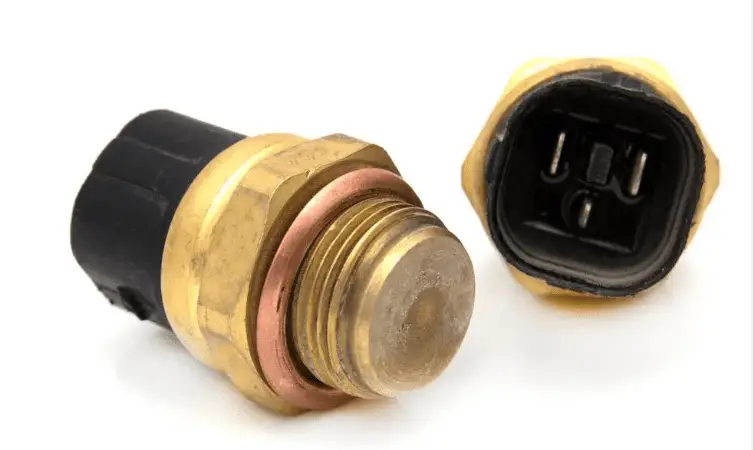
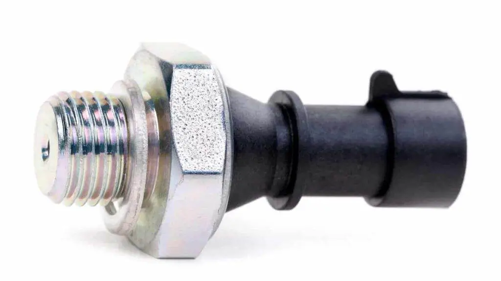
Common symptoms of a faulty engine oil pressure sensor
The purpose of the engine oil pressure sensor is to measure the amount of oil pressure in your car to optimize fuel injection, ignition timing, and other critical engine parameters. This sensor plays a crucial role in your engine, so what are the common signs of a faulty engine oil pressure sensor? Let’s explore the potential causes of its failure and the implications this can have on the vehicle’s operation.
What Does the Oil Pressure Sensor Do in Your Car?
The oil pressure sensor, also known as the oil pressure switch, primarily functions to monitor the oil pressure in the car’s engine and sends data to the ECU or the instrument cluster. From there, the driver can easily know the amount of fluid pumped into the system. If the oil is pumped correctly, it will provide good lubrication, reduce friction, and dissipate heat. Depending on the pressure level, the ECU will send a signal to illuminate the warning light on the dashboard so the driver is aware and can take timely action.
It is clear that the oil pressure sensor has two obvious functions:
Ensure the engine receives adequate oil pressure for proper lubrication.
This sensor serves as a safety device by warning the driver if the oil pressure drops below a certain threshold.
So, where is the oil pressure sensor located in your car? The oil pressure sensor is typically located near the engine’s oil pump or on the engine block, and it is connected to the engine control unit (ECU) or the instrument cluster.
If a problem occurs with this sensor, the ECU cannot do a good job of controlling the engine. (Photo: mechanicbase.com)
3 Symptoms of a Faulty Oil Pressure Sensor to Know
As an important element of the car’s sensor system, directly affecting your car’s starting and acceleration process, the oil pressure sensor needs to function correctly. If a problem occurs with this sensor, the ECU cannot do a good job of controlling the engine. A malfunction in oil pressure can manifest through various signs. Here are the symptoms of the oil pressure sensor:
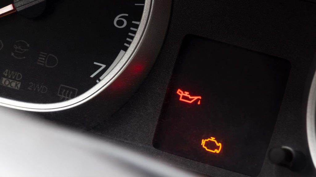
Oil Pressure Sensor Warning Light
One of the most obvious indications is the illumination of the oil pressure warning light on the car’s dashboard. This light usually resembles an oil can or an oil drop. If the light comes on but the engine oil is still at the standard level, the cause might be a faulty sensor. If this sensor malfunctions, the results obtained will be inaccurate. In some cases, it also indicates that the oil pressure has dropped below the recommended level.
Errors in the Oil Pressure Gauge
Currently, most new cars are equipped with an oil pressure gauge on the dashboard to provide drivers with information about oil pressure. If you detect that the gauge indicates a very low oil pressure level or fluctuating values, it means the oil pressure system is faulty. This affects the system’s operation, reducing the accuracy of the displayed results. This is one of the common signs of a problem with the oil pressure sensor. Please note that a properly functioning oil pressure gauge should display stable pressure within the normal range. Any deviation from the normal reading may indicate a problem.
Check Engine Light
The engine control unit (ECU) monitors various sensors, including the oil pressure sensor, to ensure the engine operates within optimal parameters. If the ECU detects a problem with the oil pressure sensor, it may trigger the “Check Engine” light to alert the driver of a potential issue.
When the oil pressure sensor malfunctions, it may send incorrect signals or no signal to the ECU. As a result, the ECU may interpret this as an engine oil pressure problem and trigger the “Check Engine” light.
However, the “Check Engine” light can illuminate for various reasons, so it’s best to entrust the diagnosis to trusted mechanics to retrieve the specific error codes stored in the ECU.
If the diagnosis confirms that your oil pressure sensor is faulty, you can apply several methods:
Monitor the engine oil pressure: Ensure the oil pressure readings are within the normal range.
Check the oil level: Inspect that the engine oil level is within the recommended range.
Replace the oil pressure sensor if necessary.
Symptoms of a faulty oil pressure sensor (Photo: repairsmith.com)
How to Replace a Faulty Engine Oil Pressure Sensor?
Replacing with a new oil pressure sensor is the recommended method if this sensor has a problem. Here is a general step-by-step guide for changing the oil pressure sensor that you can refer to if you have a faulty one:
Step 1: Prepare the Necessary Tools
Before starting the process, the car owner should gather the necessary tools for the job, such as a set of screwdrivers, a soft towel, specialized sealant, and a set of wrenches.
Step 2: Locate the Sensor
Depending on the vehicle’s engine design, type, and structure, the location of the pressure sensor on each car may differ. Generally, this sensor is installed near the bottom of the cylinder head, inside the engine block, or near the oil pump. You can read the owner’s manual to find the exact position of the sensor.
Step 3: Disconnect the Car Battery
To prevent any electrical accidents, disconnect the negative terminal of the vehicle’s battery. In the next step, you need to carefully disconnect the electrical connector from the oil pressure sensor. You may need to press or squeeze a locking tab to release it.
Step 4: Remove the Oil Pressure Sensor
Next, the driver should use a wrench or socket to remove the oil pressure sensor to inspect and determine the cause of the damage. The oil pressure switch is installed where there is pressurized oil, so repairers must be extremely careful when doing this. Take note of any sealing washers or O-rings that might need replacement.
Step 5: Replace it with a New Sensor
After completing all these steps, proceed to install the new sensor in the correct position and tighten it. Then, install the electrical connector after tightening it with a wrench. Secure the electrical connector to the new oil pressure sensor, ensuring a secure connection. Finally, the car owner simply needs to start the engine and observe the oil pressure indicator to ensure the sensor is functioning stably again. Additionally, check for any oil leaks around the sensor area.
When the engine is running, oil pressure is typically between 2.5 and 4 kg/cm² (depending on the vehicle model). At idle, the pressure level is usually below 0.5 kg/cm². Normal oil pressure always remains stable at this level. Low oil pressure indicates that the amount of oil in the system is not sufficient for lubrication, leading to high engine friction and rapid engine wear. Not addressing this issue in time can result in vehicle overheating, loud noises, and damage to components such as the crankshaft.
How to Check if an Oil Pressure Sensor is Working?
If you have access to an oil pressure gauge, you can perform a manual oil pressure test. This involves removing the oil pressure sensor and connecting the gauge in its place. Start the engine and check the oil pressure on the gauge. Compare the reading to the specifications provided in the vehicle’s manual. If the reading is significantly different or inconsistent, it may indicate a problem with the sensor or the oil system.
Another method you can try is using a multimeter: Set your multimeter to the resistance setting (ohms). Connect the multimeter probes to the terminals of the oil pressure sensor. Specific resistance values vary depending on the sensor and engine specifications. Consult the vehicle manual for the expected resistance range. If the resistance falls outside the acceptable range, it may indicate a faulty sensor.
Can a Faulty Oil Pressure Sensor Cause an Oil Leak?
A faulty oil pressure sensor or other components associated with the oil pressure system can develop leaks. If you notice puddles or drops of oil under the vehicle or detect a burning oil smell, it could indicate an oil leak caused by poor oil pressure. Another case is if the oil pressure sensor is not properly tightened during installation or if the sealing washer or O-ring associated with the sensor is damaged or worn, it can result in an oil leak around the sensor area.
Symptoms of a Slipping Clutch (What It Means and How to Fix It)
Has your manual transmission car started feeling a bit strange when you shift gears? Do you notice the engine revving higher than normal before the car moves? A slipping clutch could be the cause, and it will only get worse over time.
Knowing how to identify the distinct symptoms of a slipping clutch early can help you anticipate bigger problems and avoid a breakdown on the road.
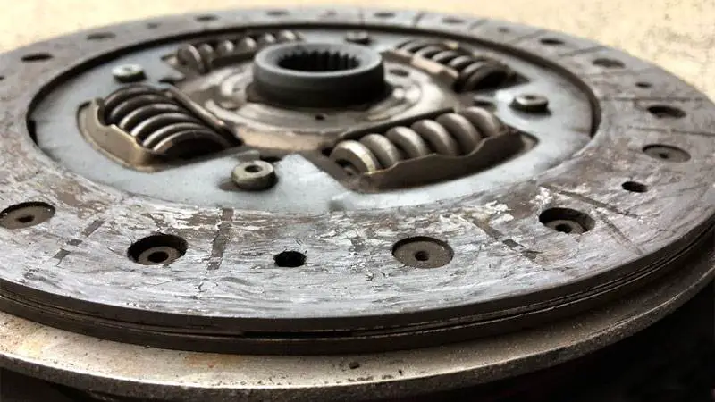
What Does It Mean When a Clutch Slips?
A clutch is designed to maintain a certain level of engine torque, typically measured in foot-pounds (lb-ft) or newton meters (N·m). A pressure plate is used to hold the clutch against the flywheel, causing the transmission input shaft and engine to spin at the same speed.
Clutches are designed with friction material on both sides that will grip the surfaces of the metal pressure plate and flywheel. As a clutch wears out, it loses this friction material, much like your brake pads would.
At some point, the clutch will no longer hold the same torque as before. When engine torque exceeds the maximum torque a clutch can handle, the clutch begins to slip intermittently under higher engine loads.
Instead of gripping the flywheel and pressure plate, a worn clutch will allow the engine to spin freely, even when the clutch pedal is fully released. This phenomenon is often more noticeable in a mid-range gear, such as third or fourth, and will gradually worsen over time until the clutch is replaced.
In extreme cases, a worn clutch can leave you stranded, as the vehicle will not be able to transmit engine power to the ground.
This condition is often seen in vehicles that frequently drive in heavy traffic, cars with newer drivers, high-performance vehicles that are driven hard, and cars equipped with upgraded engines that far exceed their factory power level.
If any of these conditions apply to you, don’t be surprised if you experience slipping issues with your clutch.
Top 5 Symptoms of a Slipping Clutch
It’s important that you notice a slipping clutch before it causes serious problems for you or your vehicle. You wouldn’t want the engine to disengage from the drive wheels while driving at high speed. That could potentially cause an accident.
So try to recognize the symptoms of this issue so you can work on modifying your driving habits and fixing the problem. Here are five common ways to tell if the clutch is slipping.
1) RPM Increases But Not Speed
A simple way to test if you have a slipping clutch is to take note of your engine RPM. If you press the accelerator pedal to accelerate and your RPM increases faster than normal while your driving speed does not increase as it should, you likely have a slipping clutch.
For example, you might be driving on the highway and decide you need to pass a slower vehicle. When you try to accelerate, your RPM increases and your engine makes more noise, but your car doesn’t go any faster. A slipping clutch is usually more obvious in higher gears when you try to accelerate.
2) Burning Smell
When the clutch slips, a burning smell emanates from the front of the car. This is due to all the excess heat generated by the constant disengagement of the engine and the slipping of the clutch.
The more the clutch slips, the worse the burning smell becomes. You don’t want to drive with this smell in the cabin as it will make you nauseous. The more the clutch slips, the more the situation deteriorates.
3) Poor Engine Performance
The ultimate test occurs when you’re pulling a heavy load in or behind your vehicle. Normally, this would require the engine to send a lot of power to the drive wheels.
But if your clutch is slipping, the engine won’t be able to deliver that power. Then you’ll have almost no acceleration due to this lack of engine power. You can reduce the load you’re pulling to increase power somewhat, but it won’t be a permanent solution.
4) Clutch Pedal Height Difference
When driving your vehicle, you should be accustomed to the height of the clutch pedal relative to the floor. When you press the pedal and remove your foot, the pedal should always return to the same height as before.
If you ever notice the height starting to change, whether the pedal is too high or too low, then something is definitely wrong with the clutch. In most cases, this will be due to the clutch slipping.
You can try adjusting the clutch pedal to see if it helps, as this is much cheaper and easier than dropping the transmission to replace the clutch.
5) Quick Disengagement
The main symptom of a slipping clutch is quick disengagement between the engine and the drive wheels. When the clutch is normal, you’ll need to press the pedal about 1 to 2 inches before the engine disengages.
However, with a slipping clutch, the engine will disengage after lightly pressing the clutch pedal less than an inch. Sometimes, just resting your foot on the pedal will cause the engine to disengage.
How to Fix a Slipping Clutch?
Flywheel surface after driving with a bad clutch for too many miles.
There is virtually only one solution to fix a slipping clutch: clutch replacement.
Sometimes, a rear main seal leak will cause a good clutch to slip (because the clutch can be lubricated with engine oil), but usually you’ll just replace the clutch while you’re at it; the mechanic has to drop the transmission anyway to replace the rear main seal, and the parts cost for a clutch job isn’t very high.
You’ll also want to consider resurfacing or replacing the flywheel and pressure plate, as these parts can degrade over use. If the clutch is worn down to the rivets, there’s a good chance the excessive heat and metal-on-metal contact has damaged the flywheel and warrants its replacement.
What Causes a Clutch to Slip?
There are a variety of factors that can cause your clutch to show signs of slipping, including driving styles and shifting habits. Here are the most common causes:
Worn Clutch Disc
Over time, the friction material on the clutch disc can wear out. This reduces the disc’s ability to grip the flywheel and pressure plate, allowing it to slip when torque is applied via the transmission.
Riding the Clutch
Resting your foot on the clutch pedal while driving puts constant pressure on the clutch. This can cause overheating and slipping. It’s best to press the clutch fully when shifting gears, then release it completely.
Weak Clutch Springs
The clutch disc is clamped between the pressure plate and flywheel by springs. If these springs weaken or break, they won’t apply enough force to prevent slipping.
Launching from a Stop
Quickly releasing the clutch and trying to accelerate aggressively from a stop puts a lot of stress on the clutch components. This can lead to premature wear and slipping. Of course, burnouts can be fun, but they have consequences.
Low Clutch Fluid Level
Clutches use hydraulic fluid to engage and disengage. If the fluid level is low, the pressure plate may not fully engage the clutch disc.
Oil Contamination
Oil or grease on the clutch disc can prevent it from gripping properly. A rear main seal leak could cause oil contamination of the clutch.
Overheating
Excessive heat buildup, due to heavy loads or riding the clutch, can glaze the clutch disc material, reducing grip. This is commonly referred to as clutch discoloration.
Poor Shifting Habits
Not fully depressing the clutch when shifting, shifting into the wrong gear, or releasing the clutch too quickly can cause the clutch to slip as it tries to match the speeds of the engine and transmission.
Improper Downshifting
When downshifting, the engine RPM should be increased to match the lower gear ratio before releasing the clutch. If the clutch is released before the engine RPM increases, the clutch will slip.
Towing or Carrying Heavy Loads
Using the clutch to start from a stop with a heavy load in the vehicle can cause overheating and slipping over time. The load puts extra strain on the clutch.
Preventing Future Clutch Slippage
To prevent clutch slippage on the road, start by regularly checking your clutch fluid. Low levels can cause slipping, so keep it filled with the factory-specified fluid.
Also focus on smooth driving. Avoid aggressive launches or reckless shifting that can prematurely wear out the clutch. Instead, be gentle with the pedal and perform deliberate shifts.
Also stay on top of maintenance. Have a mechanic inspect the clutch system during routine visits. Early detection of any issues can prevent slipping.
When the time comes, invest in a quality replacement clutch rather than opting for the cheapest option. A robust replacement kit will provide better grip and longevity.
FAQ
Can the Clutch Slip in an Automatic Transmission?
Although automatic transmissions don’t have a manual clutch, they can still experience slipping issues similar to manual vehicles. Instead of a clutch, automatic systems use a torque converter and transmission fluid pressure to shift gears, so issues such as low fluid levels or a faulty torque converter can cause gear slippage.
Just like inspecting the clutch on a manual transmission, it’s important to regularly check the transmission fluid and address any slipping issues promptly in an automatic transmission. With proper maintenance and care, slipping can be avoided in both types of transmissions.
Slipping vs Riding the Clutch: What’s the Difference?
When you experience a slipping clutch, it means the clutch is not properly transferring engine power to the transmission. This causes the engine to rev faster than it should, while the car doesn’t go any faster. You’ll typically notice an increase in RPM without a corresponding increase in speed, along with a foul burning smell or a feeling of disconnection between the accelerator pedal and acceleration.
On the other hand, riding the clutch is a bad driving habit where you constantly keep your foot on the clutch pedal, even when it’s not necessary. This could lead to faster clutch wear, which might contribute to its slipping in the long run. Avoid riding the clutch by releasing the pedal between shifts or when you’re not actively using it to maintain clutch integrity.
Why Is My Brand New Clutch Slipping at High RPM?
There are several reasons why your new clutch might be slipping at high RPM. First, the clutch may not have been broken in sufficiently yet. It’s important to allow your new clutch time to wear in properly, which may require 500 to 1,000 miles of easy driving. Avoid aggressive acceleration and high RPMs during this period.
Faulty installation could be another reason. In some cases, improper alignment or incorrect torque settings can lead to excessive wear or poor clutch performance.
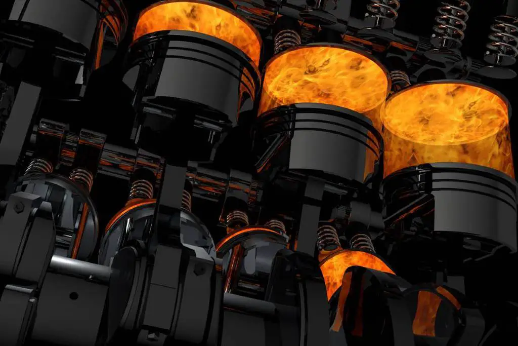
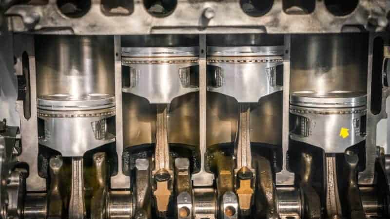
4 cylinders vs 6 cylinders – What are the differences
When purchasing a vehicle, whether it’s a new Mercedes-Benz or a used Toyota Camry, you need to understand the type of engine it has and how it is better or worse than other types. The most popular categories are four and six cylinders. Having a thorough knowledge of 4 cylinder vs. 6 cylinder will help you make an informed purchase decision.
What is a 4-cylinder engine?
A four-cylinder car engine is a type of internal combustion engine with four cylinders arranged in a straight line, V-shape, or horizontally opposed configuration. Each cylinder contains a piston that moves up and down, converting the energy from fuel combustion into rotational energy that drives the vehicle’s wheels through the transmission.
Four-cylinder engines are commonly used in smaller, more fuel-efficient cars because they are lighter, more compact, and require less fuel than larger engines with more cylinders. They can also be designed to produce high levels of power and torque, making them suitable for performance-oriented vehicles as well.
Despite these advantages, 4-cylinder engines still have some drawbacks: higher emissions and lower efficiency when driving at low speeds.
A 4-cylinder engine. (Photo: ViewTech)
What is a 6-cylinder engine?
6-cylinder engines have the same displacement, all else being equal, as 4-cylinder engines. A 6-cylinder engine has 6 pistons inside the engine mechanism. However, there are differences between an inline six-cylinder engine and a V6 engine. The former offers excellent driving balance and easier access for maintenance, while the latter is more compact and better suited for front-wheel drive applications. Nowadays, supercars are full of V6 engines. You’ll find them in public favorites like the Acura NSX, Nissan GT-R, and more. Like other types of engines, 6-cylinder engines also have advantages and disadvantages:
Advantages:
Power: Six-cylinder engines tend to produce more power and torque than four-cylinder engines, which can provide better acceleration and towing capabilities.
Smoothness: Six-cylinder engines generally run more smoothly than four-cylinder engines because they have more cylinders firing in sequence, which can result in less vibration and noise.
Refinement: Many six-cylinder engines are designed with advanced technologies such as variable valve timing and direct injection, which can improve fuel efficiency and reduce emissions.
Performance: Six-cylinder engines are often used in high-performance and luxury vehicles because they can offer a balance of power, smoothness, and refinement.
A 6-cylinder engine. (Photo: Which Car)
Disadvantages:
Fuel Economy: Six-cylinder engines tend to consume more fuel than four-cylinder engines, which can lead to higher operating costs.
Cost: Six-cylinder engines are generally more expensive to manufacture than four-cylinder engines, which can increase the vehicle’s cost.
Weight: Six-cylinder engines are typically larger and heavier than four-cylinder engines, which can affect the vehicle’s handling and balance.
Maintenance: Six-cylinder engines may require more maintenance than four-cylinder engines, including more frequent oil changes and tune-ups.
4 Cylinder vs. 6 Cylinder – The Differences
The number of cylinders only refers to the number of pistons inside the engine. So, when trying to understand the concept of 4-cylinder and 6-cylinder engines, the first thing you need to understand is that the different names refer to the number of cylinders. However, this difference in the number of cylinders also influences performance factors.
Performance
Six-cylinder versions are more powerful than their four-cylinder counterparts. They are larger, faster, and better suited for race cars. The four-cylinder engine is smaller and cannot produce as much power. However, modern 4-cylinders have more power than their predecessors due to technological advancements.
For example, an old 6-cylinder from a 2007 Hyundai produces 185 horsepower. You’ll get the same power from a Hyundai Santa Fe Sport with a 2.0-liter engine. The turbocharged model can provide even more power – 240 horsepower. So, it’s always better to buy a new 4-cylinder rather than an old car model equipped with a 6-cylinder engine.
A 2014 Porsche Cayman S with a 6-cylinder engine. (Photo: Teslamotors.com)
Fuel Consumption
A four-cylinder will always be an economical purchase because it consumes less fuel and is suitable for smaller cars. If you don’t imagine yourself as Michael Schumacher every time you drive on an empty highway, buy a 4-cylinder car and save a significant amount on your car budget.
Carbon Dioxide Emissions
If you are thinking about the environment and are conscious of your carbon footprint, a hybrid car is the best option. But if the budget doesn’t allow it, buy a 4-cylinder car instead. It’s a good alternative since it emits fewer pollutants into the air. The turbocharged version offers even better fuel efficiency and lower carbon emissions.
Applications
Six-cylinder models are better suited for vehicles with larger engines because the extra power makes it easier to move their heavy structures. In contrast, smaller, more compact cars use 4-cylinders.
To learn more about the differences between 4-cylinder and 6-cylinder engines:
The choice between a 4-cylinder engine and a 6-cylinder engine depends on various factors such as the intended use of the vehicle, performance requirements, and fuel efficiency goals. Four-cylinder engines are generally lighter, more compact, and more fuel-efficient, making them suitable for smaller, more economical cars. On the other hand, six-cylinder engines typically offer more power, smoother operation, and better towing capabilities, making them suitable for larger, higher-performance vehicles. Ultimately, the decision depends on your personal preferences, and it’s essential to consider all factors before making a choice.
Common Symptoms and Causes of Engine Misfires
You are experiencing engine stalling, rough rides, loss of engine power, and unusual smells and noises coming from your engine. These are common symptoms of engine misfires, which occur when one or more components necessary for engine combustion deviate from their intended operation.
Engine misfire symptoms should not be ignored, as a misfiring engine will underperform and may be damaged over time, even if you might be able to drive for a while.
Your car will also experience reduced fuel economy and increased emissions, as the engine is forced to work harder to compensate for the cylinder(s) that are not functioning properly.
Learn how engine misfires occur, the common symptoms and causes of engine misfires, and how much it costs to repair a misfiring engine.
What a Misfire Feels Like and How It Happens
To better understand the symptoms and causes of engine misfires, you must first understand how a car’s engine works. The basics of engine operation will set the stage for explaining how it can misfire.
The engine block houses the engine cylinders, inside which the pistons move up and down, creating energy. The more cylinders an engine has, the more powerful it is. Engines typically have four, six, or eight cylinders.
A precise mixture of fuel and air is injected into the cylinder. The spark ignites, creating a small combustion or explosion that forces the piston down successively inside each cylinder.
This happens in each cylinder at slightly different times and at a precise moment. The energy generated by the combustion is transferred to the wheels via the crankshaft, which propels the car forward.
The entire process requires strict precision for the engine to function correctly. Even a slight deviation in one component would impact engine performance.
A misfire is what happens when one of the three components – fuel, oxygen, or spark – does not function at the right time. For example, if the air-fuel ratio is incorrect, the mixture may not burn at all or may explode prematurely.
A misfire is what happens when fuel, oxygen, or spark do not function at the right time. (Photo: VEHQ)
Besides this incorrect timing, the problem can also come from the mechanical components of the system, such as the cylinder itself.
A misfire does not necessarily mean your car will stop running, and if only one cylinder is misfiring, the others may continue to operate normally. However, you will notice a significant slowdown in your engine’s operation.
Most Common Engine Misfire Symptoms
Loss of Power
There can be a palpable loss of power resulting from a vehicle running with fewer cylinders than normal. Another symptom is a brief hesitation in power delivery when you press the accelerator pedal.
Engine Noises
One of the most common engine misfire symptoms is a very noticeable noise coming from your engine. If you are familiar with the usual sounds of automobiles, you will notice when an abnormal sound occurs.
During a misfire, the engine will emit a sudden noise that can be described as a popping, sneezing, or backfiring sound.
A backfire occurs when unburned fuel exits the cylinder during the exhaust stroke, is then ignited further in the system by the spark from the next cylinder, and explodes loudly out of the exhaust system.
Otherwise, you might notice an overall change in the engine noise if a cylinder is not working at all, since a four-cylinder car will now only have three functioning cylinders.
There are certain signs of misfires that you need to keep in mind. (Photo: Mechanic Rx)
Unusual Smell
Damaged cylinder walls can sometimes cause fluid leaks, leading to a smell primarily of gas with hints of oil or coolant.
The smell of burning coolant will be somewhat “sweet.” This one is harder to pinpoint because different types of misfires can lead to different leaks that result in different smells.
Unusual Exhaust
When engine misfires prevent fuel from burning properly or mixing correctly, you will notice excessive exhaust gases.
This can also occur when you have leaks causing compression issues that lead to coolant or oil mixing into the combustion reaction.
Anything in the combustion chamber other than air or gasoline will affect the vehicle’s ability to burn the mixture as intended.
Your exhaust may be unusually thick or sometimes bluish if there is oil burning during combustion. Dark, sooty exhaust gases could indicate a rich air-fuel mixture or carbon buildup.
Engine Stalling
Misfires can sometimes lead to difficulty starting the vehicle or the engine stalling while idling. Stalling happens most often at idle but can eventually occur even while driving, which would be particularly dangerous.
Engine stalling is even more likely when you put a strain on the engine with a high accessory load, for example, when waiting at a red light with the air conditioning, headlights, and radio on.
Misfires can sometimes lead to difficulty starting the vehicle or the engine stalling while idling. (Photo: JD Power)
Rough Ride
Cars are now equipped with shock absorbers and other technologies designed to minimize the feeling of bumps on the road or the engine’s rumble. One of the common engine misfire symptoms, even when only one cylinder is misfiring, is a noticeably shaky ride.
Excessive vibrations while the vehicle is moving are common, especially if the misfires are caused by a mechanical issue. The severity varies depending on the RPM and is often worse at idle.
Rough Acceleration
If your car shakes during acceleration but not at idle, you are likely facing an engine misfire. Acceleration puts pressure on the engine, and a misfiring engine will struggle with this task because it is not operating under optimal conditions.
Poor Acceleration
You can experience both rough acceleration and poor acceleration with an engine misfire.
When the air/fuel ratio deviates due to a faulty O2 sensor, the mixture can be too rich or too lean in fuel. On some models, this will trigger something called “limp mode.”
This is a safety feature that allows you to safely get off the road if there is a problem with the engine, which will significantly limit acceleration. A car going into limp mode is also a common symptom of engine over-revving.
You can experience both rough acceleration and poor acceleration with an engine misfire. (Photo: dubizzle)
Check Engine Light
This is a rather vague indicator of what is wrong; however, note that the Check Engine light will come on and off when your engine is misfiring. This is one of the few engine problems that cause this, as others usually cause the light to come on and stay on.
What Causes a Misfire in Cars?
What causes a car to misfire? An engine relies on three elements to ignite the cylinder: an adequate amount of fuel, oxygen to burn the fuel, and a spark for ignition. The inadequacy or absence of any of these elements will result in engine misfires.
Other possible reasons could be vacuum leaks, incorrect ignition timing, and a worn valve spring. Let’s discuss some engine misfire symptoms and their causes!
1. The Ignition System
Ignition parts, including spark plugs, ignition wires, and coils, wear out or corrode over time. They have a specific lifespan and need to be replaced beyond that duration.
When one or more of these parts begin to wear out, there comes a point where the spark plugs no longer receive enough electricity to create sparks.
Worn spark plugs could be the cause. (Photo: Healthcare)
This will start with brief intermittent misfires and worsen over time. However, most ignition system components are inexpensive and easy to repair.
2. Check Fuel System Components
If the problem is not from the ignition system, you should next check the fuel system parts.
These components also wear out, but at a slower rate. Look for a clogged fuel filter, dirty fuel injectors, and a faulty mass airflow sensor or fuel pump. The EGR valve could also stick if not cleaned for a long time.
If that is the case, it will allow exhaust waste to enter the intake manifold and create engine misfires. Most problems can be fixed by cleaning or replacing the problematic part.
3. Damaged Cylinder Walls
A misfiring engine creates popping sounds or sneezes. Sometimes there is also a distinct smell, which is a mixture of gasoline, coolant, and vapor.
Such a strong smell is a warning sign indicating damaged cylinder walls. You should take the car to a mechanic to inspect the engine as soon as possible.
Take the car to a mechanic if the problem persists. (Photo: Repairer)
Is It Safe to Drive When an Engine Is Misfiring?
Usually, the vehicle can continue to drive with misfires in one cylinder, since the others will keep the car moving. However, it will not function normally, and it could get worse over time.
Ignoring the problem for too long can damage engine parts such as the catalytic converter and oxygen sensor.
Also consider the safety issue when the car loses power and stalls in the middle of a busy road. A misfiring engine also increases emissions and decreases fuel efficiency.
Cost to Repair a Misfiring Engine
If you are lucky, a simple spark plug change can sometimes cost you only a few dollars if you can do it in your own garage.
Other times, you may need a major replacement for your engine misfire symptoms, among which is changing a fuel injection system at the mechanic.