Isolation fault in electric vehicle

Insulation faults in electric vehicles can pose a significant risk to user safety and the reliability of electrical systems. This article explores the different types of insulation faults, their impact, and the methods for checking them using a megohmmeter.

Types of Insulation Faults

1. Insulation Faults to Ground

This type of fault occurs when one of the conductors comes into contact with the ground, which can lead to current leakage.

We want to check for insulation above 80 MΩ.
After verifying the complete absence of voltage, we measure the resistance between a 400 V DC phase and the
ground. The ohmmeter we are using displays out of range 'OL'. It has reached its maximum measurement range. We
will then use an insulation tester.

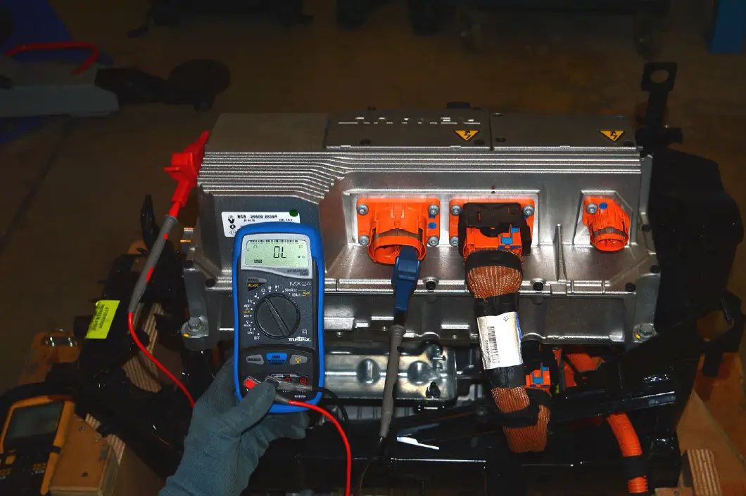
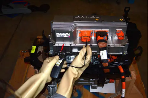
Below is an example showing a case where the ohmmeter is no longer able to perform the measurement. We
want to check for insulation above 80 MΩ. After verifying the complete absence of voltage, we measure the resistance between a 400 V DC phase and the ground. The ohmmeter we are using displays out of range ‘OL’. It has reached its maximum measurement range. We will then use an insulation tester.

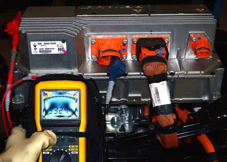
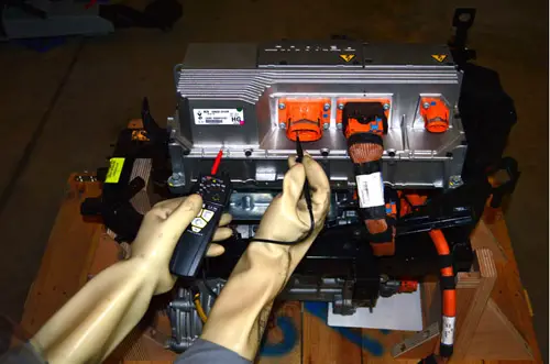
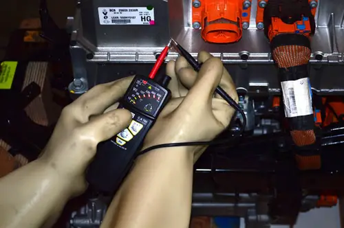
The insulation tester displays a resistance value of 3,324 M when we measure the resistance between a phase and the ground on a component. For a part to be declared compliant, the measured resistance must be greater than the minimum value specified by the manufacturer in the diagnostic manuals.

2. Faults Between Conductors

These faults involve a reduction in the insulation resistance between two conductors, increasing the risk of a short circuit.

3. Aging or Degradation of Insulating Materials

Over time, insulating materials can lose their effectiveness due to environmental factors such as heat, moisture, or vibrations.

Impact of Insulation Faults

Insulation faults can cause:

  • Risk of electrocution for users.
  • Degradation of the vehicle’s electrical performance.
  • Increased risk of fire.
  • Systemic failure of electrical equipment.

Checking Methods with a Megohmmeter

Principle of the Megohmmeter

The megohmmeter is a device used to measure insulation resistance by applying a high voltage between the conductors and/or the ground. It provides a value in megaohms (MΩ), indicating the state of the insulation.

Checking Steps

  1. Preparation:
    • Disconnect the equipment to be tested from the circuit.
    • Ensure the system is de-energized.
  2. Connecting the Megohmmeter:
  3. Applying the Voltage:
    • Set the voltage recommended by the manufacturer (usually between 500V and 1,000V).
    • Start the measurement.
  4. Reading the Results:
    • A resistance below the minimum limit indicates an insulation fault.

Illustration of the Steps

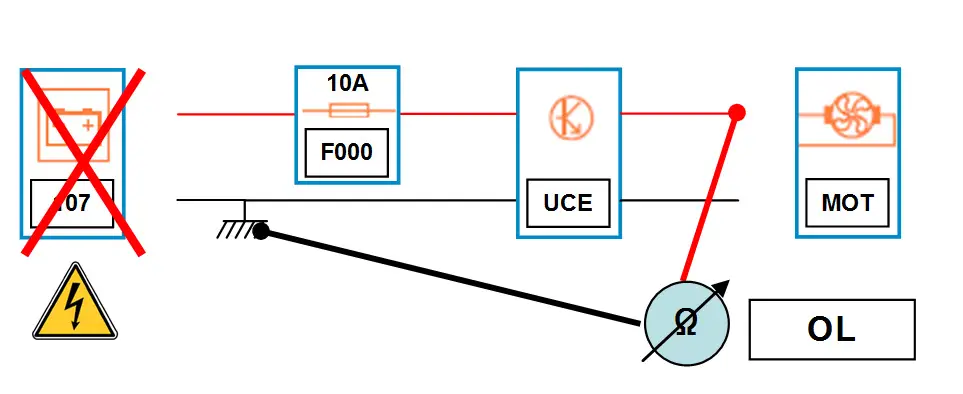
A ground insulation check involves verifying that an element, receiver, or conductor is not touching the ground.
With an ohmmeter, we measure with the power off:

  • If R = “OL” (Out of Limit: infinite), between the controlled line and the ground, the ground insulation check may be
    correct.
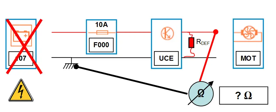
    Caution: an out-of-limit resistance is indicated by “OL”, meaning the resistance is higher than what
    the device can measure. For circuits powered by the traction battery of an electric vehicle, it will be necessary to
    refer to the minimum reference resistance required in the diagnostic manuals.
  • 107: 12V battery
  • F000: fuse
  • UCE: control unit – Electronic Control Unit
  • MOT: Electric motor
  • If, for example, R = ? Ω (Ohm), there is a short circuit to “ground”.

A mutual insulation check involves verifying that two or more wires are not touching each other.
This operation must be repeated as many times as there are wires in the implicated harness.
With an ohmmeter, we measure with the power off:

  • If R = OL (infinite) between these two wires, the circuit is compliant.
  • If R = ? Ω (Ohm), there is a mutual short circuit.
    Search with an insulation tester
    An insulation check involves verifying that an element, receiver, conductor, or ground is not touching.
    With an insulation tester, we measure the insulation between a power cable and the ground, or between two power cables, with the power off, to check for short circuits and insulation faults.

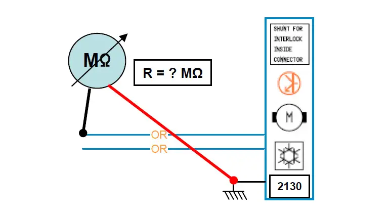
2130: air conditioning compressor
To interpret the measurement, it will be necessary to refer to the minimum reference value required in the diagnostic manuals.

  • If R > “reference value” MΩ, the circuit is compliant.
  • If R ≤ “reference value” MΩ, the circuit is non-compliant.

Check for the absence of voltage between the phases and the ground and between the phases (3 measurements).

Check the proper functioning of your voltage absence verification device.

  1. Do not test a vehicle or equipment when it is located in a flammable or
    explosive environment. Sparks may occur during the discharge of the insulation before and after the test or during the test in case of faulty insulation.
  2. Restrict personnel access as much as possible by marking the area and wearing personal
    protective equipment for electricians. During measurement, there may be high measurement voltages,
    exceeding safe voltages for persons.
  3. Use only connection cables suitable for the test to be performed and ensure they are in perfect condition. Unsuitable cables will lead to measurement errors and can be dangerous.

The measurement

  1. Turn on the device by setting the switch to the M position and selecting the desired voltage
    (50 V, 100 V, 250 V, or 500 V).
  2. Check that all displays are functioning and that the battery charge level is correct.
  3. The determination of test voltages is based on the operating voltage of the devices. The table below
    gives the recommended test voltages based on the operating voltages of installations and
    equipment.
Operating voltage
cable / equipment
DC test voltage
24 to 50 V 50 to 100 V
50 to 100 V 100 to 250 V
100 to 240 V 250 to 500 V
240 to 550 V 500 V

It is required to use the electrical and electronic diagnostic manuals to know the recommendations for the test voltages to be applied.

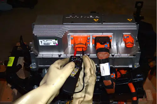
Check between a conductor and the ground or earth. To do this, connect the cable from the “+” (plus) terminal of the insulation tester to the cold point and the one from the “–” (minus) terminal of the insulation tester, or the remote control probe, to the hot point. Alligator clips are preferable to handheld probe tips.
By this we mean:

  • Cold point: neutral, earth, ground.
  • Hot point: a phase. The insulation tester measures and displays the presence of voltage between its terminals as soon as it is turned on. Before starting the insulation measurement, verify that there is no voltage present on the terminals to be checked.
  • If the voltage on the vehicles is greater than 25 V, a warning display is indicated and/or a continuous signal
    is given, the measurement is not possible. Do not perform an insulation or resistance measurement when
    the presence of a voltage is indicated.
  • If the voltage present on the vehicles to be checked is less than 25 V, the insulation measurement is possible,
    but it is affected by an error that is more significant the lower the test voltage. It is required to have a voltage close to 0 V.
  • If there is no dangerous voltage, the user can then perform an insulation measurement.
  1. Press the “TEST” button,

The Basics of ECU Reprogramming: What You Need to Know Before Starting

The ECU (Engine Control Unit) is the electronic “brain” of your vehicle. It controls several engine parameters, such as fuel injection, ignition timing, and even power limits. ECU reprogramming involves modifying the embedded software to improve vehicle performance, reduce fuel consumption, or correct certain factory defects.


Why Reprogram an ECU?

  1. Performance Improvement: Increase power and torque by optimizing settings.
  2. Fuel Economy: Adapt parameters for more efficient driving.
  3. Adaptation to Mechanical Modifications: Adjust settings after modifications such as adding a turbo, installing a sports exhaust, or changing the air filter.
  4. Error Correction: Resolve software issues or bypass limitations imposed by the manufacturer.

Required Tools

Before starting, you need to have certain equipment:

  • Reprogramming Software: For example, WinOLS, ECM Titanium, or Alientech KESS.
  • ECU Read/Write Tool: Such as KESSv2, K-TAG, or MPPS.
  • A Laptop with a compatible operating system.
  • A Voltage Stabilizer: To prevent electrical interruptions during reprogramming.
  • An ECU Backup File: Always back up the original file before making any modifications.

What to Know Before Starting

  1. Technical Knowledge: Understanding the basics of engine and ECU operation is essential. A mistake can cause irreversible damage.
  2. Vehicle Compatibility: Check that the tool and software are compatible with your car model.
  3. Associated Risks: Poor programming can lead to mechanical problems, overheating, or loss of warranty.
  4. Legality: In some countries, ECU reprogramming may be illegal or subject to restrictions. Ensure you comply with local regulations.

Basic Steps to Reprogram an ECU

  1. Connection: Connect the OBD-II diagnostic tool to the ECU via the vehicle’s OBD port.
  2. Data Reading: Download the ECU’s original file to your computer.
  3. Parameter Modification: Use software to adjust fuel maps, turbo pressure, or ignition settings.
  4. Writing: Load the modified file into the ECU.
  5. Testing: Perform road tests to ensure everything is working correctly.

Tips for Beginners

  • Start with online tutorials or training to learn how to use the tools.
  • Avoid extreme modifications, as they could damage the engine.
  • Always work in a clean and stable environment without electrical interruptions.
  • Keep a copy of the original file to revert if necessary.

Conclusion

ECU reprogramming is a powerful method to customize and optimize a vehicle. However, it requires technical skills, specialized tools, and great attention to detail. If you are a novice, consider seeking assistance from a professional or taking training courses before starting.

New EV Battery Technologies and Their Impact on Automotive Maintenance

Electric vehicles (EVs) are evolving rapidly, largely due to innovations in battery technologies. These advancements are not only transforming vehicle performance but also how maintenance is approached. Here is an overview of new EV battery technologies and their impact on automotive maintenance.


1. New EV Battery Technologies

a. Advanced Lithium-Ion Batteries
  • Improvements in energy density and lifespan.
  • Introduction of new chemistries, such as lithium-nickel-manganese-cobalt (NMC) and lithium-iron-phosphate (LFP).
  • Impact: Longer range and faster charging cycles, with less degradation over time.
b. Solid-State Batteries
  • Replacement of liquid electrolyte with a solid material.
  • Advantages: Enhanced safety, higher energy density, fast charging.
  • Impact: Reduced risk of overheating, lowering maintenance needs related to thermal management systems.
c. Lithium-Sulfur Batteries
  • Use of less expensive and more abundant materials.
  • Promise of very high energy density.
  • Impact: Less maintenance for managing critical resources like cobalt or nickel.
d. Recyclable and Sustainable Batteries
  • Development of batteries designed for easy recycling.
  • Reduced environmental impact through greener materials.
  • Impact: Less reliance on mining, facilitating end-of-life management.

2. Impact of New Technologies on Automotive Maintenance

a. Reduction in Traditional Maintenance
  • Modern batteries require little to no regular maintenance compared to internal combustion engines.
  • Absence of parts like spark plugs, oil filters, or belts reduces maintenance costs.
b. Monitoring via Advanced Software
  • EVs incorporate sophisticated battery management systems (BMS) to monitor cell health.
  • Remote diagnostics help prevent issues before they arise.
  • Impact: Predictive maintenance based on real-time data.
c. Thermal System Maintenance
  • Even though batteries are safer, thermal management remains crucial.
  • Liquid or air cooling systems must be inspected regularly to prevent overheating.
d. Impact of Charging Cycles
  • Frequent fast charging can accelerate degradation in some batteries, although new technologies mitigate this effect.
  • It is essential to follow manufacturer recommendations for charging.
e. Battery End-of-Life
  • Modern batteries are designed to last longer, but their replacement or recycling is a major challenge.
  • Advances in recycling reduce costs and environmental impact.

3. Challenges Associated with New Technologies

  • High Cost: Although battery prices are falling, new technologies remain expensive to manufacture.
  • Increased Complexity: Sophisticated systems require specialized technicians for maintenance.
  • Recycling and Material Availability: Despite progress, managing critical materials remains a challenge.

4. Opportunities for Maintenance Workshops

  • Training on advanced diagnostics for batteries and electrical systems.
  • Investment in specialized tools for working on high-voltage batteries.
  • Offering services for predictive maintenance and software updates.

Conclusion

New EV battery technologies are transforming the automotive industry, making vehicles more efficient and durable while simplifying certain aspects of maintenance. However, they also present challenges and require adjustments for workshops and vehicle owners. The future of automotive maintenance will lie in specialization and the adoption of modern tools to manage these innovations.

How to Read an Automotive Electrical Diagram: A Beginner’s Guide

Automotive electrical diagrams may seem complex at first glance, but they are essential for diagnosing and repairing electrical issues in your vehicle. With a good method, it is possible to understand and use them effectively. Here is a practical guide to get you started with reading automotive electrical diagrams.


1. Understanding the Structure of an Electrical Diagram

An electrical diagram represents a vehicle’s electrical system using standardized symbols. Here are its main components:

  • Symbols: Each component (battery, relay, fuse, motor, etc.) is represented by a symbol.
  • Lines: Lines connect components and represent electrical wires. They can be solid or dashed to indicate different types of connections.
  • Wire Colors: Wires are often color-coded to indicate their function (power, ground, signal, etc.).
  • Pin Numbers: Each component has numbered pins to indicate where connections are made.

2. Identifying the Main Elements of the Diagram

Before diving into details, locate these key elements:

  • Power Source: Usually the battery or alternator.
  • Protected Components: Fuses or circuit breakers protecting the circuits.
  • Controls: Relays, switches, or control units (ECU).
  • Consumers: Powered devices such as headlights, electric motors, or sensors.
  • Ground: Connections to the chassis or vehicle body, often represented by a triangle symbol or a downward point.

3. Decoding Electrical Symbols

Here are some examples of common symbols:

  • Battery: Two parallel lines, one longer than the other.
  • Relay: A square with internal connections showing its operation.
  • Electric Motor: A circle with an “M” inside.
  • Fuse: A zigzag line or a rectangle.
  • Switch: A broken line indicating a contact that can open or close.

Consult a legend or standard, such as the ISO standard, to better understand the symbols used in a specific diagram.


4. Reading Wire Codes and Numbers

Wires are often marked with codes that indicate:

  • Color: For example, “R” for red, “BK” for black, etc.
  • Number: Identifies a specific wire in the circuit.
  • Gauge: May be mentioned to indicate the wire size (AWG or mm²).

5. Following the Current Flow

To understand a circuit, follow the path of the electrical current:

  1. Start from the source (battery or alternator).
  2. Pass through fuses and relays to protect and control the circuit.
  3. Activation by a switch or sensor.
  4. Powering the consumer (e.g., a headlight).
  5. Return to ground to complete the circuit.

6. Identifying Diagnostic Points

Diagrams often show connectors, terminals, or numbered pins where tests can be performed. These points are essential for:

  • Checking voltage.
  • Testing continuity.
  • Detecting short circuits or open wires.

7. Using Support Tools

  • Multimeter: To measure voltage, resistance, and continuity.
  • Circuit Tester: To check if a circuit is live.
  • OBD2 Scanner: To diagnose issues related to electronic systems.

8. Deciphering Complex Paths

For complex systems (such as air conditioning systems or ECU control units), break the circuit into smaller sections. Work on one circuit at a time to avoid feeling overwhelmed.


9. Consulting Technical Manuals

Each vehicle has its specificities. Diagrams specific to your model are often available in repair manuals or professional software such as Alldata, Haynes, or Mitchell1.


10. Practice on Simple Circuits

To familiarize yourself, start with simple diagrams (such as a lighting circuit or a horn) before moving on to more complex systems.


Conclusion

Reading an automotive electrical diagram may seem intimidating, but with practice and a rigorous methodology, it becomes much simpler. It is an essential skill for accurately diagnosing and repairing electrical problems.

Essential sensors in modern cars and their role

With technological advancements, modern cars have become true computers on wheels. Much of their performance, safety, and comfort relies on a multitude of electronic sensors. These devices measure various data and allow the vehicle to adjust its behavior in real-time. Here is an overview of the most essential sensors and their roles.


1. Mass Air Flow (MAF) Sensor

  • Role: Measures the amount of air entering the engine.
  • Importance: Allows the engine computer (ECU) to calculate the exact amount of fuel to inject for optimal combustion.
  • Symptoms of failure: Loss of power, excessive fuel consumption, unstable idle.

2. Oxygen (O2) Sensor

  • Role: Analyzes exhaust gases to measure the remaining oxygen amount.
  • Importance: Helps optimize the air-fuel mixture and monitors the efficiency of the catalytic converter.
  • Symptoms of failure: Increased emission of polluting gases, loss of engine efficiency.

3. Crankshaft Position (CKP) Sensor

  • Role: Monitors the position and rotational speed of the crankshaft.
  • Importance: Essential for managing ignition and fuel injection.
  • Symptoms of failure: Difficult or impossible starting, engine stalling.

4. Camshaft Position (CMP) Sensor

  • Role: Determines the position of the camshaft relative to the crankshaft.
  • Importance: Coordinates intake and exhaust cycles for precise timing.
  • Symptoms of failure: Irregular idle, loss of power.

5. Tire Pressure Monitoring (TPMS) Sensor

  • Role: Measures the pressure in each tire.
  • Importance: Ensures safe driving and reduces tire wear and fuel consumption.
  • Symptoms of failure: Incorrect dashboard alert.

6. Engine Coolant Temperature (ECT) Sensor

  • Role: Measures the temperature of the engine coolant.
  • Importance: Helps the ECU manage engine cooling and adjust the air-fuel mixture.
  • Symptoms of failure: Engine overheating, difficult cold starts.

7. Radar and Camera (ADAS) Sensor

  • Role: Monitors the environment around the vehicle.
  • Importance: Used for driver assistance systems (automatic braking, lane keeping, adaptive cruise control).
  • Symptoms of failure: Malfunction of ADAS systems, false alerts.

8. Fuel Pressure Sensor

  • Role: Measures the fuel pressure in the injection system.
  • Importance: Ensures a constant fuel flow for efficient combustion.
  • Symptoms of failure: Loss of power, starting difficulties.

9. Parking (Ultrasonic) Sensor

  • Role: Detects obstacles around the vehicle during maneuvers.
  • Importance: Facilitates parking and prevents low-speed collisions.
  • Symptoms of failure: Missing or incorrect alerts.

10. Ambient Temperature Sensor

  • Role: Measures the outside temperature.
  • Importance: Influences the operation of the air conditioning and certain assistance systems.
  • Symptoms of failure: Air conditioning malfunction or incorrect displayed data.

11. Fuel Level Sensor

  • Role: Measures the amount of fuel in the tank.
  • Importance: Provides information to the driver to avoid running out of fuel.
  • Symptoms of failure: Incorrect fuel gauge reading.

Conclusion

Sensors are the eyes and ears of modern cars. They play a crucial role in vehicle diagnostics, performance, and safety. Taking care of these sensors and acting quickly in case of failure ensures optimal operation of your car.

Electric and Hybrid Vehicles: Understanding Specific OBD Codes

Electric vehicles (EVs) and hybrids don’t just replace the combustion engine with a battery: they introduce unique systems, monitored by specific OBD codes. These often little-known codes can signal critical problems like high-voltage battery faults, charging errors, or failures in the energy recovery system. Let’s decipher these codes and their implications together.


1. Why OBD Codes for Electric/Hybrid Vehicles Are Different

Novel Systems

  • High-voltage battery: Thermal management, electrical insulation, charge cycles.
  • Electric motor/generator: Torque control, energy recovery.
  • Auxiliary systems: Electric air conditioning, battery heating.

Examples of Exclusive Codes

OBD Code Description
P0AA6 High-voltage battery isolation problem
P1E00 General hybrid/electric system failure
U0293 Lost communication with battery module

2. Deciphering the Most Common OBD Codes

Code P0AA6: Faulty Battery Isolation

  • Causes: Moisture in the battery pack, damaged cables, component aging.
  • Symptoms: Check engine light on, inability to charge, “Check electrical system” error message.
  • Diagnosis: Measuring insulation resistance with a high-voltage multimeter.

Code P1E00: Hybrid/Electric System Failure

  • Causes: Hybrid controller unit (HCU) failure, CAN communication problem.
  • Actions: Check HCU module connections, analyze communication data with an advanced scanner.

Code U0293: Lost Communication with Battery Module

  • Causes: Damaged CAN bus wires, faulty battery module, blown fuse.
  • Solution: Inspect wiring and replace the module if necessary.

3. Essential Tools for Diagnosing These Codes

Compatible Scanners

  • For amateur mechanics: ThinkCar ThinkDiag (access to battery data and high-voltage systems).
  • For professionals: Autel MaxiSYS EV (comprehensive tests, reprogramming).

Safety Equipment

  • Insulating gloves (Class 1000V).
  • CAT III or IV multimeter for measuring high voltages.

4. Case Studies: Real Repair Examples

Case 1: Code P0AFA (Battery Cell Imbalance)

  • Problem: Range loss on a Nissan Leaf.
  • Diagnosis: OBD2 scanner + LeafSpy software reveals one cell at 2.8V (vs. 3.6V for others).
  • Solution: Replacement of the faulty cell.

Case 2: Code P0BB1 (Faulty Charging Circuit)

  • Problem: Unable to charge a Tesla Model 3.
  • Diagnosis: Zero voltage at the charging port (blown charging fuse).

5. Mistakes to Absolutely Avoid

  • Neglecting electrical safety: Not disconnecting the high-voltage battery before any intervention.
  • Using an unsuitable scanner: Basic scanners cannot read EV-specific codes.
  • Ignoring intermittent codes: A “pending” code can signal an imminent failure.

6. FAQ: Frequently Asked Questions

Q: Can an OBD code completely disable an electric vehicle?
A: Yes. For example, a P0A0A code (Serious battery fault) can prevent startup to avoid risks.

Q: How to clear a code on a hybrid vehicle?
A: Use a compatible scanner, but first identify the cause to prevent recurrence.

Q: Are OBD codes for hybrids similar to those for combustion vehicles?
A: Some generic codes (e.g., P0300) coexist, but hybrids have additional codes (e.g., P0A80 for the battery).


Conclusion

Electric and hybrid vehicles represent the future of the automobile industry, but their complexity requires a tailored approach. Understanding their specific OBD codes is essential to anticipate costly breakdowns and ensure safety. To deepen your knowledge, consult our guides on high-voltage battery diagnostics or tools dedicated to EVs.

Electric vehicles (EVs) and hybrids don’t just replace the combustion engine with a battery: they introduce unique systems, monitored by specific OBD codes. These often little-known codes can signal critical problems like high-voltage battery faults, charging errors, or failures in the energy recovery system. Let’s decipher these codes and their implications together.


Diagnosing an Electric Vehicle Battery: Symptoms and Solutions

Introduction

The high-voltage battery is the heart of an electric vehicle (EV). Its proper functioning is crucial for range, performance, and safety. However, like any component, it can age or fail. Discover how to identify warning signs, diagnose problems, and choose the right solutions.


1. Symptoms of a Faulty EV Battery

a. Accelerated Range Loss

  • Example: An advertised range of 400 km reduced to 250 km after 5 years.
  • Key indicator: Drop in State of Health (SOH) below 70-80%.

b. Abnormal Charging Time

  • Fast charging taking 2x longer than usual.
  • Possible cause: Cell imbalance or BMS (Battery Management System) failure.

c. Error Messages and OBD Codes

  • Common codes:
    • P0A7D: Abnormal battery degradation.
    • P0A80: Hybrid battery replacement required.
    • U0293: Lost communication with battery module.

d. Unusual Behavior

  • Sudden vehicle shutdowns.
  • Reduced power in “Limp Home” mode (degraded mode).

2. Possible Causes of Battery Problems

Cause Description
Cell aging Natural decrease in capacity (e.g., 2-3% loss per year).
Cell imbalance One or more cells have lower voltage than others.
BMS failure The management system no longer regulates charge/discharge correctly.
Thermal issues Overheating or insufficient cooling damaging the battery.
Physical damage Shocks, corrosion, or water infiltration (e.g., after an accident).

3. Essential Tools for Diagnosis

a. Specialized OBD2 Scanners

  • Autel MaxiSYS EV: Access to BMS data, cell status, temperature.
  • ThinkCar ThinkDiag: Compatible with Tesla, Nissan Leaf, BMW i3.

b. Analysis Software

  • LeafSpy Pro (for Nissan Leaf): Displays SOH, cell voltage, and charge history.
  • Tesla Toolbox (professional access): In-depth diagnosis of Tesla battery packs.

c. Safety Equipment

  • CAT III/IV multimeter for measuring high voltages.
  • Insulated gloves (1000V) and non-conductive tools.

4. Steps to Diagnose the Battery

Step 1: Reading OBD Codes

  • Use a scanner to identify stored codes (e.g., P0A7D).
  • Note the freeze frame data for context.

Step 2: Analyzing BMS Data

  • Check:
    • SOH (State of Health): Residual battery capacity.
    • SOC (State of Charge): Actual charge level.
    • Temperature: Abnormal variation between cells.

Step 3: Insulation Resistance Test

  • Measure resistance between the high-voltage bus and ground (>1 MΩ expected).

Step 4: Physical Inspection

  • Look for swelling, fluid leaks, or signs of corrosion.

5. Repair Solutions

a. Cell Rebalancing

  • Procedure: Controlled discharge/charge via a professional charger.
  • Cost: €200-500 (depending on model).

b. Replacing Faulty Cells

  • Example: Replacing a 2.8V cell in a Nissan Leaf.
  • Warning: Requires expertise to avoid imbalances.

c. Complete Battery Replacement

  • Average cost: €5,000 to €20,000 (depending on capacity and manufacturer).
  • Warranty: Often covered for up to 8 years/160,000 km.

6. Real Case Studies

Case 1: Tesla Model S – Code P0A7D

  • Symptoms: Range dropped from 500 km to 320 km.
  • Diagnosis: LeafSpy reveals 4 cells at 3.2V (vs. 3.8V).
  • Solution: Replacement of faulty cells.

Case 2: Renault Zoe – Slow Charging

  • Cause: Battery pack imbalance due to repeated fast charging.
  • Solution: Rebalancing via a full slow charge.

7. Safety Precautions

  • Disconnect the high-voltage battery before any intervention.
  • Avoid metal tools near live components.
  • Consult a professional for complex procedures.

8. FAQ – Frequently Asked Questions

Q: How long does an EV battery last?

A: On average 8-15 years, depending on usage and manufacturer.

Q: Can I repair my battery myself?

A: Not recommended without expertise – risk of electrocution or irreversible damage.

Q: How to extend my battery’s lifespan?

A: Avoid repeated 100% charges, extreme temperatures, and use suitable chargers.


9. Expert Advice

“A 20% range loss after 5 years is normal, but a sudden drop should alert you. Always use a compatible scanner to avoid approximate diagnoses.”
– Marie Legrand, Electrical Systems Engineer


Conclusion

Diagnosing an electric vehicle battery requires appropriate tools and a methodical approach. By quickly identifying symptoms and taking action, you will preserve your investment and avoid costly breakdowns. For complex issues, always prioritize the intervention of a certified technician.

Top 5 Mistakes to Avoid to Preserve Your Electric Vehicle’s Battery

The high-voltage battery, the heart of your electric vehicle, accounts for up to 40% of its total cost. To ensure optimal performance and extend the life of your lithium-ion battery, it is crucial to avoid certain mistakes. Here are the 5 common errors to avoid to preserve the integrity of the EV battery, its range, and its performance.


1. Systematically charging the battery to 100%

Problem:

Frequent full charging or deep discharging accelerates the degradation of the lithium-ion cells in the electric vehicle battery.

Consequences:

  • Reduction in range (up to 20% after 8 years depending on the model).
  • Loss of capacity and rapid degradation of the EV battery.

Solution:

  • Limit daily charging to 80-90% (except for long trips).
  • Use the “Scheduled Charging” function to balance the cells and avoid overcharging.

2. Neglecting the impact of extreme temperatures

Problem:

Extreme temperatures, whether cold (below -10°C) or heat (above 40°C), can seriously affect the performance of your EV battery.

Consequences:

  • Decreased performance in cold weather.
  • Risk of overheating and premature aging of the lithium-ion battery in case of excessive heat.

Solution:

  • Park your vehicle in the shade or in a garage during summer to avoid heat.
  • Preheat the high-voltage battery in winter via your vehicle’s app (if this feature is available).

3. Using only fast charging stations

Problem:

Fast charging stations (350 kW DC Fast Chargers) generate intense heat that can stress the electric vehicle battery.

Consequences:

  • Increased degradation rate of the lithium-ion battery.
  • Example: 10% less capacity after 100,000 km with intensive use of fast charging.

Solution:

  • Reserve fast charging for occasional trips or long journeys.
  • Prefer AC chargers (Wallbox) for daily use, which are less stressful for the EV battery.

4. Ignoring software updates

Problem:

Manufacturers regularly update the management of the EV battery (BMS) via “over-the-air” software updates.

Consequences:

  • Less efficient thermal management.
  • Unoptimized range and decreased performance of the high-voltage battery.

Solution:

  • Enable automatic updates to ensure your vehicle operates with the latest version.
  • Manually check for new versions if necessary.

5. Leaving the battery unused at a critical charge level

Problem:

Storing an electric vehicle with an empty battery (<10%) or full (>90%) for weeks can cause irreversible damage to the cells of the lithium-ion battery.

Consequences:

  • Irreversible deep discharge that can damage the cells of the EV battery.
  • Costly replacement of the high-voltage battery (several thousand euros).

Solution:

  • Keep the EV battery between 40% and 60% for long-term storage.
  • If you do not use it for more than a month, plug the vehicle into a power outlet so the BMS automatically maintains the optimal charge without overcharging.

⚠️ Bonus: Long-term storage advice

Some brands like Tesla and Nissan recommend keeping the vehicle plugged in continuously during long-term storage, even without needing to charge. This allows the BMS to regulate the temperature and balance the cells more effectively.

Concrete example: Going on a trip for 3 months? Plug your EV into a household outlet or a Wallbox, set the maximum charge to 50-60% via the app, and let the system handle the rest.


Conclusion: Preserve the lifespan of your EV battery

By avoiding these mistakes, you maximize the lifespan of your electric vehicle’s high-voltage battery, ensuring optimal operation and increased range for over 10 years or 200,000 km. For additional advice, consult a certified specialist and always refer to your electric vehicle‘s manufacturer manual.

VE Battery Diagnosis via OBD: P0A7F, P0AC7 Codes and SOH Analysis

In the world of electric vehicles (EVs), ensuring good battery health is crucial to guarantee optimal performance and a long lifespan. In this article, we will explore how to diagnose an EV battery using the OBD (On-Board Diagnostics) tool, focusing on error codes P0A7F and P0AC7 as well as SOH (State of Health) analysis.


Introduction to EV Battery Diagnostics via OBD

The OBD system allows real-time monitoring of the vehicle’s operation, including the battery in electric vehicles. With this tool, technicians can quickly detect malfunctions and prevent costly breakdowns. For EV owners, understanding and interpreting these diagnostics is essential to maintain the good condition of their battery.


Understanding Error Codes P0A7F and P0AC7

Code P0A7F

  • Description: Code P0A7F is generally related to a battery problem, often indicating a failure or anomaly in the battery management system.
  • Possible causes:
    • Malfunction of battery modules
    • Communication issues between the battery and the control module
    • Fault in voltage or state of charge monitoring

Code P0AC7

  • Description: This code often signals a problem related to battery performance or integrity, which may be caused by premature wear or cell failure.
  • Possible causes:
    • Imbalance between cells
    • Degradation of battery capacity
    • Issue in the cooling or thermal management system

SOH (State of Health) Analysis

What is SOH?

SOH, or battery state of health, is a crucial measure that indicates the residual capacity and overall efficiency of the battery compared to its initial state. A high SOH means the battery is operating optimally, while a low SOH may indicate degradation and the need for intervention.

Importance of SOH Analysis

  • Prevention: Regular monitoring of SOH allows for the detection of early signs of degradation, enabling proactive maintenance.
  • Performance: An optimal SOH ensures that the electric vehicle delivers maximum performance and sufficient range.
  • Safety: A battery in poor condition can pose risks of overheating or other safety issues. SOH analysis helps avoid these risks by intervening in time.

Measurement Methods and Tools

  • Using OBD: By connecting an OBD diagnostic tool, it is possible to retrieve accurate data on voltage, internal resistance, and other essential parameters to calculate SOH.
  • Specialized Software: Some advanced software connects via OBD and provides a detailed analysis of the battery’s condition, facilitating decision-making for potential repair or replacement.

Steps to Diagnose an EV Battery

  1. Connecting the OBD Tool:
    Plug the diagnostic device into the OBD port of your electric vehicle. Ensure the vehicle is in diagnostic mode to allow smooth communication.
  2. Reading Error Codes:
    Check for the presence of codes P0A7F and P0AC7. Note them for further analysis and to inform your technician if needed.
  3. Analyzing SOH Data:
    Use the OBD tool to access battery parameters, such as voltage, temperature, and charge/discharge history. Compare this data with the manufacturer’s specifications to assess SOH.
  4. Interpretation and Action Plan:
    • If error codes appear: Analyze possible causes and perform additional checks on battery modules or the management system.
    • If SOH is low: Consider preventive maintenance or battery replacement to avoid future problems.

Conclusion

Diagnosing an EV battery with OBD is an essential step to ensure the vehicle’s longevity and performance. Codes P0A7F and P0AC7, along with SOH analysis, provide valuable insights into the battery’s condition. By combining these tools, technicians and EV owners can quickly identify malfunctions and take corrective actions to maintain optimal performance and enhanced safety.

By adopting these advanced diagnostic practices, you ensure that your electric vehicle remains reliable and performant, while extending its battery life. For any intervention, it is recommended to consult a professional specialized in electric vehicles to obtain a comprehensive and accurate diagnosis.

Electric Motor Rotor Position Sensor | Industrial Technical Guide

Electric motors are at the heart of industrial systems, electric vehicles, robots, and many household applications. To ensure their efficiency and precise control, it is essential to know the instantaneous position of the rotor (the rotating part of the motor). This is where the rotor position sensor comes in, a key device that provides critical information to electronic control systems. This article explores in detail the operating principles, available technologies, and practical applications of these sensors.


Role of the Rotor Position Sensor

The rotor position sensor has two main functions:

  1. Switching Control: In brushless motors, the electronic controller must synchronize the switching of currents in the stator windings with the rotor position to generate optimal torque.
  2. Position Servoing: In systems requiring precise positioning (robots, CNC), the sensor enables real-time tracking and correction of the rotor’s angular position.

Without this information, the motor could lose efficiency, vibrate excessively, or even malfunction.


Position Sensor Technologies

Several technologies coexist for measuring rotor position, each with its advantages and disadvantages.

1. Hall Effect Sensors

  • Principle: Hall effect sensors detect variations in the magnetic field generated by permanent magnets attached to the rotor.
  • Implementation: Three Hall sensors (offset by 120°) are often used to determine position in three-phase motors.
  • Advantages: Low cost, simple integration.
  • Disadvantages: Limited resolution (angular accuracy of a few degrees), sensitivity to magnetic interference.

2. Resolvers

  • Principle: A resolver is a rotary transformer that uses primary and secondary windings to measure angle via sinusoidal signals.
  • Implementation: The rotor carries a winding excited by an AC signal, while the stator has two windings offset by 90°.
  • Advantages: Robustness (resistant to vibration, extreme temperatures, and harsh environments), high reliability.
  • Disadvantages: High cost, need for dedicated electronics to decode the signals.

3. Optical Encoders

  • Types:
  • Incremental Encoder: Generates pulses proportional to movement, requiring a zero reference.
  • Absolute Encoder: Provides a unique position over 360°, even after a power outage.
  • Principle: A coded disk attached to the rotor interrupts or reflects a light beam (LED/laser) to generate signals.
  • Advantages: High precision (up to 0.001°), fast response.
  • Disadvantages: Sensitivity to dust, moisture, and mechanical shocks.

4. Inductive Sensors (LVDT, VRS)

  • Principle: Based on the variation of inductance or reluctance depending on the rotor position.
  • Example: The Variable Reluctance Sensor (VRS) uses metal teeth on the rotor to alter the magnetic flux in a coil.
  • Advantages: Durability, suitable for harsh environments.
  • Disadvantages: Medium resolution.

Technology Comparison

Technology Precision Robustness Cost Typical Applications
Hall Effect Low Medium Low Low-end motors, drones
Resolver Medium Very High High Aviation, electric vehicles
Optical Encoder Very High Low Medium-High Robots, CNC machine tools
Inductive Sensor Medium High Medium Heavy industry, industrial motors

Integration into Control Systems

The sensor data is processed by an electronic motor controller (ECU) which adjusts the stator currents via an inverter (DC/AC converter). For example:

  • In an electric vehicle, the controller uses the rotor position to optimize torque and speed while minimizing energy consumption.
  • In robotics, absolute encoders allow precise repositioning after shutdown.

Challenges and Innovations

  1. Harsh Environments: Sensors must withstand extreme temperatures (-40°C to 150°C), vibrations, and EMI (electromagnetic interference).
  2. Miniaturization: The automotive industry demands compact sensors for integration into high-density motors.
  3. Sensorless Solutions: Some algorithms (flux observers, high-frequency injection) estimate position without a physical sensor, reducing costs. However, these methods remain less accurate at low speeds.

Key Applications

  • Electric Vehicles: Resolvers and encoders ensure precise control of the traction motor (e.g., Tesla, BMW i3).
  • Aeronautics: Resolvers used in electric flight control systems.
  • Industry 4.0: Synchronous motors paired with encoders for collaborative robotics.
  • Renewable Energy: Blade positioning in wind turbines.

Future Perspectives

Position sensors are evolving towards:

  • Digital interfaces (SPI, CAN FD) for faster communication.
  • AI integration to predict wear and optimize maintenance.
  • Hybrid sensors combining Hall effect and inertial measurements (IMU) for redundancy.

Conclusion

The rotor position sensor is an indispensable component for fully harnessing the performance of modern electric motors. As demands for precision and reliability increase, technological innovations continue to push the boundaries, enabling ever more ambitious applications in a world transitioning towards electrification and automation.