Diagnosis of this diagnostic trouble code (DTC) is performed through vehicle symptoms
Check for more codes
Faulty control module
Control module harness is open or shorted
Poor electrical connection of control module circuit
How is U0007 Code Repaired?
Start by checking the “Possible Causes” listed above. Visually inspect the wiring harness and related connectors. Check for damaged components and look for broken, bent, pushed out, or corroded connector pins.
Possible Symptoms
Illuminated engine light (or service engine soon warning light)
U0007 Meaning
A Controller Area Network (CAN) is a vehicle bus standard designed to interconnect automotive devices without a host computer. Operating information and commands are exchanged between devices. Devices have programmed information about messages to exchange on serial data circuits. The CAN bus uses two dedicated wires for communication. The wires are called CAN high and CAN low. When the CAN bus is in sleep mode, both lines carry 2.5 V. When data bits are transmitted, the CAN high line rises to 3.75 V and the CAN low line drops to 1.25 V, thus generating a 2.5 V differential between the lines. Since communication relies on a voltage difference between the two bus lines, the CAN bus is NOT sensitive to inductive spikes, electric fields, or any other noise. The diagnostic trouble code (DTC) is set when a supervised periodic message including the transmitting device’s availability has not been received.
U0008 – High Speed CAN Communication Bus (-) High
U0008 Possible Causes
Diagnosis of this diagnostic trouble code (DTC) is performed through vehicle symptoms
Check for additional codes
Faulty control module
Control module wiring harness is open or short-circuited
Poor electrical connection in control module circuit
How is U0008 Code Repaired?
Begin by checking the “Possible Causes” listed above. Visually inspect the wiring harness and related connectors. Check for damaged components and look for broken, bent, pushed out, or corroded connector pins.
Possible Symptoms
Check Engine Light illuminated (or Service Engine Soon warning light)
U0008 Meaning
A Controller Area Network (CAN) is a vehicle bus standard designed to interconnect automotive devices without a host computer. Operating information and commands are exchanged between devices. Devices have programmed information about messages to exchange on serial data circuits. The CAN bus uses two dedicated wires for communication. The wires are called CAN high and CAN low. When the CAN bus is in sleep mode, both lines carry 2.5 V. When data bits are transmitted, the CAN high line rises to 3.75 V and the CAN low line drops to 1.25 V, thus generating a 2.5 V differential between the lines. Since communication relies on a voltage difference between the two bus lines, the CAN bus is NOT susceptible to inductive spikes, electric fields, or any other noise. The diagnostic trouble code (DTC) is set when a supervised periodic message including the transmitting device’s availability has not been received.
U0011 – Performance of the Medium-Speed CAN Communication Bus
U0011 Possible Causes
Diagnosis of this diagnostic trouble code (DTC) is performed through vehicle symptoms
Check for additional codes
Faulty control module
Control module harness is open or shorted
Poor electrical connection in control module circuit
How is U0011 Code Repaired?
Begin by checking the “Possible Causes” listed above. Visually inspect the wiring harness and related connectors. Check for damaged components and look for broken, bent, pushed out, or corroded connector pins.
Possible Symptoms
Check engine light illuminated (or service engine soon warning light)
U0011 Meaning
A Controller Area Network (CAN) is a vehicle bus standard designed to interconnect automotive devices without a host computer. Operating information and commands are exchanged between devices. Devices have programmed information about messages to exchange over serial data circuits. The CAN bus uses two dedicated wires for communication. The wires are called CAN high and CAN low. When the CAN bus is in sleep mode, both lines carry 2.5 V. When data bits are transmitted, the CAN high line rises to 3.75 V and the CAN low line drops to 1.25 V, thus generating a 2.5 V differential between the lines. Since communication relies on a voltage difference between the two bus lines, the CAN bus is NOT susceptible to inductive spikes, electric fields, or any other noise. The diagnostic trouble code (DTC) is set when a supervised periodic message including the transmitting device’s availability has not been received.
U1000 Code (Symptoms, Causes and How to Fix It)
Encountering an obscure trouble code like U1000 can be confusing for drivers. This manufacturer-specific code applies to certain brands such as Nissan, Infiniti, GM, and Isuzu vehicles. But what does it mean?
Although the code itself provides few details, it often indicates an underlying electrical issue. Let’s explore the possible causes of a U1000 code, its severity, and how to accurately diagnose and fix this problem.
What Does the U1000 Code Mean?
OBD-II Trouble Code U1000 Description
Communication Malfunction (Manufacturer Specific)
Due to its manufacturer-specific nature, the exact meaning of the U1000 code can vary slightly from one brand to another. However, most manufacturers use the DTC U1000 to indicate a failure within a vehicle’s CAN (Controller Area Network) data bus system.
Here are the exact DTC U1000 definitions for each manufacturer.
GM: Class 2 Communication Malfunction Conditions
Nissan: CAN Communication Circuit
Infiniti: CAN Communication Line – Signal Malfunction
Isuzu: Class 2 Communication ID Not Learned
To understand the meaning of the U1000 diagnostic code, you must first familiarize yourself with the inner workings of modern automotive communication systems. Today’s vehicles rely on a complex system of modules and wiring harnesses to ensure proper operation.
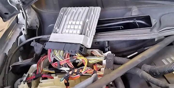
Each module in this system has its own specific purpose. For example, an ECM (Engine Control Module) collects data from numerous temperature and pressure sensors to monitor engine performance.
This data is then used to determine a motor’s fuel adjustments and throttle body positioning (on drive-by-wire systems). Additional modules found on most vehicles include a TCM (Transmission Control Module) and a BCM (Body Control Module), among others.
2005 Nissan Altima (affected by Nissan service bulletin regarding U1000 code)
These modules must communicate with each other to function as intended. For example, a vehicle’s TCM depends on information from the ECM to control shift timing.
Similarly, a vehicle’s BCM is responsible for illuminating certain instrument cluster warning lights when prompted to do so by additional modules.
This communication interface, as a whole, is known as a vehicle’s CAN-bus system. Data is transmitted point-to-point within this system via a series of complex electrical connections.
In some of today’s most advanced systems, this data is relayed in various forms, including 12-volt power, 5-volt references, system grounds, and hertz (Hz) signals.
The U1000 diagnostic trouble code indicates a fault within this communication network, likely negatively impacting data transmission. This communication failure can result from faulty wiring or originate from a module itself.
See also: U0001 Code, U0073 Code, U0100 Code, U0101 Code
Symptoms of the U1000 Code
Depending on the root cause of the U1000 DTC, additional symptoms may or may not be present. In a number of cases, the only indicator of such a problem will be the presence of the underlying code. However, in other cases, concerning drivability-related issues may be encountered.
Additionally, a secondary code is usually stored alongside the U1000 DTC, which serves to identify the affected module or circuit. While this secondary code is used to identify the issue in question, the U1000 DTC serves more to generalize that something is wrong.
Here are some of the most common symptoms associated with the U1000 DTC, many of which have been documented in Nissan service bulletins on this subject.
Hesitation
Engine Stalling
Lack of Power
Failure to Start
Causes of the U1000 Code
The root cause of the U1000 DTC often varies significantly from one vehicle make and model to another. However, most problems of this nature are related to inefficiencies within one or more of a vehicle’s data communication networks.
All secondary codes stored in addition to the U1000 code will further guide you toward identifying the issue at hand. In cases where no other active codes are present, the U1000 code often serves as an electrical anomaly that will not present any other problems.
In some cases, replacing the ECM may be necessary as an appropriate means of rectifying the U1000 code, if a fault in this module has been identified. Other potential causes of the U1000 DTC include damaged wiring, faulty grounds, corroded wiring, and poor connector contact at a wiring harness/module junction.
Is the U1000 Code Serious?
The severity of the U1000 code largely depends on a particular manufacturer’s use of this specific DTC. While Nissan explicitly mentions that the U1000 DTC can lead to a multitude of additional symptoms, many of which can negatively impact a vehicle’s drivability, other manufacturers consider this DTC to be of a much less urgent nature.
In any case, additional diagnostics should be performed on any vehicle displaying a U1000 trouble code at the first available opportunity. Since this code implies that a vehicle’s communication network is operating at less than peak efficiency, the risk of additional problems always exists.
Therefore, a code of this nature, if largely ignored, can pose potential problems, or even leave you stranded, in the near future.
How to Fix
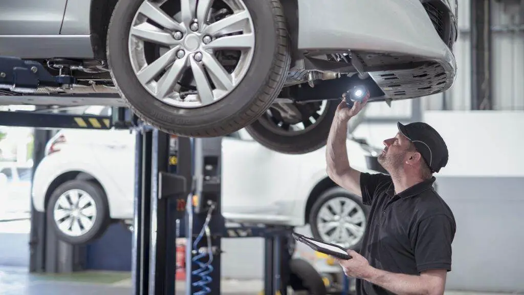
It is best to entrust the repair of the U1000 DTC to your local automotive professional whenever possible. This is because complex testing is often necessary to condemn a faulty module, whichever it may be.
Failing to thoroughly diagnose the issue in question can also lead to significant unnecessary expenses. Furthermore, replacing a module, such as the ECM, typically requires “flashing” it with manufacturer-specific software.
However, motorists can determine the root cause of these issues by following the steps below.
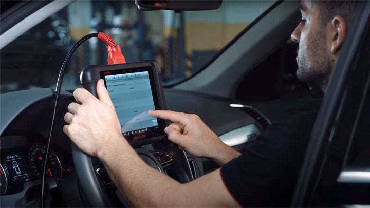
#1 – Look for Additional Codes
Since the U1000 DTC is usually set in addition to secondary codes, all active trouble codes should be recorded for further troubleshooting using an automotive scan tool. In many cases, further diagnosis of these secondary codes will reveal the root causes of your vehicle’s U1000 trouble code.
#2 – Consult Relevant Service Bulletins
Several manufacturers, such as Nissan, have released service bulletins detailing issues related to the U1000 DTC. Reading these service bulletins in their entirety often outlines the upcoming diagnostic process.
#3 – Consult Factory Wiring Diagrams
It is also important to locate a wiring diagram specific to your vehicle’s model. Diagrams of this nature will highlight relevant connections that might prove worthy of further inspection.
#4 – Clean Grounds/Check Connections
Thoroughly clean and inspect all ground connections related to your vehicle’s CAN bus system. Additionally, it is also important to check all wiring harness/module connections for any signs of corrosion.
#5 – Locate Vehicle-Specific Service Documentation
If the U1000 code persists, the appropriate service documentation for your vehicle should be located.
Code U1116 – Invalid or Missing Data for Electric Power Management
What are the possible causes of DTC U1116?
NOTE: The causes listed may not be a complete list of all potential issues, and there could be other causes.
Faulty module that is not communicating
The module’s wiring harness is open or short-circuited
Poor electrical connection in the module’s circuit
How to fix DTC U1116?
Review the “Possible Causes” mentioned above and visually inspect the corresponding wiring harness and connectors. Be sure to check for any damaged components and inspect the connector pins for signs of breakage, bending, dislodgement, or corrosion.
What are the possible symptoms of code U1116?
Check engine light on (or engine maintenance warning light soon)
Code U1116 Description
Modules connected to the serial data circuit monitor for class 2 serial data communications during normal vehicle operation. Operating information and commands are exchanged between modules. When a module receives a message for a critical operating parameter, it records the identification number of the module that sent the message for health monitoring. A critical operating parameter is one that, if not received, requires the module to use a default value for that parameter. When a module does not associate an identification number with at least one critical parameter within 5 seconds of the start of serial data communication, the diagnostic trouble code (DTC) is set.
P3000 – Battery Control System Malfunction
P3000 Possible Causes
HV control system
Lack of fuel
HV battery pack
How to Fix P3000 Code
Check the “Possible causes” listed above. Visually inspect the related cable harness and connectors. Check for damaged components and look for broken, bent, pushed out, or corroded connector pins.
Possible Symptoms
Engine light on (or service engine soon warning light)
P3000 Meaning
Based on the malfunction signal received from the battery electronic control unit (ECU), the system alerts the driver and performs a safety control. This DTC is set when the HV battery state of charge (SOC) decreases due to leaving the vehicle in N position, running out of fuel, or a malfunction in the HV control system.
P3100
Manufacturer-controlled DTC
P3300
Manufacturer-controlled DTC
P3400 – Cylinder deactivation system, bank 1
How severe is this DTC?
Besides the fact that cylinder deactivation issues can reduce fuel efficiency, possible causes can lead to catastrophic engine failure. P3400 should be rectified as soon as possible and classified as severe.
What are some of the symptoms of the code?
Symptoms of a P3400 trouble code may include:
Reduced fuel efficiency
Reduced engine performance
Other cylinder deactivation codes
Engine misfire codes
What are some common causes of the code?
Causes of this code may include:
Low engine oil level or pressure
Faulty variable valve timing control solenoid(s)
Open or shorted cylinder deactivation circuit(s)
PCM programming error or faulty PCM
What are the troubleshooting steps for P3400?
Note: There are known Technical Service Bulletins (TSBs) for certain Honda and Acura vehicles related to this code. These include Honda TSB 11-033, Honda TSB 13-031, and Honda TSB 13-055.
Components essential to the operation of the cylinder deactivation system frequently require engine oil pressure assistance. For this reason, diagnosing cylinder deactivation codes should begin by ensuring the engine is filled to the appropriate level with the correct oil and that engine oil pressure meets specifications. If actual engine oil pressure is in doubt, a manual oil pressure test is necessary.
To achieve an accurate diagnosis of a P3400 code, a diagnostic scanner, a digital volt/ohmmeter (DVOM), and a vehicle information source will be required. If engine oil pressure is in question, a manual pressure gauge will also be needed.
A reliable vehicle information source can produce applicable Technical Service Bulletins (TSBs) that could assist in your diagnosis. It should also provide diagnostic flowcharts, wiring diagrams, connector face views, connector pinout diagrams, and component testing procedures/specifications. You will need this information to reach a correct diagnosis.
Always disconnect controllers before testing system circuits with the DVOM. Failure to do so may damage the controller.
Once you have verified that engine oil pressure meets specifications and performed a visual inspection of associated connectors and wiring, connect the scanner to the vehicle’s diagnostic port. Retrieve all stored codes and associated freeze frame data. Writing down this information (for later reference) may prove useful. Clear the codes and test-drive the vehicle until the PCM enters readiness mode or the code resets.
If the PCM enters readiness mode, you can assume you are dealing with an intermittent code. The conditions that caused it may need to worsen before you can achieve a successful diagnosis. If the code resets, look up the appropriate diagnostic flowchart in the vehicle information source and follow it to conclusion.
Use the DVOM to test the various variable valve timing solenoids. Solenoids that do not meet manufacturer specifications should be considered faulty.
Low engine oil level is the primary contributor to cylinder deactivation system codes
P3404 Cylinder 1 Deactivation Control Circuit / Intake Valve High
How severe is this DTC?
The severity of this code can vary significantly from moderate to severe depending on the specific symptoms of the malfunction. A misfire requires immediate attention as it can cause permanent damage to internal engine components.
What are some of the symptoms of the code?
Symptoms of a P3404 trouble code may include:
Engine may misfire
Increased fuel consumption
Poor engine performance
Service engine soon light
Check engine light illuminated
What are some common causes of the code?
Causes
of this P3404 code may include:
Faulty cylinder deactivation solenoid
Low engine oil level or pressure
Restricted oil passage
Faulty or damaged wiring
Corroded, damaged, or loose connector
Faulty ECM
What are the troubleshooting steps for P3404?
The first step in the troubleshooting process for any malfunction is to research Technical Service Bulletins (TSBs) for the specific vehicle by year, model, and engine. In some circumstances, this can save you considerable time in the long run by pointing you in the right direction.
The second step is to check the condition of the engine oil and confirm it is maintained at the appropriate level. Then locate all components associated with the cylinder 1 deactivation intake valve control circuit and look for obvious physical damage. Based on the specific vehicle, this circuit may incorporate multiple components, including the deactivation solenoid, switches, fault indicators, and the ECM. Perform a thorough visual inspection to verify that the associated wiring shows no obvious defects such as scraping, rubbing, bare wires, or burns. Next, check connectors and connections for security, corrosion, and damaged pins. This process should include all wiring connectors and connections to all components, including the ECM. Consult vehicle-specific technical data to verify the configuration of the cylinder 1 deactivation/intake valve control circuit and confirm each component incorporated into the circuit that may include a fuse or fusible link.
Advanced Steps
Advanced steps become very vehicle-specific and require appropriate advanced equipment to perform accurately. These procedures require a digital multimeter and vehicle-specific technical references.
Voltage Checks
Reference voltage and acceptable ranges may vary depending on the specific vehicle and circuit configuration. Specific technical data will include troubleshooting charts and the proper sequence to follow to help you establish an accurate diagnosis.
If this process identifies the absence of a power source or ground, continuity tests may be required to verify the integrity of wiring, connectors, and other components. Continuity tests should always be performed with power disconnected from the circuit, and normal readings for wiring and connections should be 0 ohms of resistance. Resistance or lack of continuity is an indication of faulty wiring that is open, shorted, or corroded and should be repaired or replaced.
What are the common repairs for this code?
Replacement of the deactivation solenoid
Cleaning corrosion from connectors
Repairing or replacing faulty wiring
Changing oil and filter
Cleaning blocked oil passages
ECM replacement
Common Mistake
Replacing the deactivation solenoid when insufficient oil pressure or faulty wiring causes the ECM to set this code.
I hope the information in this article has been helpful in pointing you in the right direction to correct the issue with the cylinder 1 deactivation/intake valve control circuit fault code. This article is strictly informational, and technical data and service bulletins specific to your vehicle should always take priority.