P052E Positive Performance of Crankcase Ventilation Regulator Valve

What does it mean?

This generic powertrain diagnostic trouble code (DTC) generally applies to many OBD-II vehicles. This may include, but is not limited to, vehicles from Ford, Dodge, Ram, Volvo, etc.

If a P052E code is stored in your OBD-II vehicle, it means that the Powertrain Control Module (PCM) has detected a signal from the crankcase pressure sensor indicating that an inappropriate pressure level exists.

The density (pressure) of the air in the engine crankcase is monitored by the PCM using a voltage input signal from the crankcase pressure sensor. The crankcase pressure sensor input voltage is received (by the PCM) as actual pressure units. Kilopascal (kPa) units or inches of mercury (Hg) are used to measure crankcase pressure. The crankcase pressure sensor is typically located in or near one of the valve covers.

Because the lower end of the internal combustion engine must be sealed to prevent oil leaks, a certain amount of pressure is created there. This pressure is caused by drastic temperature changes, vapors created by the engine oil, and the rapid centrifugal movement of the crankshaft, connecting rods, etc.

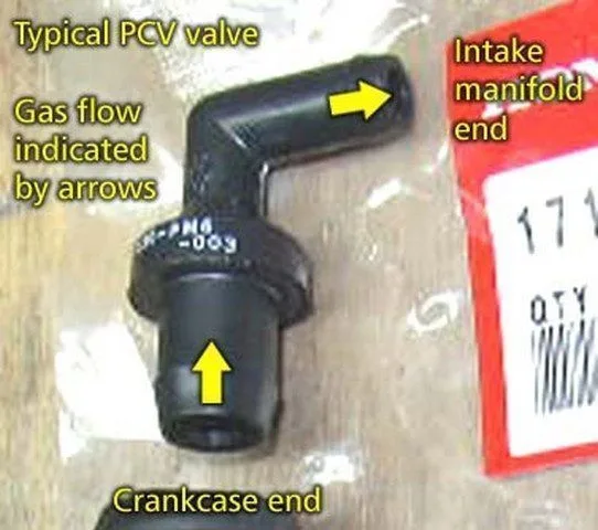
The Positive Crankcase Ventilation (PCV) system uses a carefully controlled intake vacuum to draw pressure from the crankcase through a specially designed valve (PCV valve) that only allows one direction of flow. In the vast majority of vehicle applications, the PCV valve uses direct vacuum from the intake manifold. In this particular application, the PCV vacuum is regulated using an electronically controlled PCV regulation valve. The PCM uses an input signal from the crankcase pressure sensor to determine the vacuum pressure to apply to the PCV for optimal performance. A constant supply of battery voltage is typically applied to one terminal of the PCV regulation valve, and the PCM provides a ground as needed to complete the circuit, position the regulation valve in its housing, and achieve the desired PCV vacuum level.

If the PCM detects that the desired level of crankcase pressure cannot be achieved with the PCV regulation valve, a P052E code will be stored and a Malfunction Indicator Lamp (MIL) may be illuminated.

Photo of a PCV valve, a component of the system:

How severe is this DTC?

Incorrect crankcase pressure can lead to engine oil leaks. A P052E code should be classified as severe and treated accordingly.
What are some of the symptoms of the code?

Symptoms of a P052E engine code may include:

Engine oil leaks
Smoke (vapor) from the area under the hood
Hissing (suction) noise from the engine area
Driving issues caused by a vacuum leak

What are some of the common causes of the code?

Causes

of this code may include:

Faulty PCV regulation valve
Defective PCV valve
Faulty crankcase pressure sensor
Open or shorted wiring of the PCV regulation valve / crankcase pressure sensor
PCM malfunction or PCM programming error

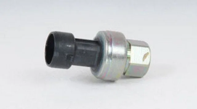
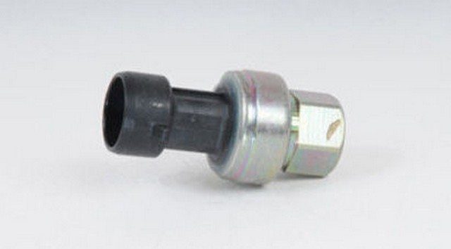
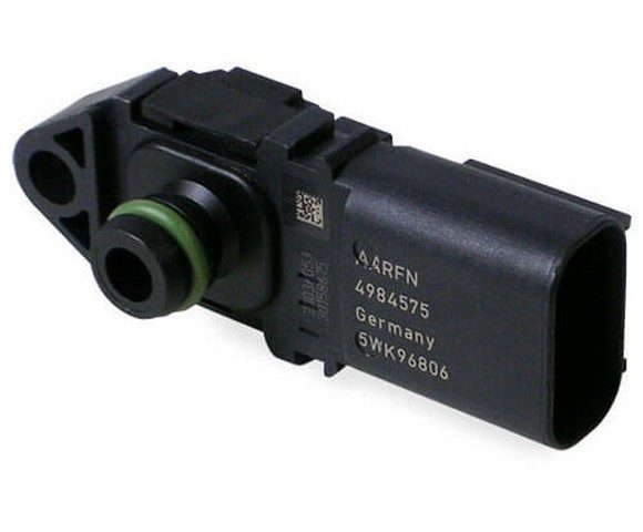
Example of a crankcase pressure sensor:

What are the troubleshooting steps for P052E?

Based on my experience, a manual vacuum gauge, a diagnostic scanner, a digital volt/ohmmeter (DVOM), and a reliable source of vehicle information will be needed when diagnosing a P052E code.

A manual vacuum pressure test should be performed before diagnosing any insufficient crankcase pressure / PCV related codes. If the engine fails to produce sufficient vacuum, it must be repaired before proceeding with your diagnosis. To perform a manual vacuum pressure test, disconnect the PCV vacuum hose and attach your vacuum gauge to it. Your vehicle information resource should provide specifications regarding minimum engine vacuum.

Check all PCV hoses for signs of cracking or breakage and perform necessary repairs. Cracked or collapsed PCV suction hoses can contribute to the conditions that caused the P052E to be stored.

If the engine is in good operating condition and there is no vacuum leak, continue with a visual inspection of all wiring and connectors for the PCV regulation valve and the crankcase pressure sensor. Perform necessary repairs.
Next, I would connect the scanner to the vehicle’s diagnostic port and retrieve all stored codes and freeze frame data. Writing down this information can help you as your diagnosis progresses. After that, clear the codes and test drive the vehicle to see if the code resets.

Use your vehicle information resource to obtain connector face views, wiring diagrams, connector pinout charts, component testing procedures, and specifications. All of this information will be needed to proceed with your diagnosis.

Testing the PCV Regulation Valve and Circuits (KOEO)

Use the scanner to manually activate the PCV regulation valve
Probe the PCV regulation valve power supply circuit with the DVOM’s positive test lead
Use the negative test lead to test the ground of the PCV regulation valve
If there is battery voltage at the PCV regulation valve connector, suspect the valve is faulty
You can test the valve using the DVOM
If it does not meet the recommended specifications, it is certainly not good
If there is no voltage at the PCV regulation valve connector, proceed to the next step

Testing a PCV Regulation Valve Voltage Output Circuit at the PCM Connector

Use the DVOM’s positive test lead to probe the PCV regulation valve output voltage at the PCM connector
The negative test lead should be connected to a known good ground
If there is an output voltage signal at the PCM connector, which is not present at the regulation valve connector, you have an open circuit between the two
If no PCV regulation valve output signal is present at the PCM connector, proceed to the next step

Test the crankcase pressure sensor using the DVOM

With the key on and engine off (KOEO), set the DVOM to the ohms setting and follow the manufacturer’s procedures/specifications for testing the engine crankcase pressure sensor with the connector unplugged
If the sensor in question does not meet the manufacturer’s specifications, it should be considered defective
If the sensor meets the manufacturer’s specifications, proceed to the next step

Use the DVOM to test the reference voltage (usually 5 volts) and a ground at the crankcase pressure sensor connector

With KOEO and the crankcase pressure sensor disconnected, probe the sensor connector’s reference voltage pin with the DVOM’s positive test lead
Connect the negative test lead to the connector’s ground pin to test the entire circuit
If no reference voltage is detected at the sensor connector, locate the PCM and test the corresponding circuit at the PCM connector. Use the DVOM’s positive test lead
The negative test lead should be connected to a known good ground for this test
If there is no reference voltage at the PCM connector, suspect a PCM failure or programming error
If there is no ground at the sensor connector, use your vehicle information source to locate the ground source and ensure it is securely attached to the engine block or battery
If there is reference voltage and ground at the crankcase pressure sensor connector, proceed to the next step

Test the crankcase pressure sensor signal circuit voltage using the DVOM

With the key on engine running (KOER) and the engine crankcase pressure sensor reconnected, use the DVOM’s positive lead to probe the sensor’s signal voltage just behind the connector
The negative test lead should again be connected to a battery ground
Use the vacuum gauge to obtain the correct crankcase pressure and compare the sensor’s signal voltage to the pressure-voltage chart in your vehicle information resource
If the crankcase pressure sensor signal voltage is incorrect, consider the sensor faulty
If the crankcase pressure sensor signal voltage (at the sensor connector) reflects the correct voltage level, proceed to the next step

Test the crankcase pressure sensor signal circuit at the PCM connector

With KOER, use the DVOM positive test lead to probe the crankcase pressure sensor signal circuit at the PCM connector
The negative test lead should be connected to a battery ground
If a correct crankcase pressure sensor signal is found at the sensor connector but not at the corresponding circuit of the PCM connector, suspect an open circuit between the two

If the PCV regulation valve / crankcase pressure sensor and all circuits meet specifications, suspect a PCM failure or PCM programming error.

Technical Service Bulletins (TSBs) that parallel the vehicle in question (as well as the symptoms and stored codes) can assist in your diagnosis

P052F ISO/SAE reserved

P00C0 – P00FF ISO/SAE Reserved

P0530 A/C Refrigerant Pressure Sensor Circuit Malfunction

Explanation of Code P0530: “A/C Refrigerant Pressure Sensor Circuit Malfunction”


Definition

Code P0530 indicates a problem in the air conditioning (A/C) refrigerant pressure sensor circuit. This sensor transmits the system pressure to the control module (BCM, ECC, or ECM) to regulate the A/C compressor and maintain stable cabin temperatures.


Severity

  • Level: 🟠 Moderate (the A/C system may not work, but the vehicle remains drivable).
  • Urgency:
  • Risk of refrigerant leak (dangerous for the environment and health).
  • Compressor damage if the system runs dry.

Symptoms

  • 🌡️ Ineffective air conditioning (little or no cold air).
  • 🔄 Erratic temperatures (random hot/cold).
  • ⚠️ A/C compressor not engaging.
  • 💡 Flashing A/C light or illuminated check engine light (MIL).

Main Causes

  1. Faulty A/C pressure sensor:
  • Damaged, corroded sensor, or leak at the connection.
  1. Electrical issue:
  • Cut wires, short circuit, corroded connector.
  1. Incorrect refrigerant level:
  • Leak in the system (level too low) or overcharge.
  1. ECC/BCM module failure:
  • Software error or failure of the climate control module.

Diagnostic Procedure

Step 1: Check Technical Service Bulletins (TSB)

  • Consult TSBs for your model (e.g., TSB 1234-56 for certain Honda Civics with faulty sensors).

Step 2: Read Live Data

  • Use an OBD2 scanner (e.g., Autel MaxiCOM) to monitor:
  • A/C pressure (in psi or kPa).
  • Sensor signal (typically 0.5V to 4.5V).
  • Compare with manufacturer specifications.

Step 3: Test the Pressure Sensor

  • Electrical test (3-wire sensor):
  • Wire 1: 5V power (measure with a multimeter).
  • Wire 2: Ground (check continuity).
  • Wire 3: Signal (should vary with pressure).

Step 4: Check Refrigerant Level

  • Professional method: Use A/C gauges to measure pressure (⚠️ Do not handle refrigerant without proper equipment!).
  • Typical values:
  • Low pressure: 25-35 psi.
  • High pressure: 150-250 psi.

Step 5: Inspect Wiring

  • Check sensor wires for:
  • Cuts, chafing (e.g., near moving parts).
  • Corrosion (clean with contact spray).

Solutions & Costs

Problem Solution Average Cost
Faulty A/C sensor Replace sensor €30 – €150
Refrigerant leak Repair leak + recharge €100 – €400
Damaged wiring Repair or replace harness €50 – €200
BCM/ECC reprogramming Software update €80 – €250

Mistakes to Avoid

  • Recharging refrigerant without checking for leaks: Risk of overpressure and compressor damage.
  • Ignoring related codes (e.g., P0531, P0532): They may indicate a common cause.

Practical Case

  • Problem: Code P0530 on a Renault Clio IV with ineffective A/C.
  • Diagnosis: Corroded A/C pressure sensor (leak at the connector).
  • Solution: Sensor replacement (€45) + connector cleaning.

Pro Tips

  • Use a UV dye kit to detect refrigerant leaks.
  • If the compressor doesn’t engage, test its relay before condemning the sensor.

Safety Warning

  • ⚠️ Refrigerant is hazardous: Wear goggles and gloves. Consult a professional if you are not trained.
  • ⚠️ Do not disassemble the A/C system without a refrigerant recovery tool.

Quick Summary

  1. Check TSBs and read OBD2 data.
  2. Test the sensor and wiring.
  3. Check refrigerant level with gauges.
  4. Replace the sensor or repair the leak if necessary.

If the problem persists, consult a certified A/C specialist to avoid refrigerant-related risks! 🔧❄️

P0531 A/C Refrigerant Pressure Sensor Circuit Range / Performance

What does it mean?

This is a generic diagnostic trouble code (DTC) and generally applies to OBD-II vehicles. Vehicle makes may include, but are not limited to, Chevrolet/Chevy, Ford, Volvo, Dodge, Hyundai, Vauxhall, Honda, Nissan, Renault, Alfa Romeo, etc.

The A/C refrigerant pressure sensor helps the HVAC (Heating, Ventilation, and Air Conditioning) system regulate the temperature inside the vehicle according to your requirements.

The BCM (Body Control Module) or ECC (Electronic Climate Control) monitors the sensor to determine system pressures, which in turn can engage/disengage the compressor accordingly.

The A/C refrigerant pressure sensor is a pressure transducer; it converts the refrigerant system pressure into an analog electrical signal to allow monitoring by the vehicle’s modules. Typically, it does this using 3 wires: a 5-volt reference wire, a signal wire, and a ground wire. The modules compare the signal wire values to the 5-volt reference and can instantly calculate system pressures with this information.

The ECM (Engine Control Module) illuminates the MIL (Malfunction Indicator Lamp) with P0531 and related codes (P0530, P0531, P0532, and P0533) when it detects a fault in the A/C refrigerant pressure sensor or its circuits. Before performing any type of diagnosis and/or repair on the air conditioning system, you must ensure you are aware of the many risks associated with working with pressurized refrigerant. Most of the time, you can diagnose this type of code without opening the refrigeration system.

Code P0531 A/C Refrigerant Pressure Sensor Circuit Range/Performance is set when one of the modules monitors the A/C refrigerant pressure sensor abnormally, particularly an out-of-range condition. An example of an A/C refrigerant pressure sensor:

How severe is this DTC?

In my opinion, the severity of any code related to HVAC will be fairly low. In this case, pressurized refrigerant is involved, so it might be more of an urgent issue. Who knows, a refrigerant leak could be causing this code, and a refrigerant leak is certainly a hazard, so make sure you have some basic refrigerant safety knowledge before attempting any type of repair on the air conditioning system.
What are some of the symptoms of the code?

Symptoms of a P0531 diagnostic code may include:

Inaccurate temperatures from the fan air
Limited HVAC operation
Erratic/fluctuating fan air temperature
A/C compressor not engaging when needed
HVAC system operating abnormally

What are some common causes of the code?

Causes

of this P0531 code may include:

Faulty or damaged A/C refrigerant pressure sensor
Leak from the A/C refrigerant pressure sensor
Low or incorrect refrigerant pressures/level
Damaged wire(s) (open, short to +, short to -, etc.)
Damaged connector
ECC (Electronic Climate Control) or BCM (Body Control Module) issue
Poor connections

What are the diagnostic and troubleshooting steps for P0531?

Before starting the troubleshooting process for any malfunction, you should look up Technical Service Bulletins (TSBs) for the specific vehicle by year, model, and transmission. This step can save you time and money during diagnosis and repair!
Basic Step #1

Depending on the tools/knowledge you have access to, you can easily check the operation of the A/C refrigerant pressure sensors. The two simple ways to do this are: 1. Depending on the capabilities and limitations of your OBD reader/scan tool, you may be able to monitor refrigerant pressures and other desired values while the system is running to check sensor functionality. 2. If you have a set of A/C manifold gauges, you can monitor pressures mechanically and compare them to the specific desired values from your manufacturer.

TIP: If you have no experience with refrigerant, I would not recommend diving into pressure testing, so make sure you are not in over your head here; refrigerant is an environmental hazard, so it’s not something to play with.
Basic Step #2

Test the A/C refrigerant pressure sensor. As I mentioned earlier, most of the time, this sensor is a 3-wire pressure transducer. That said, testing it will involve testing between the pins and recording your results. The desired values for this test vary significantly between manufacturers, temperatures, sensor type, etc., so make sure your information is accurate.

NOTE: Ensure you are using the appropriate test pins with your multimeter when testing pins/connectors. A damaged pin or connector could cause future intermittent electrical gremlins that are hard to find.
Basic Step #3

Check the wiring. Sometimes these sensors will be mounted on an A/C pressure line or near a line connection, so the harness will be routed accordingly. I have personally seen these sensors damaged by moving parts under the hood because the line was not properly secured. Make sure the sensor is in good physical condition and the line is properly attached.

P0532 A/C Refrigerant Pressure Sensor, Low Circuit

What does it mean?

This is a generic diagnostic trouble code (DTC) and generally applies to OBD-II vehicles. Vehicle makes may include, but are not limited to, Chevrolet/Chevy, Ford, Volvo, Dodge, Hyundai, Vauxhall, Honda, Nissan, Renault, Alfa Romeo, etc.

The A/C refrigerant pressure sensor helps the HVAC (Heating, Ventilation, and Air Conditioning) system regulate the temperature inside the vehicle according to your requirements.

The BCM (Body Control Module) or ECC (Electronic Climate Control) monitors the sensor to determine system pressures, which in turn can engage/disengage the compressor accordingly.

The A/C refrigerant pressure sensor is a pressure transducer; it converts the refrigerant system pressure into an analog electrical signal to allow monitoring by the vehicle’s modules. Typically, it does this using 3 wires: a 5-volt reference wire, a signal wire, and a ground wire. The modules compare the signal wire values to the 5-volt reference and can instantly calculate system pressures with this information.

The ECM (Engine Control Module) illuminates the MIL (Malfunction Indicator Lamp) with P0532 and related codes (P0530, P0531, P0532, and P0533) when it detects a fault in the A/C refrigerant pressure sensor or its circuits. Before performing any type of diagnosis and/or repair on the air conditioning system, you must ensure you are aware of the many risks associated with working with pressurized refrigerant. Most of the time, you can diagnose this type of code without opening the refrigeration system.

The P0532 A/C Refrigerant Pressure Sensor Circuit Low code is set when one of the modules detects a low electrical value in the A/C refrigerant pressure sensor or its circuit. An example of an A/C refrigerant pressure sensor:

How severe is this DTC?

In my opinion, the severity of any HVAC-related code will be fairly low. In this case, pressurized refrigerant is involved, so it might be more of an urgent issue. Who knows, a refrigerant leak could be causing this code, and a refrigerant leak is certainly a hazard, so make sure you have some basic refrigerant safety knowledge before attempting any kind of repair on the air conditioning system.
What are some of the symptoms of the code?

Symptoms of a P0532 diagnostic trouble code may include:

Inaccurate temperatures from the fan air
Limited HVAC use
Erratic/fluctuating fan air temperature
A/C compressor not engaging when needed
HVAC system operating abnormally

What are some common causes of the code?

Causes

of this P0532 code may include:

Faulty or damaged A/C refrigerant pressure sensor
A/C refrigerant pressure sensor leak
Low or incorrect refrigerant pressures/level
Damaged wire(s) (open, short to +, short to -, etc.)
Damaged connector
ECC (Electronic Climate Control) or BCM (Body Control Module) issue
Poor connections

What are the diagnostic and troubleshooting steps for P0532?

Before starting the troubleshooting process for any malfunction, you should look up Technical Service Bulletins (TSBs) for the specific vehicle by year, model, and transmission. This step can save you time and money during diagnosis and repair!
Basic Step #1

Depending on the tools/knowledge you have access to, you can easily check the operation of the A/C refrigerant pressure sensors. The two simple ways to do this are: 1. Depending on the capabilities and limitations of your OBD reader/scan tool, you may be able to monitor refrigerant pressures and other desired values while the system is running to check sensor functionality. 2. If you have a set of A/C manifold gauges, you can monitor pressures mechanically and compare them with the specific desired values from your manufacturer.

TIP: If you have no experience with refrigerant, I would not recommend diving into pressure testing, so make sure you are not in over your head here; refrigerant is an environmental hazard, so it’s not something to play with.
Basic Step #2

Test the A/C refrigerant pressure sensor. As I mentioned earlier, most of the time, this sensor is a 3-wire pressure transducer. That said, testing it will involve testing between the pins and recording your results. The desired values for this test vary widely between manufacturers, temperatures, sensor type, etc., so make sure your information is accurate.

NOTE: Ensure you are using the appropriate test pins with your multimeter when testing pins/connectors. A damaged pin or connector could cause future intermittent electrical gremlins that are hard to find.
Basic Step #3

Check the wiring. Sometimes these sensors will be mounted on an A/C pressure line or near a line connection, so the harness will be routed accordingly. I have personally seen these sensors damaged by moving parts under the hood because the line was not properly secured. Make sure the sensor is in good physical condition and the line is properly attached.

P0533 A/C Refrigerant Pressure Sensor Circuit High

What Does It Mean?

This is a generic diagnostic trouble code (DTC) and generally applies to OBD-II vehicles. Vehicle brands may include, but are not limited to, Chevrolet/Chevy, Ford, Volvo, Dodge, Hyundai, Vauxhall, Honda, Nissan, Renault, Alfa Romeo, etc.

A/C Refrigerant Pressure Sensor

The A/C refrigerant pressure sensor helps the HVAC (heating, ventilation, and air conditioning) system regulate the temperature inside the vehicle according to your requirements.

  • Operation:
    The sensor converts the refrigerant system pressure into an analog electrical signal through its 3 wires: a 5-volt reference wire, a signal wire, and a ground wire. Vehicle modules compare the signal wire values to the reference to calculate the pressure.
  • Involved Modules:
    The BCM (Body Control Module) or ECC (Electronic Climate Control) monitors this sensor to determine system pressures and engage/disengage the compressor as needed.

Code Signaling

The ECM (engine control module) activates the MIL (malfunction indicator lamp) by displaying code P0533 along with related codes (P0530, P0531, P0532, and P0533) when a fault is detected in the A/C refrigerant pressure sensor or its circuits.


Severity of the DTC

In my opinion, the severity of any code related to the HVAC (heating, ventilation, and air conditioning) system is often low. However, in this case, pressurized refrigerant is involved, which could indicate an urgent issue. A refrigerant leak, for example, poses a real danger. Make sure you have basic refrigerant safety knowledge before working on the system.


Symptoms of Code P0533

Symptoms that may accompany this code include:

  • Inaccurate temperatures from the fan air
  • Limited use of the HVAC system
  • Erratic or fluctuating fan air temperature
  • The A/C compressor not engaging when needed
  • Abnormal HVAC system operation
  • Additional Points:
    • Increased fuel consumption due to inefficient A/C operation
    • Unusual noises from the compressor or refrigerant lines

Common Causes of the Code

The most frequent causes of this P0533 code may be:

  • Faulty or damaged A/C refrigerant pressure sensor
  • Leak in the A/C refrigerant pressure sensor or circuit
  • Low or incorrect refrigerant pressures or levels
  • Damaged, open, or shorted wires (short to + or short to -)
  • Damaged connector
  • Issue with the ECC (Electronic Climate Control) or BCM (Body Control Module)
  • Poor connections or grounding problems
  • Software error in the control module

Diagnosis and Troubleshooting of P0533

Before any intervention, consult the technical service bulletins (TSBs) specific to the vehicle’s year, model, and transmission. This step can save you time and money.

Basic Step #1: Sensor Check

Depending on your tools and skills, you can check the operation of the A/C refrigerant pressure sensor in two ways:

a) Using an OBD Reader/Scan Tool

  • Monitor refrigerant pressures and other values while the system is running to validate the sensor’s proper operation.

b) Using A/C Manifold Gauges

  • Compare mechanically measured pressures to the manufacturer’s recommended reference values.

Tip: If you have no experience with refrigerant, avoid performing pressure tests yourself. Refrigerant poses an environmental hazard and can be risky.

Basic Step #2: Testing the Sensor

  • Perform tests between the sensor pins to record values.
  • Ensure your reference information (from the manufacturer) is accurate, as it may vary by model, temperature, and sensor type.

Basic Step #3: Wiring Check

  • Inspect the sensor’s wiring and connections.
  • Sometimes, the sensor is mounted on an A/C pressure line and may suffer mechanical damage (e.g., from moving parts under the hood).
  • Ensure the sensor and line are in good condition and securely fastened.

In conclusion, even though code P0533 is not always critical, it can reveal a more significant malfunction in the air conditioning system. Regular inspection and proper maintenance of the system can prevent such error codes from occurring.

P0534 Air Conditioning Refrigerant Charge Loss

What does it mean?

This is a generic diagnostic trouble code (DTC) and generally applies to OBD-II vehicles. Vehicle makes may include, but are not limited to, Chevrolet/Chevy, Land Rover, GM, etc.

When a P0534 code is stored, it means the Powertrain Control Module (PCM) has detected a low freon condition in the air conditioning (A/C) system.

The automotive A/C system is lubricated with a mixture of specially designed oil and freon. Even if the proper amount of appropriate oil was present in the A/C system, without the freon, it could not circulate to vital areas. Without this mixture, the compressor would suffer catastrophic failure and the condenser would be filled with a form of gummy metallic debris.
To protect the compressor and other expensive A/C components, pressure sensors are positioned in certain areas of the system.

A high-pressure cut-off switch at the rear of the compressor (or in a discharge line) can protect the A/C system from an extreme overpressure condition. This type of condition would likely be caused by a lack of airflow through the condenser or engine overheating.

To protect the A/C system from a low freon condition, a low-pressure cut-off switch is positioned on the suction side of the system near the accumulator or orifice tube (depending on A/C system configuration).

The A/C low-pressure cut-off switch is made with a pressure-sensitive contact that closes when A/C pressure exceeds the target level (usually above 30 psi). It is typically screwed onto a Schrader valve on the A/C system suction line or accumulator. As long as A/C system pressure remains within programmed specifications, the contact in the low-pressure switch remains closed and the A/C compressor clutch power circuit is completed as desired. When A/C system pressure falls below the minimum threshold, the contact in the low-pressure switch opens and voltage to the compressor clutch is interrupted.

The A/C low-pressure cut-off switch also provides the PCM with an on/off signal. If the PCM detects a signal from the low-pressure cut-off switch indicating a low freon condition, a P0534 code will be stored and a Malfunction Indicator Lamp (MIL) may be illuminated. In most cases, multiple failures will be required for the code to be stored and for the MIL to illuminate.

A refrigerant pressure sensor:

How serious is this DTC?

A stored P0534 code relates exclusively to the air conditioning system and does not affect engine drivability. It should not be classified as serious.
What are some of the symptoms of the code?

Symptoms of a P0534 diagnostic trouble code may include:

Air conditioner will not blow cold air
A/C compressor switch may flash
Compressor clutch may cycle on and off repeatedly
A/C compressor clutch engagement may be disabled

What are some common causes of the code?

Causes

of this P0534 code may include:

Freon leak (low freon) in the A/C system
Faulty low-pressure cut-off switch
Open or shorted circuit or connector in the A/C system

What are the diagnostic and troubleshooting steps for P0534?

When a P0534 code is stored, a general performance check of the A/C system is recommended. Be aware that handling certain types of freon requires federally mandated certification in many areas. Additionally, the A/C system should only be serviced by qualified individuals. High-pressure freon can be dangerous in several ways and the A/C system can be damaged if the correct amount of freon is not used. Before beginning your diagnosis, the A/C system must be filled to the correct level with the appropriate freon and oil (quantity and type). If charge specifications are not visible in the under-hood area, check a reliable source of vehicle information. A set of automotive A/C gauges, a vacuum pump, and some type of oil dispenser will be needed to service the A/C system. If the system has a small leak, an ultraviolet leak detection dye injection is also recommended. This will help diagnose a leak if the freon escapes again.

Once the A/C system has been serviced and is full of freon, it may be necessary to clear the code before the A/C compressor clutch coil can be restored. Connect the scanner to the vehicle’s diagnostic connector and retrieve all stored codes and freeze frame data. Write all of this down before clearing the codes. With the A/C system full of freon, operate it and see if the P0534 resets.

If the code resets, use a digital volt/ohmmeter (DVOM) to check the low-pressure cut-off switch. This can be done by starting the engine and turning the A/C to maximum with the fan on high. Be careful when working around moving parts and connect the DVOM’s negative test lead to a good known ground. Use the positive test lead to probe the wires at the low-pressure switch connector. This will be performed with the low-pressure cut-off switch connector plugged in. All wires (usually three) should have battery voltage.

Here are several possible scenarios:
None of the circuits have voltage

Check system fuses with the DVOM
Check the A/C on/off switch
Check the low-pressure switch connector
Check the A/C compressor relay

One of the circuits has power; the others do not

The low-pressure switch may be faulty
Jump the switch and see if the compressor clutch engages
If the clutch engages with the connector jumped, the low-pressure cut-off switch is bad

Low freon conditions are the primary cause of storing a P0534. Ensure the A/C system is full of freon before diagnosing this code

P0535 Air Conditioning Evaporator Temperature Sensor Circuit

This is a generic diagnostic trouble code (DTC) and applies to OBD-II vehicles. This can include, but is not limited to, vehicles from Ford, Chevrolet, Dodge, Ram, etc. Although generic, the exact repair steps may vary by year, make, model, and powertrain configuration.

Essentially, the air conditioning evaporator works in the opposite way as a condenser. The condenser converts gas into fluid, and the evaporator converts fluid into gas while absorbing heat from the fan air passing through it during the process.

Its purpose is to remove heat from the air inside the passenger compartment, thereby lowering the temperature inside the car. The functionality of the A/C evaporator temperature sensor is crucial for the proper operation of your HVAC (heating, ventilation, and air conditioning) system. The ECM (Engine Control Module) uses the electrical values from this sensor to adjust the interior temperature according to your needs, in coordination with your evaporator among other A/C components.

The ECM triggers P0535 and related codes (P0536, P0537, P0538, and P0539) when it detects a condition outside the desired electrical range in the A/C evaporator temperature sensor or its circuits. This could also be a mechanical or electrical issue. Always keep in mind the sensor’s environment (any sensor, for that matter), as it might be subjected to an environment with unique problems.

P0535 A/C Evaporator Temperature Sensor Circuit Code is set when the ECM detects a general malfunction within the A/C evaporator temperature sensor or its circuits.

Photo of an evaporator temperature sensor style:

How severe is this DTC?

Since your entire HVAC system was designed with the sole purpose of keeping humans more comfortable, the severity here is set at the lowest possible level. A complete HVAC system malfunction would pose virtually no threat to your safety. That being said, if you value comfort like I do, you’ll need to address this issue immediately.
What are some of the symptoms of the code?

Symptoms of a P0535 trouble code may include:

No cold air blown from the vents
Erratic/fluctuating fan air temperature
A/C compressor clutch not engaging
HVAC system not operating as desired

What are some common causes of the code?

Causes

of this P0535 code may include:

Faulty or damaged A/C evaporator core
Faulty A/C evaporator temperature sensor
Faulty ECM (Engine Control Module)
Wiring issue in the sensor circuit
Wiring harness connector problem
Intermittent electrical connection
Internal resistance (corrosion, damaged harness, overheated circuit, etc.)

What are the troubleshooting steps for P0535?

Make sure to check the Technical Service Bulletins (TSBs) for your vehicle. Accessing a known fix can save you time and money during diagnosis.
Basic Step #1

Locate and visually inspect the A/C evaporator temperature sensor. Generally, the evaporator core is located inside the HVAC air box (heating, ventilation, and air conditioning). The A/C evaporator temperature sensor is typically mounted on the evaporator itself or very close to it. You may be able to access it by looking under the dashboard fairly easily. It’s also possible you’ll need to remove many plastic panels and/or the radio, so always refer to your service manual for the specific location. Keep an eye out for any signs of overheating and/or corrosion on the sensor itself. This could indicate your problem. If it proves faulty, replace the sensor.

TIP: Ensure your interior is at a reasonable temperature. Start prying on cold plastic and it will break, so be careful.
Basic Step #2

Test the temperature sensor. Most of the time, these sensors are resistance-type sensors. In other words, the resistance inside the sensor changes in direct relation to the temperature. Understanding how this works probably gives you an idea of how to diagnose the sensor itself. Usually, the manufacturer will have a desired resistance at certain temperatures. Using your multimeter, you can record the resistance in the sensor and compare it to the desired values specified by your manufacturer. If an open circuit is present, you may have internal resistance in the sensor itself and it will need to be replaced.

NOTE: Your manufacturer may have a specific diagnostic strategy depending on the sensor type, make, model, etc., so always refer to your service manual. If you are not comfortable with electrical testing and/or working around refrigeration systems, take your vehicle to a reputable shop.
Basic Step #3

Check the wiring. Given the location of the evaporator temperature sensor, it may be easy to locate and trace the harness to check for any obvious signs of damage. Especially where the driver’s and passengers’ feet might interfere with the wiring (if possible).

P0536 A/C Evaporator Temperature Sensor Range

What does it mean?

This is a generic diagnostic trouble code (DTC) that applies to OBD-II vehicles. This may include, but is not limited to, vehicles from Ford, Chevrolet, Dodge, Ram, etc. Although generic, the exact repair steps may vary depending on the year, make, model, and powertrain configuration.

Essentially, the air conditioning evaporator works in the opposite way as a condenser. The condenser converts gas into fluid, and the evaporator converts fluid into gas while absorbing heat from the fan air passing through it during the process.

Its purpose is to remove heat from the air inside the cabin, thereby reducing the temperature inside the car. The functionality of the A/C evaporator temperature sensor is crucial for the proper operation of your HVAC (heating, ventilation, and air conditioning) system. The ECM (Engine Control Module) uses the electrical values from this sensor to adjust the interior temperature according to your needs, in coordination with your evaporator among other A/C components.

The ECM triggers P0536 and related codes (P0535, P0537, P0538, and P0539) when it detects a condition outside the desired electrical range in the A/C evaporator temperature sensor or its circuits. This could also be a mechanical or electrical issue. Always keep in mind the sensor’s environment (any sensor, for that matter), as it might be subjected to an environment with unique problems.

P0536 A/C Evaporator Temperature Sensor Circuit Range/Performance code is set when the ECM detects a range or performance issue in the A/C evaporator temperature sensor or its circuits.

Photo of an evaporator temperature sensor style:

How severe is this DTC?

Since your entire HVAC system was designed with the sole purpose of keeping humans more comfortable, the severity here is set at the lowest possible level. A complete HVAC system malfunction would pose virtually no threat to your safety. That being said, if you value comfort like I do, you’ll need to address this issue immediately.
What are some of the symptoms of the code?

Symptoms of a P0536 trouble code may include:

No cold air blown from the vents
Erratic/fluctuating fan air temperature
A/C compressor clutch does not engage
HVAC system not operating as desired

What are some common causes of the code?

Causes

of this P0536 code may include:

Faulty or damaged A/C evaporator core
Faulty A/C evaporator temperature sensor
Faulty ECM (Engine Control Module)
Wiring issue in the sensor circuit
Wiring harness connector problem
Intermittent electrical connection
Internal resistance (corrosion, damaged harness, overheated circuit, etc.)

What are the troubleshooting steps for P0536?

Make sure to check the Technical Service Bulletins (TSBs) for your vehicle. Access to a known fix can save you time and money during diagnosis.
Basic Step #1

Locate and visually inspect the A/C evaporator temperature sensor. Generally, the evaporator core is located inside the HVAC air box (heating, ventilation, and air conditioning). The A/C evaporator temperature sensor is usually mounted on the evaporator itself or very close to it. You may be able to access it by looking under the dashboard fairly easily. It’s also possible that you’ll need to remove many plastic panels and/or the radio, so always refer to your service manual for the specific location. Keep an eye out for any signs of overheating and/or corrosion on the sensor itself. This could indicate your problem. If it proves faulty, replace the sensor.

TIP: Make sure your interior is at a reasonable temperature. Start prying on cold plastic and it will break, so be careful.
Basic Step #2

Test the temperature sensor. Most of the time, these sensors are resistance-type sensors. In other words, the resistance inside the sensor changes in direct relation to the temperature. Understanding how this works probably gives you an idea of how to diagnose the sensor itself. Usually, the manufacturer will have a desired resistance at certain temperatures. Using your multimeter, you can record the resistance in the sensor and compare it to the desired values specified by your manufacturer. If an open is present, you may have internal resistance in the sensor itself and it will need to be replaced.

NOTE: Your manufacturer may have a specific diagnostic strategy depending on the sensor type, make, model, etc., so always refer to your service manual. If you are not comfortable with electrical testing and/or working around refrigeration systems, take your vehicle to a reputable shop.
Basic Step #3

Check the wiring. Given the location of the evaporator temperature sensor, it may be easy to locate and trace the harness to check for any obvious signs of damage. Especially where the driver’s and passengers’ feet could interfere with the wiring (if possible).

P0537 Low A/C Evaporator Temperature Sensor Circuit

What Does It Mean?

This is a generic diagnostic trouble code (DTC) that applies to OBD-II vehicles. This may include, but is not limited to, vehicles from Ford, Chevrolet, Dodge, Ram, etc. Although generic, the exact repair steps may vary depending on the year, make, model, and powertrain configuration.

Essentially, the A/C evaporator works in the opposite way as a condenser. The condenser converts gas into fluid, and the evaporator converts fluid into gas while absorbing heat from the fan air passing through it during the process.

Its purpose is to remove heat from the air inside the cabin, thereby reducing the temperature inside the car. The functionality of the A/C evaporator temperature sensor is crucial for the proper operation of your HVAC (Heating, Ventilation, and Air Conditioning) system. The ECM (Engine Control Module) uses the electrical values from this sensor to adjust the interior temperature according to your needs, in coordination with your evaporator among other A/C components.

The ECM triggers P0537 and related codes (P0535, P0536, P0538, and P0539) when it detects a condition outside the desired electrical range in the A/C evaporator temperature sensor or its circuits. This could also be a mechanical or electrical issue. Always keep in mind the sensor’s environment (any sensor, for that matter), as it might be subjected to an environment with unique problems.

P0537 A/C Evaporator Temperature Sensor Circuit Low code is set when the ECM detects an unexpected low electrical condition in the A/C evaporator temperature sensor or its circuits.

Photo of an evaporator temperature sensor style:

How Severe Is This DTC?

Since your entire HVAC system was designed with the sole purpose of keeping humans more comfortable, the severity here is set at the lowest possible level. A complete HVAC system malfunction would pose virtually no threat to your safety. That being said, if you value comfort like I do, you’ll need to address this issue immediately.
What are some of the symptoms of the code?

Symptoms of a P0537 trouble code may include:

No cold air blown from the vents
Erratic/fluctuating fan air temperature
A/C compressor clutch does not engage
HVAC system not operating as desired

What are some common causes of the code?

Causes

of this P0537 code may include:

Faulty or damaged A/C evaporator core
Faulty A/C evaporator temperature sensor
Faulty ECM (Engine Control Module)
Wiring issue in the sensor circuit
Wiring harness connector problem
Intermittent electrical connection
Internal resistance (corrosion, damaged harness, overheated circuit, etc.)

What are the troubleshooting steps for P0537?

Make sure to check the Technical Service Bulletins (TSBs) for your vehicle. Access to a known fix can save you time and money during diagnosis.
Basic Step #1

Locate and visually inspect the A/C evaporator temperature sensor. Generally, the evaporator core is located inside the HVAC air box (Heating, Ventilation, and Air Conditioning). The A/C evaporator temperature sensor is usually mounted on the evaporator itself or very close to it. You may be able to access it by looking under the dashboard fairly easily. It’s also possible that you’ll need to remove many plastic panels and/or the radio, so always refer to your service manual for the specific location. Keep an eye out for any signs of overheating and/or corrosion on the sensor itself. This could indicate your problem. If it proves faulty, replace the sensor.

TIP: Ensure your interior is at a reasonable temperature. Start prying on cold plastic and it will break, so be careful.
Basic Step #2

Test the temperature sensor. Most of the time, these sensors are resistance-type sensors. In other words, the resistance inside the sensor changes in direct relation to the temperature. Understanding how this works probably gives you an idea of how to diagnose the sensor itself. Usually, the manufacturer will have a desired resistance at certain temperatures. Using your multimeter, you can record the resistance in the sensor and compare it to the desired values specified by your manufacturer. If an open is present, you may have internal resistance in the sensor itself and it will need to be replaced.

NOTE: Your manufacturer may have a specific diagnostic strategy depending on the sensor type, make, model, etc., so always refer to your service manual. If you are not comfortable with electrical testing and/or working around refrigeration systems, take your vehicle to a reputable shop.
Basic Step #3

Check the wiring. Given the location of the evaporator temperature sensor, it may be easy to locate and trace the harness to check for any obvious signs of damage. Especially where the driver’s and passengers’ feet might interfere with the wiring (if possible).