Revolutionizing Vehicle Emissions with Biofuel Innovation
Mazda has unveiled a groundbreaking concept that could transform how we view automotive emissions. By integrating algae-based biofuels with a specialized exhaust system, the automaker proposes a solution where gasoline-powered vehicles might achieve carbon-negative status. This approach goes beyond mere emission reduction, actively capturing more carbon dioxide than the vehicle produces during operation.
How the Carbon-Capture System Operates
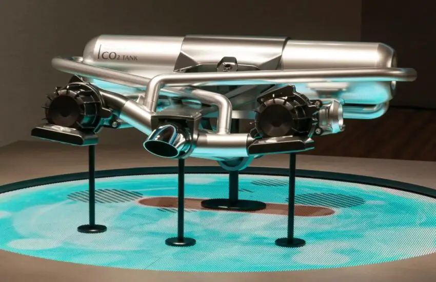
The innovative exhaust system functions as an absorbing layer that traps CO2 as it exits the engine. Unlike conventional exhausts that simply direct gases away from the vehicle, this design incorporates materials capable of sequestering carbon emissions directly at the source. When combined with biofuels derived from algae—which absorb CO2 during their growth phase—the complete fuel cycle could potentially remove more carbon from the atmosphere than it releases.
The Algae Biofuel Advantage
Algae-based biofuels serve as the perfect partner for this carbon-capture technology. These renewable fuels are produced from microorganisms that consume carbon dioxide during photosynthesis. When burned in an engine equipped with Mazda’s capture system, the carbon released represents part of a continuous cycle rather than new atmospheric pollution. This symbiotic relationship between biofuel production and emission capture creates a compelling case for carbon-negative transportation.
Potential Impact on Sustainable Mobility
If successfully developed, this technology could significantly advance the automotive industry’s sustainability goals. While electric vehicles address tailpipe emissions, Mazda’s concept tackles the broader carbon cycle, offering a potential pathway for internal combustion engines to contribute positively to environmental efforts. The system represents a creative middle-ground solution during the transition to fully renewable transportation, particularly for applications where immediate electrification remains challenging.
This conceptual technology demonstrates how reimagining existing systems can yield unexpected environmental benefits. Though still in development, it highlights the importance of pursuing multiple approaches to sustainable mobility simultaneously.