P0117 Low Input of ECT Sensor Circuit

What is the P0117 Code?

The P0117 trouble code is a generic powertrain code that indicates a low input from the Engine Coolant Temperature (ECT) sensor circuit. It applies to most vehicles built after 1996 (Honda, Toyota, Volkswagen, Ford, etc.). Although generic, specific diagnostic procedures may vary by make and model.

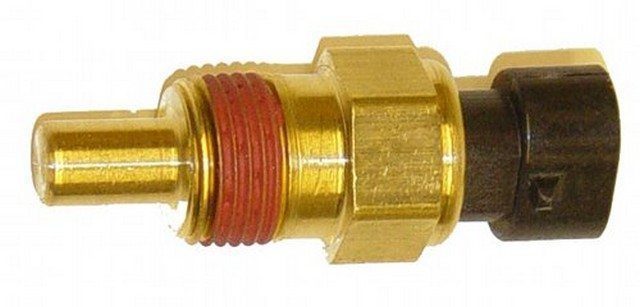
Role and Operation of the ECT Sensor

The Engine Coolant Temperature (ECT) sensor is a thermistor located in the engine block or a coolant passage. Its electrical resistance varies with the coolant temperature. It is typically a two-wire sensor: one receives a 5-volt reference voltage from the Powertrain Control Module (PCM), and the other serves as ground.

When the engine is cold, the sensor’s resistance is high. When it is hot, its resistance is low. The P0117 code is triggered when the PCM detects an abnormally low signal voltage, indicating an excessively “hot” condition.

Engine Coolant Temperature ECT Sensor
Example of an ECT Sensor

Symptoms of the P0117 Code

  • Malfunction Indicator Lamp (MIL) illuminated
  • Poor fuel economy
  • Engine misfiring or stalling
  • Rough or impossible idling
  • Black smoke from the exhaust
  • Hard starting or stalling after starting

Possible Causes

  • Faulty ECT sensor
  • Short to ground in the signal circuit
  • Oxidized, damaged, or loose connectors
  • Damaged or chafed wiring harness
  • 5V reference issue from the PCM
  • Engine overheating (rare)
  • Faulty PCM (very rare)

Diagnosis and Solutions

The P0117 code indicates an abnormal “hot” condition. The first step is to determine whether the problem is with the sensor, the wiring, or, more rarely, actual overheating.

Step 1: Verification with a Diagnostic Tool

With the ignition on (engine off, KOEO), observe the ECT sensor temperature reading on the diagnostic tool. On a cold engine, it should be close to ambient temperature and match the Intake Air Temperature (IAT) sensor reading. A significant discrepancy indicates a likely issue with the ECT sensor.

Step 2: Testing the Sensor and Wiring

If the reading shows an excessively hot temperature (e.g., > 125°C), disconnect the ECT sensor connector. The reading on the diagnostic tool should drop to an extreme cold value (e.g., -40°C).

  • If the reading drops: The ECT sensor has an internal short circuit. It must be replaced.
  • If the reading does not change: There is a short to ground in the wiring between the sensor and the PCM. Visually inspect the harness for signs of wear, chafing, or melting. Repair or replace the damaged wiring.

Step 3: Checking the 5V Reference Circuit

If the wiring appears intact, check the voltage at the signal wire pin on the PCM connector. An absent or low voltage may indicate a PCM issue or a short on the 5-volt reference circuit shared with other sensors. If other sensor codes are present, disconnect the sensors one by one to identify the one causing the short.

Step 4: Intermittent Issue

If the reading seems normal, the problem may be intermittent. Shake the wiring harness and manipulate the connectors while monitoring the ECT reading. Use the “freeze frame data” function of your diagnostic tool to see the value recorded at the time of the fault.

Related Codes

P0115, P0116, P0118, P0119, P0125, P0128

🔧 Need Help?

Electrical diagnosis can be complex. If you are not comfortable using a multimeter or a scan tool, consult a professional mechanic for an accurate diagnosis and to avoid damaging your PCM.

P0118 – Engine Coolant Temperature Circuit High Input

What is the P0118 Code?

The P0118 trouble code is a generic powertrain code. It indicates that the Powertrain Control Module (PCM) has detected an abnormally high voltage in the Engine Coolant Temperature (ECT) sensor circuit. This code applies to most vehicles built from 1996 onwards (Honda, Toyota, Volkswagen, Ford, BMW, etc.). Although generic, specific diagnostic procedures may vary by make and model.

ECT Sensor Operation

The ECT sensor is a thermistor located in a coolant passage, typically on the engine cylinder head. Its principle is simple: its electrical resistance is high when the engine is cold and decreases as the coolant temperature rises.

The PCM sends a 5-volt reference voltage to the sensor and monitors the return voltage. This measurement allows it to calculate the temperature in real-time. If the received signal indicates a constantly very low temperature (below freezing) when the engine is hot, or if the resistance is out of specifications, the PCM logs the P0118 code and illuminates the Malfunction Indicator Lamp (MIL).

Photo of an Engine Coolant Temperature (ECT) sensor
Example of an Engine Coolant Temperature (ECT) sensor

Symptoms of the P0118 Code

A fault in the ECT sensor circuit can cause several symptoms:

  • Poor fuel economy: The PCM, receiving incorrect information, excessively enriches the air-fuel mixture.
  • 🚗 Starting problems: Difficulty starting when cold or hot.
  • Poor engine performance: Rough idle, hesitation, misfires, and black smoke emissions.
  • ⚠️ Warning light: Illumination of the check engine light on the dashboard.

Possible Causes of the Fault

Several elements can be the cause of the P0118 code:

  • 🔌 Connection problem: Loose, corroded, or oxidized sensor connector.
  • Circuit problem: Short to voltage in the signal wire between the sensor and the PCM, or an open ground circuit.
  • 🔧 Faulty sensor: Internally shorted ECT sensor (most common cause).
  • 🤖 PCM failure: An internal problem with the control module is rare but possible.

Diagnosis and Solutions

To diagnose and resolve a P0118 code, follow this step-by-step procedure:

1. Verification with a Diagnostic Tool

Connect an OBD2 scan tool and observe the live temperature value displayed. If it is logical (increases gradually as the engine warms up), the problem is likely intermittent. Wiggle the sensor harness and connector while monitoring the scan tool. A sudden drop in the reading confirms a bad connection.

2. Sensor Test

If the reading is illogical (e.g., constant -40°C), unplug the sensor and measure its resistance with a multimeter. Compare the measured value to the manufacturer’s specifications for ambient temperature. An out-of-spec resistance indicates a faulty sensor that needs replacement.

3. Circuit Test

If the sensor seems good, the problem is in the circuit. With the engine off, disconnect the sensor connector. Using a jumper wire, short the two pins of the connector on the harness side. If the scan tool now displays a very high temperature (above 120°C), the circuit and PCM are functional, confirming the sensor is faulty.

4. Voltage and Ground Check

With the ignition on, use the multimeter to check for the presence of the 5V reference voltage and a good ground at the sensor connector (wires disconnected).

  • If the 5V and ground are absent at the connector, check for their presence directly at the PCM connector.
  • If they are present at the PCM, there is a break or short in the wiring that needs repair.
  • If the 5V is absent at the PCM even after disconnecting the connector, the PCM is likely faulty.

Important Note: Although a bad sensor is the most common cause of the P0118 code, it is essential to check the circuit before replacing it to avoid an ineffective repair. If you are not comfortable with these electrical procedures, entrust the diagnosis to a professional mechanic.

Related Codes

Codes related to the engine coolant temperature sensor circuit: P0115, P0116, P0117, P0119, P0125, P0128.

💡 Need help? Can’t resolve the P0118 code on your vehicle? Share your measurements and symptoms in the comments or consult a partner garage for a professional diagnosis.

Engine Coolant Temperature Sensor Circuit Intermittent

Definition of Code P0119

The trouble code P0119 is a generic OBD-II code from the powertrain group. It indicates a problem with the Engine Coolant Temperature (ECT) sensor circuit, manifesting as an intermittent or erratic signal sent to the engine control module (PCM or ECU).

Role of the Engine Coolant Temperature Sensor

  • Function: Precisely measure the coolant temperature to allow the PCM to regulate essential functions:
    • The air-fuel mixture (rich when cold, lean when hot).
    • Ignition timing.
    • Idle speed.
    • Activation and speed of the cooling fan.
    • Regeneration of the diesel particulate filter (DPF) or EGR valve on some engines.
  • Technical Principle: It is a Negative Temperature Coefficient (NTC) thermistor. Its electrical resistance decreases as the coolant temperature increases. The PCM sends a reference voltage (usually 5V) and interprets the returned voltage to determine the temperature.
  • Sensor Types:
    • 2-wire: Reference voltage (5V) and ground (signal for the PCM).
    • 3-wire: Adds a dedicated wire to power the dashboard gauge.

Symptoms of Code P0119

  • 🚨 Check Engine Light illuminated (MIL) on the dashboard.
  • ❄️ Very unstable idle, especially during a cold start.
  • ⚠️ Hesitation, stumbling, and power loss during acceleration.
  • Excessive fuel consumption and smell of gasoline (overly rich mixture).
  • 🌡️ Cooling system malfunction: Cooling fan running continuously or not at all, risk of engine overheating.
  • ⚠️ Difficulty starting in cold weather.

Possible Causes of Code P0119

Electrical and Mechanical Problems

  1. Faulty ECT Sensor: The thermistor is damaged, providing a resistance value outside the manufacturer’s specifications.
  2. Wiring Problems:
    • Cut, frayed, or chafed electrical wires.
    • Short circuits or faulty ground connections.
    • Oxidized, loose, or corroded connectors (caused by coolant leaks).
  3. Low Coolant Level: A leak in the system can prevent the sensor from being properly immersed, skewing its reading.
  4. Faulty Thermostat: If it remains stuck open, the engine never reaches its optimal operating temperature, disrupting the system.
  5. Problem with the PCM: Although rare, an internal fault in the control module can be the cause.

Diagnosis and Repair Procedure

Required Tools

  • OBD2 scanner to read codes and live data.
  • Digital multimeter (DVOM) to measure resistance and voltage.
  • Infrared thermometer to check the actual engine temperature.
  • Basic tool kit, coolant, and contact cleaner spray.

Diagnostic Steps

  1. Preliminary Checks: Check the coolant level and condition. Look for any obvious signs of leaks.
  2. Visual Inspection: Carefully inspect the ECT sensor wiring and connector along their entire length. Look for physical damage, corrosion, or loose pins. Clean the connectors.
  3. Test with OBD2 Scanner:
    • Read the live data. Compare the temperature value displayed by the sensor with the actual engine temperature measured with the infrared thermometer on the thermostat or radiator.
    • A significant discrepancy or an erratic, jumping value indicates a problem.
  4. Electrical Tests (engine cold and disconnected):
    • Resistance Test: Measure the resistance between the sensor pins. Compare it to the manufacturer’s reference values (e.g., ~2000-3000 Ω at 20°C). An infinite value (open circuit) or zero (short circuit) confirms a faulty sensor.
    • Voltage Test: Reconnect the connector, ignition on. Measure the voltage between the signal wire and ground. It should be around 3V when cold and gradually decrease as the engine warms up.

Repair

  • Replacing the ECT Sensor:
    1. Locate its position (usually on the engine block, cylinder head, intake manifold, or thermostat housing).
    2. Turn the ignition OFF. Disconnect the electrical connector.
    3. Carefully unscrew the old sensor. A small coolant leak is normal; catch it.
    4. Screw in the new sensor (use a new seal if necessary). Reconnect the connector.
  • Repairing the Wiring: Solder and use heat-shrink tubing or replace damaged wire sections.
  • Refilling Coolant: After replacement, top up the level with the appropriate mixture (often 50/50) and bleed the system of air.

Validating Repairs

  1. Clear the trouble codes with the scanner.
  2. Start the cold engine and let it warm up to normal operating temperature.
  3. Monitor the scanner data: the temperature should rise progressively and stabilize around 90°C.
  4. Perform a road test to verify that the symptoms (unstable idle, hesitation) have disappeared and that the Check Engine Light does not come back on.

Important Recommendations and Precautions

  • 🔧 Priority: Do not ignore this code. A faulty signal can lead to severe overheating, damage the catalytic converter, and increase engine wear.
  • ⚠️ Quality Parts: Prefer OEM quality or reputable brand sensors. Low-end parts often have an imprecise resistance curve and can cause the code to reappear.
  • 🧤 Safety: Never open a radiator cap on a hot engine. Risk of severe burns. Handle coolant with gloves.
  • 📄 Related Codes: Also diagnose codes P0115, P0116, P0117, or P0118 if present, as they relate to the same circuit.

💡 Need Help? This diagnosis can be complex. If you are unsure, consult a professional or use a platform like AllDataDIY to access wiring diagrams and procedures specific to your vehicle model.

References: Always consult your vehicle’s repair manual for precise resistance values and specifications.

P011A Engine Coolant Temperature Sensor Correlation 1/2

Code P011A: Definition and Explanations

The P011A trouble code is a generic powertrain code found in most OBD-II vehicles (Mazda, Land Rover, GMC, Chevrolet, Ford, Dodge, Chrysler, Toyota, Honda, etc.). It indicates that the Powertrain Control Module (PCM) has detected an inconsistency between the signals from two Engine Coolant Temperature (ECT) sensors, often referred to as Sensor A and Sensor B (or primary and secondary). This code only appears on engines equipped with multiple ECT sensors.

ECT Sensor Operation

An Engine Coolant Temperature (ECT) sensor is a thermistor whose resistance varies with temperature. It is typically housed in a metal or plastic casing and installed in the engine block, cylinder head, intake manifold, or radiator.

When the coolant temperature increases, the sensor’s resistance decreases, causing an increase in the signal voltage sent to the PCM. The PCM uses this data to regulate the air-fuel mixture, idle speed, cooling fan operation, and sometimes the dashboard display.

Severity Level of Code P011A

This code is considered severe. A correlation fault between the ECT sensors can lead to poor engine management, overheating, increased fuel consumption, or higher pollutant emissions. It is recommended to perform diagnostics promptly.

Symptoms of Code P011A

  • Air-fuel mixture too rich or too lean
  • Irregular idle (especially when cold)
  • Decreased engine performance
  • Increased fuel consumption
  • Illumination of the Malfunction Indicator Lamp (MIL)

Possible Causes of Code P011A

  • Faulty ECT sensor
  • Damaged sensor wires or connectors (short circuit or open circuit)
  • Insufficient coolant level
  • Faulty thermostat (stuck open or closed)
  • Defective water pump
  • Air pocket in the cooling system
  • PCM failure or programming error

Diagnostic Procedure for Code P011A

Required Tools

For effective diagnostics, it is recommended to have an OBD2 scanner, a digital multimeter (DVOM), and manufacturer technical data (wiring diagrams, resistance values).

Steps to Follow

  1. Cooling System Check: Check the coolant level and condition. Verify the proper operation of the thermostat, water pump, and fans. Bleed the system if there are air pockets.
  2. Visual Inspection: Examine the ECT sensor connectors and wiring for any signs of corrosion, damage, or disconnection.
  3. Reading Codes and Live Data: Using the scanner, retrieve all trouble codes and freeze frame data. Note this information, clear the codes, and perform a road test to see if P011A reappears.
  4. ECT Sensor Testing: When cold, measure the sensor resistance with a multimeter and compare it to the manufacturer’s specified values. A sensor outside specifications should be replaced.
  5. Electrical Circuit Testing: Check for continuity and the absence of short circuits in the wires connecting the sensors to the PCM. Look for a reference voltage supply (typically 5V) and a good ground.
  6. PCM: A PCM module failure or the need for a software update should only be considered as a last resort, after all other possible causes have been eliminated.

Important Diagnostic Notes

  • ⚠️ Safety: Never open the radiator cap on a hot engine. The system is under pressure and can cause serious burns.
  • 🔌 Electrical Precautions: Always disconnect the sensor connector before measuring its resistance with a multimeter.
  • 📄 Technical Bulletins: Consult your vehicle’s Technical Service Bulletins (TSB), as some manufacturers may have released software fixes for this issue.

Conclusion and Call to Action

Code P011A indicates a correlation problem between the engine coolant temperature sensors. Although diagnostics can be performed by an experienced DIYer, the complexity of modern systems often makes intervention by a professional safer and more effective.

Need help diagnosing or repairing this trouble code? Consult a qualified mechanic or a specialized garage for accurate diagnostics and reliable repairs.

P011B Correlation Between Coolant and Air Temperature

Code P011B: Definition and Meaning

The error code P011B is a generic powertrain code found on all vehicles equipped with the OBD-II standard (Toyota, Honda, Ford, GMC, etc.). It indicates that the Powertrain Control Module (PCM) has detected an inconsistency or incorrect correlation between the signals from the Engine Coolant Temperature (ECT) sensor and the Intake Air Temperature (IAT) sensor.

Operation of ECT and IAT Sensors

The ECT sensor is a thermistor housed in a metal or plastic casing, screwed into the engine block or cylinder head. Its resistance decreases as the coolant temperature increases, which the PCM interprets to regulate the air-fuel mixture, idle speed, and fan activation.

The IAT sensor operates on the same principle but measures the temperature of the air entering the intake. It is typically located in the air filter housing or the intake duct.

Code P011B is triggered when the signals from these two sensors show an abnormal deviation, as predefined by the manufacturer.

Severity Level of Code P011B

This fault is considered moderate to serious. Prolonged driving with this code active can damage the catalytic converter, increase fuel consumption, and degrade performance. It is recommended to perform a diagnosis promptly.

Symptoms of Code P011B

  • Unstable idle, especially when cold
  • Reduced performance and sluggish acceleration
  • Increased fuel consumption
  • Rich or lean exhaust mixture
  • Illumination of the check engine light (MIL)
  • Other temperature-related codes

Possible Causes of Code P011B

  • Faulty ECT or IAT sensor
  • Damaged wires or connectors (short circuit, corrosion)
  • Low coolant level
  • Faulty thermostat (stuck open or closed)
  • Inefficient water pump
  • Air pocket in the cooling system
  • PCM failure or need for update

Diagnosis and Troubleshooting of Code P011B

To diagnose this code, you will need an OBD2 scanner, a digital multimeter (DVOM), and your vehicle’s technical data.

Steps to Follow:

  1. Cooling System Check: Check the level and condition of the coolant. Bleed the system to remove any air pockets. Ensure the thermostat, water pump, and radiator are functioning correctly.
  2. Visual Inspection: Examine the connectors and wiring of the ECT and IAT sensors for any signs of corrosion, damage, or poor contact.
  3. Reading Codes and Data: Use your scanner to read all fault codes and freeze frame data. Note this information before clearing the codes.
  4. Sensor Testing: Using the multimeter, measure the resistance of the ECT and IAT sensors (with the engine cold and then hot) and compare them to the manufacturer’s specified values. A sensor out of specification should be replaced.
  5. Circuit Testing: If the sensors are good, test the electrical circuits (voltage, continuity) between the sensors and the PCM.
  6. PCM Verification: If everything else is in order, a PCM failure or programming error is plausible. Consult your manufacturer’s Technical Service Bulletins (TSB).

Important Notes and Pro Tips

  • The IAT sensor is often forgotten or improperly reconnected after an air filter replacement.
  • Always disconnect the sensor connector before measuring its resistance with a multimeter.
  • Handle the cooling system with caution, when the engine is cold, to avoid burns.
  • Always consult Technical Service Bulletins (TSB) for your model, as known issues may exist.

Need help diagnosing your vehicle? Consult a qualified mechanic for an accurate diagnosis if you are not comfortable with these procedures.

P011C Charge Air / Intake Air Temperature Sensor 1 Correlation

What is the P011C Code?

The P011C error code is a generic OBD-II powertrain code. It indicates that the Powertrain Control Module (PCM) has detected an abnormal difference between the signals from the Charge Air Temperature (CAT) sensor and the Intake Air Temperature (IAT) sensor for engine bank 1.

Symptoms of the P011C Code

When this fault code is stored, you may observe one or more of the following symptoms:

  • Noticeable decrease in engine performance
  • Air-fuel mixture too rich or too lean
  • Hard starting, especially when cold
  • Reduced fuel efficiency (increased consumption)
  • Possible illumination of the Malfunction Indicator Lamp (MIL)

Possible Causes of the Fault

Several factors can cause the P011C code:

  • Sensor failure (CAT or IAT)
  • Wiring problem (short circuit or open circuit) on the sensors
  • Defective, corroded, or loose connectors
  • Clogged or damaged intercooler
  • Software issue or internal PCM failure

How to Diagnose the P011C Code

Diagnosis requires an OBD2 scanner, a digital multimeter (DVOM), and the vehicle’s technical data.

Diagnostic Steps:

  1. Visual Inspection: Check the condition of the CAT and IAT sensor connectors and wiring. Ensure the air filter is clean and there are no obstructions in the intercooler.
  2. Code Reading: Use the scanner to read all fault codes and record the freeze frame data.
  3. Clearing and Retest: Clear the codes and perform a road test to see if the P011C code returns.
  4. Sensor Testing: If the code reappears, test the resistance of the CAT and IAT sensors (engine off, sensors disconnected) with a multimeter. Compare the measured values with the manufacturer’s specifications.
  5. Circuit Testing: Check for the presence of reference voltage (5V) and ground at the sensor connectors. Test the signal from each sensor (engine running) and compare it to reference curves.
  6. PCM Verification: If all sensors and circuits are within specifications, a programming error or PCM failure is suspected. Consult technical service bulletins (TSB) for the vehicle.

Conclusion and Call to Action

The P011C code is a serious fault that should not be ignored, as it directly affects performance and fuel economy. Accurate diagnosis is essential to avoid unnecessary part replacement.

Need help diagnosing this code on your vehicle? Consult a qualified mechanic or use our tool to get model-specific advice.

P011D Charge Air Temperature / Intake Air Temperature Correlation Bank 2

What is the P011D Code?

The P011D trouble code is a generic OBD-II powertrain code. It indicates that the Powertrain Control Module (PCM) has detected an abnormal difference between the signals from the Charge Air Temperature sensor (CAT) and the Intake Air Temperature sensor (IAT) for engine bank 2.

This code specifically applies to vehicles equipped with forced air induction systems (turbocharger or supercharger) and multiple air intakes (throttle bodies). Bank 2 refers to the side of the engine that does not contain cylinder number 1.

Symptoms of the P011D Code

Common symptoms include:

  • Reduced engine performance
  • Air-fuel mixture too rich or too lean
  • Hard starting (particularly when cold)
  • Decreased fuel efficiency
  • Illumination of the check engine light (MIL)

Possible Causes of the P011D Code

The main causes of this fault are:

  • Sensor failure (CAT or IAT)
  • Wiring or connector issue (short circuit or open circuit)
  • Clogged or faulty intercooler
  • PCM failure or programming error

Diagnosis and Troubleshooting of the P011D Code

Diagnosis requires an OBD2 scanner, a digital multimeter (DVOM), and the vehicle’s technical data.

Diagnostic Steps:

  1. Visual Inspection: Check the condition of the air filter, ensure the intercooler is not obstructed, and inspect the condition of the sensor wiring/connectors.
  2. Code Reading: Use the scanner to read all trouble codes and freeze frame data. Note this information before clearing the codes.
  3. Sensor Testing:
    • Disconnect the CAT and IAT sensors
    • Measure their resistance with a multimeter and compare to manufacturer specifications
    • Replace any sensor that is out of specification
  4. Circuit Testing:
    • Check for the presence of reference voltage (5V) and ground at the connectors
    • Test the signal circuit with the engine running and compare with expected values
  5. PCM Verification: If all components are good, suspect a PCM failure or consult manufacturer technical bulletins.

Important Tip:

The IAT sensor is sometimes forgotten after an air filter replacement. Verify that it is properly connected.

Conclusion

The P011D code directly affects engine performance and should be addressed promptly. Although the described steps cover the main causes, the complexity of modern systems may require intervention from a professional equipped with specialized diagnostic tools.

⚠️ Need help with this trouble code? Consult a qualified mechanic for an accurate diagnosis or search for technical bulletins specific to your vehicle.

P011E, P011F ISO/SAE Reserved

Before diagnosing a reserved ISO/SAE error code such as P011E or P011F, it is essential to understand that it often involves non-compliance with strict technical standards rather than a direct hardware failure. These standards are established by two major organizations: the Society of Automotive Engineers (SAE) and the International Organization for Standardization (ISO).

ISO and SAE: Definition and Roles

  1. SAE (Society of Automotive Engineers)
    Founded in 1905 in the United States, SAE develops standards for the automotive and aerospace industries. The SAE acronym is also recognized for designating tools and components with non-metric standard dimensions.
  2. ISO (International Organization for Standardization)
    Established in 1947, ISO brings together standardization bodies from over 100 countries. Its mission is to harmonize international standards to promote trade and technological innovation, particularly in data communication and information technologies.

Importance of ISO/SAE Standards in the Automotive Industry

Since 1995, manufacturers have collaborated with ISO and SAE to define strict guidelines for on-board diagnostic (OBD) systems and data communication. These standards aim to:

  • Reduce electromagnetic interference,
  • Standardize communication protocols,
  • Minimize message conflicts between systems.

Protocols Subject to ISO/SAE Standards

The main standardized automotive protocols include:

  • CAN bus: A multiplexed network enabling communication between the PCM and other controllers.
  • DC bus, Keyword Protocol, LIN network, and VAN: Manage non-critical functions such as entertainment or comfort.

The CAN bus is particularly crucial, as a modern vehicle can have up to 70 interconnected controllers. An interface error detected in this network generates an ISO/SAE code and may illuminate the Malfunction Indicator Lamp (MIL).


Severity and Symptoms of ISO/SAE Codes

Severity Level

The conditions causing an ISO/SAE code vary significantly:

  • Serious issues affecting driving.
  • Minor malfunctions with no immediate impact.

Common Symptoms

  • Vehicle handling problems.
  • No visible symptoms at all.
  • Presence of other associated OBD-II codes.

Possible Causes

  • Damaged or corroded wiring or connectors.
  • Failure of an on-board controller (ECU).
  • Controller programming or software error.

Diagnostic Procedure for ISO/SAE Codes

  1. Initial Check
    • Visually inspect cables and connectors for any damage or corrosion.
    • Check battery charge and proper alternator function.
  2. Code Analysis with an OBD2 Scanner
    • Connect a diagnostic scanner to the OBD-II port to read codes and freeze frame data.
    • Clear the codes and test the vehicle to check if the error is intermittent.
  3. In-Depth Inspection
    • If the code reappears, consult the manufacturer’s Technical Service Bulletins (TSB).
    • Perform a wiggle test to check the stability of CAN bus connectors and wiring.
  4. Hardware or Software Fault
    • If no issues are detected, suspect a faulty controller or a programming error requiring a software update.

Examples of Reserved ISO/SAE Codes

Here is a non-exhaustive list of common codes: P011E, P012F, P015E, P015F, P016A-P016F, P017A-P017F, P019A-P01FF, P030A-P030F, P033F, P034A-P034F, P038A-P038F, P0000, P00C0-P00FF.

Conclusion and Call to Action

Diagnosing ISO/SAE codes like P011E or P011F requires a methodical approach, ranging from basic wiring checks to the use of advanced scanning tools. If you are not equipped or familiar with these procedures, consult a professional mechanic or a garage specialized in automotive diagnostics for an effective and safe resolution of the issue.

P0120 TPS Circuit A Malfunction

What is the P0120 trouble code?

The P0120 code is a generic OBD-II (On-Board Diagnostics) code indicating a malfunction in the Throttle Position Sensor (TPS) A circuit. This sensor, essential for proper engine operation, sends incorrect data to the Powertrain Control Module (PCM), which can affect vehicle performance.

Function of the Throttle Position Sensor (TPS)

The TPS is a potentiometer mounted on the throttle body. It measures the throttle plate’s opening angle and transmits this information in real-time to the PCM via an electrical signal. This signal allows the PCM to precisely adjust the air-fuel mixture and ignition timing.

The sensor is typically powered by a 5-volt reference voltage from the PCM and returns a variable signal:

  • Throttle closed (idle): ~0.45V
  • Wide Open Throttle (WOT): ~4.5V to 5V

The PCM can compare TPS data with that from the Manifold Absolute Pressure (MAP) sensor to check for consistency. An inconsistency can trigger the P0120 code.

Symptoms of the P0120 Code

Illumination of the Malfunction Indicator Lamp (MIL) is the most obvious symptom. Other signs may include:

  • Misfires at idle or cruising speed
  • Irregular or unstable idle
  • Stalling, especially during acceleration
  • Difficulty starting
  • Noticeable decrease in performance and responsiveness

Possible Causes of the P0120 Code

Several components can be the source of this fault:

  • Faulty TPS Sensor: The most common cause (internal wear, dead spot).
  • Connection Issues: Corroded, loose, or oxidized TPS or MAP sensor connector.
  • Wiring Problems: Damaged harness wires, chafing, short circuit, or open circuit.
  • Mechanical Problem: Sticking throttle plate or its return spring.
  • Faulty PCM: A rare cause, to be considered after ruling out all other possibilities.

Diagnosis and Solutions for Fixing P0120

⚠️ Warning: This information is for guidance only. For an accurate diagnosis, consult a professional mechanic.

1. Checking with a Diagnostic Tool

With the key in the ON position (engine off – KOEO), use a scan tool to observe the live TPS voltage. It should be around 0.45V at idle and increase progressively and smoothly to ~5V at full throttle. A stuck, erratic, or out-of-range voltage indicates a problem.

2. Visual Inspection

Inspect the TPS connector and wiring for obvious signs of damage, corrosion, or debris. Check the harness routing to avoid chafing.

3. Electrical Tests (DVOM)

Disconnect the connector and, with the engine off, check for the presence of the 5V reference voltage and a good ground. Test for continuity and the absence of a short circuit on the signal wire. Wiggle the harness during measurement to detect intermittent problems.

4. Replacement and Calibration

If tests point to a faulty sensor, replace it. Important Note: On some vehicles, the new TPS requires precise calibration (adjusting the voltage to 0.45V at idle). Refer to the specific repair manual for your model.

5. Diagnostic Conclusion

  • If the TPS voltage becomes normal after replacement: problem solved.
  • If the reading remains abnormal after replacement: check the wiring between the TPS and PCM.
  • If the wiring is intact, an internal PCM issue is possible but rare.

Related Trouble Codes

Other TPS-related codes may appear: P0121, P0122, P0123, P0124.

Call to Action

Electrical diagnosis requires experience and the right tools. If you are unsure of your diagnosis, entrust your vehicle to a professional mechanic. They will have the necessary tools (oscilloscope, advanced scanner) to identify and resolve the problem effectively, saving you from unnecessary costly repairs.

P0121 Throttle/Pedal Position Sensor/Switch A Circuit Range/Performance Problem

What is the P0121 code?

The P0121 error code is a generic OBD-II code related to the powertrain. It indicates a problem with the range or performance of the Throttle Position Sensor (TPS) circuit. This sensor, a potentiometer, monitors the throttle plate opening angle and sends an electrical signal to the Powertrain Control Module (PCM).

The PCM supplies a 5-volt reference voltage to the sensor. The TPS output voltage varies depending on the accelerator pedal position: approximately 0.5 V at idle and up to 4.5 V at wide-open throttle. The P0121 code is triggered when the PCM detects a voltage value that is inconsistent or outside the predefined ranges for the engine speed.

Symptoms of the P0121 code

The illumination of the Malfunction Indicator Lamp (MIL) is the most obvious symptom. Other signs may accompany this code:

  • Check Engine light on
  • Hesitation and stalling during acceleration or deceleration
  • Starting difficulties, or even inability to start
  • Black smoke from the exhaust during acceleration
  • Noticeable decrease in performance and engine torque
  • Unstable or irregular idle

Possible causes of the P0121 fault

Several components can be the source of this error code:

  • A faulty Throttle Position Sensor (TPS) (internal failure)
  • Damaged wiring: chafed, cut, shorted, or open wires
  • Poor electrical connections at the TPS connector
  • The presence of moisture or corrosion in the connector
  • Loss of ground or the 5V reference signal
  • A problem with the PCM module (less common)

Diagnosis and solutions to fix the P0121 code

Here is a step-by-step diagnostic procedure to identify and resolve the fault.

1. Verification with a diagnostic tool

Using an OBD2 diagnostic tool, observe the live data from the TPS sensor. Check that the value at idle is close to 0.5 V and that it increases progressively to about 4.5 V when you slowly press the accelerator. An erratic reading, out of specification, or one that does not change linearly indicates a problem.

2. Visual inspection

Disconnect the sensor connector and inspect it carefully. Look for signs of corrosion, bent pins, or moisture. Visually inspect the wiring harness for any exposed, cut, or chafed wires rubbing against a component.

3. Electrical tests with a multimeter

For an accurate diagnosis, use a multimeter:

  • Reference Voltage (5V): Turn the ignition on and measure the voltage between the reference pin and ground. It should be a stable 5V.
  • Ground: Check the continuity between the ground pin and the chassis ground.
  • Signal: Measure the signal voltage between the signal pin and ground. It should vary linearly and smoothly from ~0.5V to ~4.5V.

4. Oscilloscope test (recommended)

An oscilloscope is the ideal tool for detecting intermittent problems that diagnostic tools might miss. The signal should form a clean, regular curve, without spikes or dropouts when you operate the accelerator.

5. Wiggle test

Reconnect the sensor and, with the diagnostic tool in live data mode, wiggle the wiring harness and the connector. If the TPS value changes abruptly or becomes erratic, this confirms a connection or wiring problem.

Repair solutions

  • If the tests point to the sensor, replace the TPS sensor.
  • Clean the connectors and repair any damaged wiring.
  • If the reference voltage or ground is absent, look for an open or short circuit in the wiring harness.
  • After any repair, clear the codes and perform a road test to verify that the fault does not return.

Related DTC codes

Other codes related to the throttle position sensor circuit may appear: P0120 (Circuit Malfunction), P0122 (Signal Too Low), P0123 (Signal Too High), P0124 (Intermittent Signal).

⚠️ Tip: Electrical diagnosis requires specific skills. If you are not comfortable with these procedures, it is recommended to entrust the diagnosis to a professional automotive mechanic.