Mass Air Flow (MAF) B Circuit High

What is the P010D fault code?

The P010D fault code is a generic powertrain code (OBD-II) that indicates a problem with the Mass Air Flow (MAF) sensor “B” circuit. It means that the engine control module (PCM) has detected an abnormally high electrical signal from this sensor. This code affects many brands (Toyota, Ford, Audi, Mercedes, etc.), but the specific diagnostic procedures may vary from model to model.

Role of the MAF Sensor

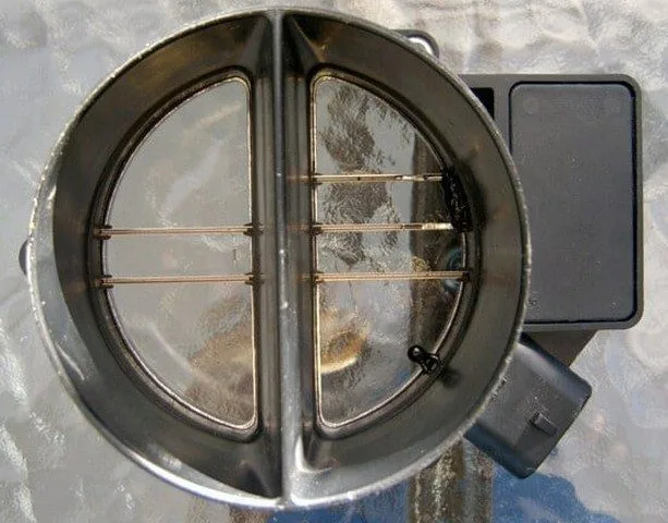
The MAF sensor (Mass Air Flow) is located in the intake duct, between the air filter and the manifold. It measures the volume and density of the air drawn into the engine. The PCM uses this essential data, along with other parameters, to calculate the amount of fuel to inject, thus ensuring an optimal air-fuel mixture for performance, fuel consumption, and emissions.

Symptoms of the P010D Code

  • Malfunction Indicator Lamp (MIL) illuminated (“Check Engine”)
  • Engine running rough or stalling
  • Hard starting
  • Hesitation during acceleration
  • Black smoke from the exhaust (overly rich mixture)
  • Sometimes, no noticeable symptoms are present

Potential Causes of the Fault

  • Dirty or contaminated MAF sensor (oil, dust)
  • Faulty or inoperative MAF sensor
  • Wiring problem: open circuit, short circuit, corroded or loose connector
  • Air leaks in the intake system (downstream of the sensor)
  • Excessively dirty air filter
  • Problem related to the MAP sensor (Manifold Absolute Pressure)

How to Diagnose and Repair a P010D Code?

Here is a step-by-step diagnostic procedure to identify and resolve the cause of the P010D code.

1. Visual Inspection

  • Inspect the MAF sensor’s wiring and connector for any signs of damage, corrosion, or poor contact.
  • Check the entire intake system to locate any potential air leaks (cracked hoses, faulty seals).

2. Cleaning the MAF Sensor

  • If the sensor is dirty, use a specific MAF sensor electrical cleaner. Gently spray it onto the filament or film without touching it. Let it dry completely before reinstalling it.
  • Take the opportunity to inspect and, if necessary, replace the air filter with an original part.

3. Advanced Diagnostics

  • Using an OBD2 diagnostic tool, monitor the MAF sensor’s live data at idle and during light acceleration. Compare the values with those specified by the manufacturer.
  • Check for other associated fault codes (P010A, P010B, P010C, P010E, oxygen sensor codes, etc.).
  • Consult your manufacturer’s Technical Service Bulletins (TSBs) for any known issues related to your vehicle model.

4. Replacement

  • If the fault persists after cleaning and checking the wiring, the MAF sensor is likely faulty.
  • Recommendation: For optimal reliability, prefer purchasing an OEM quality sensor (original equipment) rather than a cheap aftermarket part.

Need help? Accurate electrical diagnosis may require the expertise of a professional. If you are unsure of your diagnosis, consult a qualified mechanic to avoid unnecessary repairs.

P010E Mass Air Flow MAF B Circuit Intermittent

What is the P010E code?

The P010E trouble code is a generic powertrain code related to the Mass Air Flow (MAF) sensor’s Circuit B. It indicates that the Powertrain Control Module (PCM) has detected an intermittent or erratic signal from this sensor. This code affects many brands (Toyota, Ford, Audi, Mercedes, etc.), but diagnostic procedures can vary from model to model.

Role of the MAF Sensor

The Mass Air Flow (MAF) sensor is located in the intake duct, downstream of the air filter. It measures the volume and density of the air drawn into the engine. The PCM uses this data, along with other parameters, to calculate the amount of fuel needed for optimal combustion, thus ensuring power, efficiency, and low emissions.

Symptoms of the P010E Code

Common symptoms associated with this code include:

  • Illumination of the Malfunction Indicator Lamp (MIL)
  • Rough idling or stalling
  • Hard starting
  • Black smoke from the exhaust
  • Reduced performance and fuel economy
  • No visible symptoms (in some intermittent cases)

Potential Causes of the Fault

Several factors can cause the P010E code:

  • A dirty or contaminated MAF sensor from dust or oil
  • A faulty MAF sensor
  • Air leaks in the intake system
  • A wiring problem (frayed wires, corroded connector, short circuit)
  • A clogged air filter

How to Diagnose and Repair the P010E Code?

Follow these steps to diagnose the fault:

  1. Visual Inspection: Check the MAF sensor connector and wiring for any signs of wear, corrosion, or poor contact.
  2. Air Leak Check: Carefully inspect the intake duct and hoses to identify any leaks downstream of the sensor.
  3. Cleaning the MAF Sensor: Use a specific MAF sensor cleaner. This is a simple and inexpensive first repair step.
  4. Replacing the Air Filter: A new, clean air filter (preferably OEM) is essential for accurate measurements.
  5. Using a Diagnostic Tool: With a scan tool, observe the live data from the MAF sensor and the air temperature sensor to spot inconsistencies.
  6. Checking TSBs: Verify the existence of Technical Service Bulletins (TSBs) for your model, which may document known issues.

Repair Tip: If sensor replacement is necessary, always prefer an Original Equipment Manufacturer (OEM) part to ensure optimal compatibility and longevity.

Related Codes

Other codes related to the MAF sensor circuit may appear, such as P010A, P010B, P010C, and P010D.

⚠️ Need help diagnosing your vehicle? Consult a professional mechanic for an accurate diagnosis and reliable repair.

P010F MAF Sensor A / B Correlation

What is the P010F Code?

The P010F trouble code is a generic powertrain code indicating a correlation problem between the signals from the mass air flow (MAF) or volume air flow (VAF) sensors. This code specifically applies to vehicles equipped with multiple MAF/VAF sensors, often found on engines with multiple throttle bodies or air intakes. Affected brands include, among others, Audi, Chevrolet, Citroën, Dodge, GMC, Lexus, Mercedes-Benz, Peugeot, Ram, Toyota, and Volkswagen.

Operation and Symptoms of the P010F Code

The Powertrain Control Module (PCM) continuously compares data from the various sensors. If their values diverge beyond a predefined threshold, the P010F code is stored, and a malfunction indicator lamp (check engine) may illuminate.

Common Symptoms

  • Decreased engine performance and power
  • Noticeable reduction in fuel consumption (over-boosting)
  • Jerking, stalling, or hesitation during acceleration
  • Appearance of trouble codes related to lean (too much air) or rich (too much fuel) mixture
  • In severe cases, the vehicle may not start

Main Causes of the P010F Code

  • Faulty MAF or VAF Sensor: A sensor providing an incorrect reading.
  • Electrical Circuit Problems: Cut wires, corroded connectors, short circuits, or poor grounds.
  • Unmetered Air Leaks: A leak in the intake system draws in air that is not accounted for by the sensor.
  • Damaged Air Ducts: A cracked, detached, or punctured intake hose.
  • Dirty Sensor: A heating element (hot wire) fouled by dirt or debris.

Diagnosis and Repair Procedures

Diagnosis requires an OBD2 scanner, a digital multimeter (DVOM), and the vehicle’s technical data.

Steps to Follow

  1. Visual Inspection: Carefully inspect the wiring, connectors, and air ducts for damage, corrosion, or leaks. Clean any corroded connectors.
  2. Code Reading: Using the scanner, retrieve all fault codes and freeze frame data. Note them down before clearing them.
  3. Road Test: Perform a road test to see if the P010F code reappears.
  4. MAF Sensor Cleaning: If applicable, gently clean the MAF sensor filament with a specific cleaner. This step does not apply to VAF sensors.
  5. Electrical Tests: With a multimeter and a wiring diagram, test the power supply, ground, and signal of each sensor. Compare the values to the manufacturer’s specifications.
  6. Leak Check: Inspect the entire intake system to find and repair any unmetered air leaks.

Important Notes

  • Check and replace the air filter if necessary.
  • Consult your vehicle’s Technical Service Bulletins (TSB) for known issues.
  • Repairing any air leak is a crucial step before condemning a sensor.

Conclusion

The P010F code indicates a discrepancy between the sensors measuring the intake air flow. Its severity is medium to high, potentially affecting drivability and fuel consumption. A methodical diagnosis, starting with a visual inspection and cleaning of connectors, often resolves the issue without replacing expensive parts.

Need help diagnosing this code on your vehicle? Consult a professional mechanic or visit our help forum to share your scanner data and get targeted advice.

P0110 Intake Air Temperature Sensor 1 Circuit Malfunction

What is the P0110 Code?

The P0110 error code is a generic OBD-II code related to the powertrain. It indicates a malfunction in the Intake Air Temperature (IAT) sensor circuit, sensor 1. This code signals that the Powertrain Control Module (PCM) has detected an abnormal voltage from the IAT sensor, outside its normal operating range.

Role and Operation of the IAT Sensor

The Intake Air Temperature (IAT) sensor is a thermistor. Its electrical resistance varies depending on the temperature of the air it measures. It is typically located in the air intake duct or the intake manifold.

The PCM sends a 5-volt reference voltage to the sensor. When the air temperature changes, the sensor’s resistance varies, thus altering the signal voltage returned to the PCM. The PCM interprets this voltage to calculate the air temperature. Cold air causes higher resistance and voltage, while hot air causes lower resistance and voltage.

Symptoms of the P0110 Code

  • Malfunction Indicator Lamp (MIL) illuminated on the dashboard.
  • Incorrect air-fuel mixture ratio.
  • Reduced engine power.
  • Increased fuel consumption.
  • Irregular idle.
  • In some cases, no noticeable symptoms are apparent.

Possible Causes of the P0110 Code

  • Faulty IAT Sensor: The sensor itself is out of service.
  • Electrical Circuit Problem: Short to ground or power, open circuit, damaged wires.
  • Faulty Connector: Corroded, loose terminals, or damaged connector.
  • Improperly Installed Sensor: The sensor is dislodged and no longer in the airflow.
  • PCM Problem: Internal failure of the control module (rare).

Diagnosis and Solutions to Fix P0110

Preliminary Checks

  1. Visual Inspection: Check that the IAT sensor is properly installed in its housing and that no air ducts are loose or punctured.
  2. Connector Check: Inspect the sensor’s electrical connector for any signs of corrosion, damage, or loose wires.

Testing with a Diagnostic Tool

  1. Turn the ignition on (KOEO – Key On Engine Off) with the engine cold.
  2. Using your diagnostic tool, compare the values of the IAT sensor and the Coolant Temperature Sensor (CTS). They should be very similar (within a few degrees).
  3. If the IAT value displays an extreme temperature (e.g., -40°C or +300°C), this confirms a problem.

Electrical Testing of the Sensor

  1. Disconnect the IAT sensor connector.
  2. Using a multimeter in ohmmeter mode, measure the resistance between the two pins of the sensor.
  3. Compare the measured value with the manufacturer’s specifications (available in a repair manual). An infinite resistance (open circuit) or zero resistance (short circuit) indicates a faulty sensor that needs replacement.

Advanced Circuit Diagnosis

If the reading is extremely high (~300°C):

  1. Disconnect the sensor. If the reading changes to an extremely low value (~-50°C), replace the IAT sensor.
  2. If the reading does not change, check for a short to ground on the signal wire using a multimeter. If there is continuity to ground, repair the wire.

If the reading is extremely low (~-50°C):

  1. Disconnect the sensor and check for the presence of the 5V reference and a good ground at the vehicle connector.
  2. If the 5V and ground are present, short the two pins of the vehicle connector. If the reading on the diagnostic tool changes to an extremely high value, replace the sensor.
  3. If the 5V is absent, check the circuit up to the PCM for a break.

Related DTC Codes

P0095, P0096, P0097, P0098, P0099, P0111, P0112, P0113, P0114, P0127

Conclusion and Call to Action

The P0110 code is often resolved by replacing the IAT sensor, a component that is generally inexpensive. However, a thorough check of the electrical circuit is essential to avoid replacing a component unnecessarily.

Don’t have a diagnostic tool or don’t feel comfortable with these procedures? Entrust the diagnosis to a professional mechanic. They can quickly identify and resolve the problem, ensuring your vehicle functions properly.

P0111 Intake Air Temperature Sensor 1 Circuit Malfunction

What is the P0111 Code?

The P0111 trouble code is a generic OBD-II powertrain code that indicates a malfunction in the IAT (Intake Air Temperature) sensor circuit. This sensor is crucial for proper engine operation, as it allows the Powertrain Control Module (PCM) to adjust the air-fuel mixture based on the temperature of the incoming air.

IAT Sensor Operation

The IAT sensor is a thermistor whose electrical resistance changes with the air temperature. It typically consists of two wires: one supplied with a 5-volt reference voltage from the PCM, and the other connected to ground. The PCM monitors the voltage drop across this circuit to determine the temperature.

  • Cold Air: High resistance → High signal voltage.
  • Hot Air: Low resistance → Low signal voltage.

The P0111 code is triggered when the PCM detects an abnormal, too rapid, or extreme variation in this voltage.

Symptoms of the P0111 Code

This code often indicates an intermittent problem. Symptoms may be absent or subtle:

  • Malfunction Indicator Lamp (MIL) illuminated.
  • Possible reduction in engine performance.
  • Increased fuel consumption.
  • Hesitation or rough idle in some cases.

Possible Causes

Several factors can cause the P0111 code:

  • 🔧 Faulty IAT Sensor (most common cause).
  • Electrical Problem: Open circuit or short to ground on the signal wire.
  • 🔌 Poor Connection: Oxidized, loose, or corroded connector at the sensor or PCM.
  • 🧵 Wiring Harness Issue: Damaged or worn wires.

Diagnosis and Solutions

Preliminary Steps

1. Check for Other Codes: First diagnose any other codes related to the IAT system (P0110, P0112, P0113, etc.).

2. Visual Inspection: Examine the IAT sensor connector and wiring for any signs of damage, corrosion, or disconnection.

Testing with a Diagnostic Tool

Using an OBD-II scan tool:

  • Read the IAT sensor live data with the ignition on, engine off (KOEO).
  • Compare the IAT reading with that of the Coolant Temperature Sensor (CTS) on a cold engine. They should be similar. A significant discrepancy may indicate a problem.
  • Use the “Freeze Frame” or “Fault Record” function of your tool to see the IAT value when the code was stored.
    • If the reading was abnormally low (e.g., -30°F), look for an intermittent high resistance (open circuit, faulty sensor).
    • If the reading was abnormally high (e.g., >250°F), look for an intermittent low resistance (short to ground).

IAT Sensor Test

To physically test the sensor:

  1. Disconnect the electrical connector from the IAT sensor.
  2. Using a multimeter in ohmmeter mode, measure the resistance between the sensor terminals.
  3. Subject the sensor to temperature changes (e.g., by placing it in a freezer then gently warming it with a heat gun, avoiding excess heat).
  4. The resistance should change progressively and smoothly. An erratic change or no change indicates a faulty sensor that needs replacement.

Electrical Circuit Test

If the sensor seems functional, check the circuit:

  • Use a voltmeter to check for the presence of the 5V reference voltage and ground at the connector.
  • “Wiggle” the wiring harness with the engine running and observe the signal voltage for sudden variations indicating an intermittent problem.

Conclusion and Call to Action

The P0111 code is often resolved by replacing the IAT sensor, especially on newer vehicles. On older vehicles, a thorough inspection of the wiring harness is recommended.

🔧 Experiencing this issue? If the diagnostic steps seem complex, do not hesitate to consult a professional mechanic for an accurate diagnosis and reliable repair.

Related DTC Codes: P0095, P0096, P0097, P0098, P0099, P0110, P0112, P0113, P0114, P0127

P0112 Low Input of Intake Air Temperature Sensor 1 Circuit

Code P0112: Definition and Explanation

The P0112 error code is a generic OBD-II code related to the powertrain. It indicates that the Powertrain Control Module (PCM) has detected an abnormally low voltage input from the Intake Air Temperature (IAT) sensor. Although generic, specific diagnostic procedures may vary depending on the vehicle’s make and model.

Role of the IAT (Intake Air Temperature) Sensor

The IAT sensor’s function is to measure the temperature of the air entering the engine. This data is crucial for the PCM, which uses it to regulate the air-fuel mixture and ignition timing. Warmer air is less dense, requiring adjustments to maintain optimal performance and low emissions. The sensor operates on the principle of a thermistor: its electrical resistance decreases as the temperature increases. The PCM sends a 5V reference voltage and interprets the returned voltage to determine the temperature.

Symptoms of Code P0112

Symptoms can be subtle or more pronounced:

  • Illumination of the Malfunction Indicator Lamp (MIL) on the dashboard.
  • Noticeable increase in fuel consumption.
  • Rich air-fuel mixture (too much fuel).
  • Hesitation, stalling, or engine knocking (detonation) during acceleration.
  • Failure of the emissions test (high NOx emissions).
  • Possibility of entering limp mode.

Possible Causes of Fault P0112

Several components can be the source of this code:

  • Faulty IAT sensor: Internal failure, short circuit, or open circuit.
  • Wiring issues: Signal wire shorted to ground, open or corroded power or ground wire.
  • Defective connector: Oxidized, loose, or damaged pins on the sensor connector.
  • Abnormally high temperatures: Overheated intake air (e.g., damaged air duct near the engine).
  • PCM failure: Rare, but possible as a last resort.

Diagnosis and Solutions for Resolving P0112

Follow these steps to diagnose and repair the fault:

  1. Visual inspection: Inspect the sensor, its connector, and the wiring harness for damage, corrosion, or debris.
  2. Live data reading: Using an OBD2 scanner, observe the displayed IAT temperature value. At rest, with a cold engine, it should be close to the ambient temperature.
  3. Disconnection test: Unplug the sensor connector. The value read by the scanner should drop drastically (e.g., -40°C). If so, the sensor is most likely faulty and needs to be replaced.
  4. Continuity and short circuit test: If the value remains abnormally high after disconnection, use a multimeter to check for a possible short to ground on the signal wire. Also check the continuity of the power and ground wires.
  5. Replacement: After identifying the source of the problem, replace the faulty component (sensor, cable section) and clear the codes to ensure the fault does not return.

Related DTC Codes

Codes related to the IAT circuit: P0095, P0096, P0097, P0098, P0099, P0110, P0111, P0113, P0114.

Need Help?

Electrical diagnosis can be complex. If you are not equipped or confident, consult a professional mechanic for an accurate diagnosis and reliable repair.

P0113 Intake Air Temperature Sensor 1 Circuit High Input

What is the P0113 Code?

The P0113 trouble code is a generic OBD-II (On-Board Diagnostics) code related to the powertrain. It indicates that the Powertrain Control Module (PCM) has detected an abnormally high input voltage in the Intake Air Temperature (IAT) Sensor Circuit No. 1. Although generic, specific diagnostic procedures may vary by vehicle make and model.

IAT Sensor Operation

The PCM sends a 5-volt reference voltage to the IAT sensor. This sensor is a thermistor: its electrical resistance changes based on the temperature of the intake air.

  • Cold Air: High resistance → High signal voltage.
  • Hot Air: Low resistance → Low signal voltage.

The P0113 code is triggered when the PCM measures a signal voltage higher than 4.5-5 volts, which corresponds to an unrealistic and extremely low temperature reading (e.g., below -30°C).

Symptoms of the P0113 Code

This trouble code is often accompanied by mild symptoms noticeable to the driver:

  • Illumination of the Malfunction Indicator Lamp (MIL) or “Check Engine” light.
  • Slight decrease in performance or fuel efficiency.
  • In some cases, the vehicle may enter a reduced power mode (“limp mode”).

Possible Causes of the P0113 Code

Several malfunctions can cause this code:

  1. Internal IAT sensor failure (most common cause).
  2. Connection issue: Loose, corroded, or damaged IAT sensor connector.
  3. Wiring problem: Short to voltage in the signal circuit or open ground circuit.
  4. Electrical interference: IAT sensor harness routed too close to high-voltage components (spark plugs, alternator).
  5. PCM failure (rare but possible).

Diagnosis and Solutions

Here is a step-by-step diagnostic procedure to identify and resolve the cause of the P0113 code.

1. Verification with a Diagnostic Tool

Connect an OBD-II scan tool and observe the real-time IAT temperature value.

  • If the reading is plausible (e.g., 10°C on a cold day), the problem is likely intermittent. Check the wiring for loose connections.
  • If the reading is abnormally low (e.g., -40°C), proceed to the following tests.

2. Sensor and Wiring Test

Step A: With the ignition off, disconnect the IAT sensor connector. Install a jumper wire between the signal pin and the ground pin of the harness connector. Turn the ignition on (without starting the engine) and observe the IAT reading on the scan tool.

  • If the reading is now very high (e.g., > 120°C), the wiring is correct. Replace the IAT sensor.
  • If the reading remains low, there is a problem with the wiring or the PCM.

Step B: Use a digital multimeter (DVOM) to measure the voltage between the signal wire and ground.

  • You should measure approximately 5 volts. If voltage is absent, check the PCM’s 5V reference circuit for a break.
  • Check the continuity and absence of short circuits for each wire (signal, ground, reference) between the PCM connector and the IAT sensor connector.

3. Cleaning and Replacement

Visually inspect the connector and sensor for corrosion or damage. Clean the terminals if necessary. If previous tests indicate a faulty sensor, replace it with a quality OEM part.

Related DTC Codes

Other codes related to the IAT sensor circuit include: P0110, P0111, P0112, P0114.

Conclusion and Call to Action

The P0113 code is often resolved by replacing the IAT sensor, a relatively accessible and inexpensive component. However, accurate diagnosis with a scan tool and multimeter is essential to avoid unnecessary part replacements.

Not comfortable performing these procedures? Entrust the diagnosis and repair of your vehicle to a certified professional mechanic. They have the expertise and equipment needed to resolve the issue effectively and ensure your engine’s proper operation.

P0114 Intermittent IAT Circuit

What is the P0114 code?

The P0114 trouble code is a generic powertrain (OBD-II) code that indicates an intermittent signal from the Intake Air Temperature (IAT) sensor circuit. The Powertrain Control Module (PCM) has detected abnormal and irregular variations in the signal sent by this sensor.

Role of the IAT sensor and symptoms

The IAT sensor is crucial for calculating the air-fuel ratio (typically 14:1) and ignition timing. Therefore, a malfunction can cause:

  • Decreased engine performance (especially when cold)
  • Hesitation or stumbling during acceleration
  • Increased fuel consumption
  • Irregular idle
  • Illumination of the Malfunction Indicator Lamp (MIL)

Possible causes of the P0114 code

  • Disconnected or corroded IAT sensor connector (most common cause)
  • Damaged wiring, short circuit, or open circuit
  • Faulty IAT sensor
  • Problem with the Mass Air Flow (MAF) sensor if integrated
  • Clogged air filter or damaged air duct
  • Rare PCM failure

Diagnostic procedure

1. Preliminary check:

  • Consult the manufacturer’s Technical Service Bulletins (TSBs).
  • Visually inspect the connector, wiring, air filter, and intake duct.

2. Test with diagnostic tool:

  • Using an OBD2 scanner, read the live data (PID) from the IAT sensor.
  • Compare the displayed temperature with the actual ambient temperature using a thermometer.
  • If the value is inconsistent or erratic, proceed with further tests.

3. Sensor electrical test:

  • Use a digital multimeter to measure the sensor’s resistance (thermistor). Compare it with the manufacturer’s reference values (resistance generally decreases as temperature rises).
  • Check for the presence of the reference voltage (5V) and ground at the connector.

4. Circuit verification:

  • If the sensor appears functional, test for continuity and the absence of short circuits in the wires between the sensor and the PCM.

Repair and tips

Replace the IAT sensor if it is out of specifications. Clean or secure the connectors if necessary. After repair, clear the codes and perform a road test to verify that the fault does not reappear.

💡 Tip: If the air filter was recently changed, check that the IAT sensor connector was not forgotten!

Related codes

P0110, P0111, P0112, P0113, P0095, P0096, P0097, P0098, P0099

Need help diagnosing your vehicle? Consult a professional equipped with a suitable scanner for an accurate and risk-free diagnosis.

P0115 Engine Coolant Temperature Sensor Circuit Malfunction

What is the P0115 Code?

The generic diagnostic trouble code (DTC) P0115 indicates a malfunction in the Engine Coolant Temperature (ECT) sensor circuit. This code applies to all vehicles equipped with the OBD-II standard (from 1996 onwards). Troubleshooting procedures may vary slightly depending on the make and model.

ECT Sensor Operation

The ECT (Engine Coolant Temperature) sensor is a thermistor whose resistance changes with temperature. It is typically a two-wire sensor: one wire receives a 5-volt reference voltage from the Powertrain Control Module (PCM), and the other sends a return signal to the PCM.

Note: This sensor is separate from the temperature sender that powers the dashboard gauge, although their operating principle is similar.

When the engine is cold, the sensor’s resistance is high. When it is hot, the resistance is low. The PCM continuously monitors this value. If the signal voltage falls outside the expected ranges (too high or too low), the P0115 code is stored and the Malfunction Indicator Lamp (MIL) illuminates.

Example of an engine coolant temperature ECT sensor

Symptoms of the P0115 Code

A P0115 code may present with several symptoms:

  • Illumination of the Malfunction Indicator Lamp (MIL)
  • Difficult vehicle starting
  • Excessive black smoke from the exhaust (overly rich mixture)
  • Unstable idle, stalling
  • Poor cooling fan operation (continuous running or failure to operate)
  • Possible increase in NOx emissions (detectable with a gas analyzer)

Possible Causes of the Fault

The most common causes of a P0115 code are:

  • Faulty ECT sensor
  • Damaged wiring or corroded/faulty connector
  • Short circuit or open circuit in the reference (5V) wire or signal (ground) wire
  • Internal PCM problem (less common)

How to Diagnose and Repair the P0115 Code?

Here is a step-by-step troubleshooting procedure to identify and resolve the cause of the P0115 code.

Step 1: Visual Inspection

Visually inspect the sensor, its connector, and the wiring. Look for signs of damage, corrosion, or loose wires. Repair or replace as necessary.

Step 2: Verification with a Diagnostic Tool

Using an OBD-II scanner, read the displayed coolant temperature.

  • If the reading is abnormally high (e.g., ~140°C / 280°F): Disconnect the sensor connector. If the reading drops sharply (e.g., to -45°C / -50°F), the sensor is likely internally shorted and should be replaced. If the reading remains high, there is a short to ground in the signal wiring.
  • If the reading is abnormally low (e.g., -45°C / -50°F): Check for the presence of the 5V reference voltage at the sensor connector (engine off, ignition on). If it is absent, check the circuit back to the PCM. If it is present, the sensor or the signal circuit may be open.

Step 3: Electrical Tests

To confirm the sensor’s condition, measure its resistance with a multimeter and compare it to the manufacturer’s reference values for the current engine temperature. Infinite resistance (open circuit) or zero resistance (short circuit) indicates a faulty sensor.

Step 4: PCM Verification

If all circuits and the sensor are in good condition, an internal PCM fault is possible, although rare.

Conclusion and Call to Action

The P0115 code is often resolved by replacing the ECT sensor, a typically inexpensive part. However, accurate diagnosis helps avoid unnecessary part replacements.

Experiencing this issue? If you do not have the necessary tools or skills, it is recommended to entrust the diagnosis to a professional mechanic for a reliable repair.

Related codes: P0115, P0116, P0117, P0118, P0119, P0125, P0128

P0116 ECT Sensor Circuit Range / Performance

Code P0116: Definition and Explanations

The error code P0116 is a generic powertrain code. It indicates a problem with the range or performance of the ECT (Engine Coolant Temperature) sensor circuit. This generic code applies to most vehicles built after 1996 (Ford, Hyundai, Kia, Mazda, Mercedes-Benz, etc.). Although common, specific diagnostic procedures may vary depending on the vehicle’s make and model.

Role and Operation of the ECT Sensor

The ECT sensor is a thermistor, a component whose electrical resistance varies depending on the temperature of the coolant it is in contact with. It is typically located in the engine block or on a coolant passage. It is usually a two-wire sensor:

  • One wire receives a 5-volt reference voltage from the PCM (Powertrain Control Module).
  • The other wire provides a ground signal to the PCM.

When the temperature changes, the sensor’s resistance changes, thus altering the voltage of the signal sent back to the PCM. The PCM interprets this voltage to determine the engine’s exact temperature, a crucial piece of information for managing fuel, ignition, and idle.

The PCM expects a slow and gradual change in this signal, consistent with the engine’s normal warming up. The P0116 code is triggered when the PCM detects a voltage variation that is too rapid, illogical, or shows no variation at all, which does not match the engine’s thermal reality.

Symptoms of Code P0116

Symptoms may be absent if the problem is intermittent, but they generally include:

  • Illumination of the Malfunction Indicator Lamp (MIL) on the dashboard.
  • Poor drivability and loss of engine performance.
  • Black smoke from the exhaust (overly rich mixture).
  • Increased fuel consumption.
  • Problems with unstable idle or engine stalling.
  • Engine misfires.

Possible Causes of the P0116 Fault

Several elements can be the cause of this code:

  • A faulty, missing, or stuck-open thermostat.
  • A faulty ECT sensor.
  • A short circuit or open circuit in the signal or ground wire.
  • Oxidized, loose, or corroded electrical connections.
  • An internal problem with the PCM (rare).
Photo of an engine coolant temperature sensor (ECT)
Example of an ECT sensor

Diagnosis and Solutions for Resolving P0116

Warning: If other codes related to the ECT sensor (such as P0115, P0117, P0118, P0119, P0125, P0128) are present, diagnose them first.

Step 1: Checking Live Data

Using an OBD2 diagnostic tool, observe the live data reading of the coolant temperature on a cold engine. It should be close to the ambient temperature and roughly match the reading from the Intake Air Temperature (IAT) sensor.

Step 2: Analyzing Freeze Frame Data

Check the data recorded at the time of the fault (Freeze Frame). This will tell you the precise value of the ECT sensor when the code was stored.

  • If the indicated value is extremely low (e.g., -40°C / -40°F): This suggests an excessively high and intermittent resistance. Check the signal circuit for an open circuit or poor connection. If the wiring is intact, the ECT sensor is likely faulty.
  • If the indicated value is extremely high (e.g., > 150°C / 300°F): This suggests an excessively low resistance. Look for a short to ground on the signal circuit. If the wiring is good, replace the ECT sensor.

Step 3: Testing the Sensor and Circuit

To confirm:

  1. Measure the resistance of the ECT sensor when cold and when hot using a multimeter. Compare the obtained values with those specified by the manufacturer.
  2. Visually inspect the sensor’s connector and wiring for any signs of corrosion, damage, or looseness.
  3. Check the condition and operation of the thermostat.

Conclusion and Call to Action

The P0116 code is often resolved by replacing a faulty ECT sensor or repairing a damaged wire. Accurate diagnosis with a scan tool is essential to avoid replacing parts unnecessarily.

Experiencing this issue? Share your experience or ask your questions in the comments below. For complex diagnostics, do not hesitate to consult a professional mechanic equipped with the appropriate tools.