P040E EGR Temperature Sensor A Circuit Intermittent

What Does This Mean?

The diagnostic code P040E is a generic DTC applicable to OBD-II vehicles, including brands such as Mazda, VW, Audi, Mercedes-Benz, Ford, Dodge, Ram, and many others. Although its definition is standard, repair steps may vary depending on the model, year, and engine configuration.

Before the introduction of EGR (Exhaust Gas Recirculation) systems in the 1970s, engines released unburned fuel directly into the atmosphere. Today, to meet emission standards, vehicles must control and reduce their pollutant emissions.

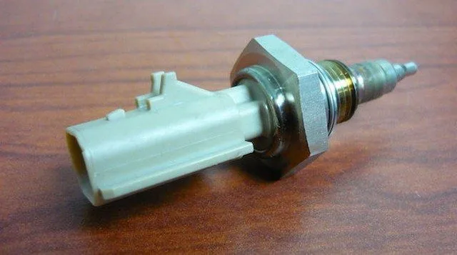
The EGR system allows some exhaust gases to be recycled, reducing pollution and improving combustion efficiency. The EGR temperature sensor plays a key role by enabling the engine control module (ECM) to monitor temperature and adjust the flow of recycled gases via the EGR valve.

When the ECM detects an erratic or intermittent signal from the EGR temperature sensor “A,” it logs the P040E code. The exact location of the sensor may vary by vehicle, so it is recommended to consult a specific repair manual.

Severity of the P040E Code

Although this code is generally not critical for driving, it can lead to increased pollutant emissions and affect engine performance. A malfunctioning EGR system can also cause exhaust leaks or overheating of certain components. Therefore, it is best to resolve the issue quickly to avoid long-term damage.

Symptoms of the P040E Code

A vehicle with this code may exhibit several symptoms:

  • Failure of emissions testing due to excessive emissions
  • Abnormal engine noises (knocking, pinging)
  • Louder than normal exhaust
  • Excessive exhaust gas odor

Possible Causes of the P040E Code

The P040E code can be caused by several factors:

  • Faulty or damaged EGR temperature sensor
  • Leaking EGR temperature sensor gasket
  • Crack or leak in the exhaust pipe where the sensor is mounted
  • Damaged wiring harness (melted, cut, short circuit)
  • Faulty or improperly connected electrical connector
  • Issue with the engine control module (ECM)

Diagnostic and Repair Steps

1. Visual Inspection of the EGR System

Start by examining the sensor and surrounding components for exhaust leaks, burnt wires, or loose connections. A buildup of black soot around the sensor may indicate a leak.

2. Cleaning the Sensor and EGR System

Clogging of the EGR system is a common cause of malfunction. Clean the sensor and EGR circuit with carburetor cleaner and a wire brush. If the sensor is difficult to remove, apply moderate heat (such as from a heat lamp) to loosen it. When reassembling, use anti-seize compound on the threads to facilitate future maintenance.

Warning: Forcible removal may break the sensor inside the exhaust manifold, leading to costly repairs.

3. Checking the Sensor’s Electrical Values

Use a multimeter to measure the sensor’s electrical values and compare them to the manufacturer’s specifications. A significant deviation indicates a faulty sensor or wiring issue.

Conclusion

Although the P040E code is not a critical failure, it is essential to resolve it quickly to avoid increased pollutant emissions and degraded engine performance. A thorough inspection and preventive maintenance of the EGR system can help avoid costly long-term repairs.

P040F EGR Temperature Sensor A/B Correlation

What does it mean?

This diagnostic trouble code (DTC) is a generic powertrain code, meaning it applies to OBD-II equipped vehicles (Ford, Seat, Chevy, GMC, Ford, Dodge, Sprinter, VW, Subaru, etc.). Although generic, specific repair steps may vary by make/model.

If your OBD-II equipped vehicle has stored a P040F code, it means the powertrain control module (PCM) has detected a discrepancy between the primary and secondary exhaust gas recirculation (EGR) temperature sensors (A and B). A stored P040F code can result from a mechanical issue or an electrical malfunction.

The EGR system is designed to return some of the spent exhaust gases to the intake manifold so they can be burned a second time. This process is necessary to reduce nitrogen oxide (NOx) particles released into the atmosphere. NOx is a component contributing to ozone-depleting exhaust emissions, and NOx emissions are regulated by federal mandate.

EGR temperature sensors are (to my knowledge) relegated to diesel engine vehicles. In most cases, engine coolant is used to lower the temperature of the engine exhaust gases before they are drawn into the EGR valve. The EGR temperature sensors A and B provide the PCM with variations in exhaust gas temperature near the EGR valve. The PCM compares the input signals from both EGR temperature sensors and an exhaust temperature sensor to determine if the EGR cooling system is functioning effectively.

EGR temperature sensors are located near the EGR valve, and the exhaust temperature sensor is typically positioned in the downpipe. If the input voltage signals from the EGR temperature sensor do not meet programmed specifications, or if the input signals from the EGR temperature sensor(s) are not significantly lower than those from the exhaust temperature sensor, a P040F will be stored, and a malfunction indicator lamp may illuminate.

Other EGR temperature sensor fault codes include P040A, P040B, P040C, P040D, P041A, P041B, P041C, P041D, P041E, and P041F.

Code Severity and Symptoms

Since P040F is related to the exhaust gas recirculation system, it is not classified as a severe code.

Symptoms of this code may include:

  • There may be no symptoms when this code is stored
  • Reduced fuel efficiency
  • Coolant leak
  • Exhaust leak
  • Exhaust temperature sensor codes

Causes

Possible causes for setting this code are as follows:

  • Low coolant
  • Faulty EGR temperature sensor(s)
  • Faulty exhaust temperature sensor
  • Exhaust leaks
  • Clogged EGR cooler
  • Engine overheating

Diagnostic and Repair Procedures

A diagnostic scanner, digital volt/ohmmeter, reliable vehicle information source (All Data DIY), and an infrared thermometer (with laser pointer) are some tools I would use to diagnose a P040F.

You can start with a visual inspection of the wiring harnesses and connectors associated with the EGR temperature sensors A and B and the exhaust temperature sensor. Carefully examine harnesses near hot exhaust pipes and manifolds.

Next, connect the scanner to the vehicle’s diagnostic connector and retrieve all stored codes and freeze frame data. Note this information as you might need it if it turns out to be an intermittent code. Now, clear the codes and test-drive the vehicle to see if it resets.

If P040F resets, I would use the scanner’s data stream to determine if there is an actual correlation problem between the two EGR temperature sensors or if there is a PCM or programming error. By narrowing the scanner’s data stream to include only relevant information, you can get a faster and more accurate data response. If the scanner indicates that actual temperature inputs meet specifications, suspect a faulty PCM or PCM programming error.

If EGR temperature sensor data is erratic or does not match desired parameters, test the sensors following manufacturer recommendations. Replace sensors that do not meet manufacturer specifications. If sensors function correctly, begin testing EGR temperature sensor circuits. Ensure all associated controllers are disconnected before testing with the DVOM. Repair or replace open or shorted circuits as needed.

If EGR temperature sensor electrical systems are functioning normally, use the infrared thermometer to check exhaust gas temperature at the EGR cooler inlet and EGR cooler outlet (with the engine running at normal operating temperature). Compare your results with manufacturer specifications and replace faulty EGR cooling system components if necessary.

Additional Diagnostic Notes:

  • Aftermarket mufflers and other exhaust components can cause exhaust temperature variations that might trigger this code
  • Exhaust backpressure issues, created by an inadequate diesel particulate filter (DPF), are known to contribute to P040F code storage conditions
  • Diagnose and repair DPF-related codes before attempting to diagnose this code
  • If the EGR system has been modified using an EGR blocking kit (currently offered by OEMs and aftermarket companies), this type of code may be stored

P0410 Secondary Air Injection System Malfunction

What does it mean?

This diagnostic code (DTC) is a generic powertrain code, meaning it applies to vehicles equipped with OBD-II. Although generic, specific repair steps may vary by make/model.

The P0410 code refers to the emissions system. The AIR pump puts air into the exhaust to reduce emissions. It draws in outside air and pumps it through two one-way check valves into each exhaust row.

About 90% of the time this code is set, the one-way check valves are worn or faulty and allow water (which occurs naturally in the exhaust) to flow back into the pump. In any cold climate, especially in climates with higher humidity, this water can be more excessive. The water partially fills the AIR pump, which can then freeze. When the PCM commands the pump, if the pump is frozen, it cannot turn, thus overloading the circuit and “blowing” the fuse.

Other secondary air injection system fault codes include P0411, P0412, P0413, P0414, P0415, P0416, P0417, P0418, P0419, P041F, P044F, P0491, and P0492.

Symptoms

Symptoms may include:

MIL illumination obviously
Hesitation on acceleration
Noise from a faulty/stuck air pump

Causes

A P0410 code can mean that one or more of the following events have occurred:

Water may have accumulated in the AIR pump or vent solenoid and frozen or corroded the pump
Air pump fuse blown due to freezing

Possible Solutions

Note: There is a Technical Service Bulletin (TSB) regarding this code for a number of GM models. The TSB calls for replacing the AIR pump and installing a new secondary injection pipe. The TSB can be found on this ACDelco website.

Additionally, if you simply replace the AIR pump, the problem may recur (and again). If you replace the pump, also clean the pipes and replace the one-way check valve. If it is a GM model to which the TSB applies, follow the instructions in the link above. In some cases, people have put a small hole in the rubber cover of the pump to allow water to drain out.

Also please note that this may be covered by the vehicle’s emissions warranty. If your vehicle is no longer covered by the bumper-to-bumper warranty, check if the emissions warranty is still valid!

Replace the AIR pump AND the one-way check valve
Test and clean the air pump AND test and replace the one-way air check valve
Replace the AIR pump inlet pipe
Replace the AIR pump fuse (located under the hood)

P0411 Incorrect Flow of Secondary Air Injection System Detected

What does it mean?

This diagnostic trouble code (DTC) is a generic powertrain code, meaning it applies to vehicles equipped with OBD-II. Although generic, specific repair steps may vary by make/model.

Secondary air injection is an emissions control that uses an air pump (electric or driven by the drive belt) to move fresh air into the exhaust manifold(s) or exhaust ports when the engine is in open loop and the pre-catalytic converter when in closed loop. This reduces hydrocarbon (HC), carbon monoxide (CO), and nitrogen oxide (NOx) emissions. This fresh air helps convert carbon monoxide (CO) into carbon dioxide (CO2) and hydrocarbons (HC) into water vapor (H2O).

A check valve is located in the air supply line to prevent exhaust gases from entering the pump. A shutoff valve that controls airflow may be vacuum-operated or electrically controlled. When the powertrain control module (PCM) activates the valve, vacuum is sent to the shutoff valve to open it and allow fresh air to flow. Some systems may only have a check valve, and airflow may be regulated by an electromagnetic clutch on the air pump (similar to an A/C clutch).

During heavy acceleration, the air pump will be deactivated to prevent backfiring in the exhaust. For self-monitoring, the AIR system will be activated by the PCM, and fresh air will be routed to the exhaust system. The oxygen sensors would sense this fresh air as a lean condition, and short-term fuel trims would begin moving in the positive direction to compensate. The PCM expects this to happen within seconds during the self-test. If it does not see short-term fuel trims increase, the PCM interprets this as an AIR system malfunction, and a code will be recorded.

Other secondary air injection system fault codes include P0410, P0412, P0413, P0414, P0415, P0416, P0417, P0418, P0419, P041F, P044F, P0491, and P0492.

Symptoms

Symptoms of a DTC P0411 may include:

MIL (Malfunction Indicator Lamp) illumination
Backfiring in the exhaust under heavy acceleration
Engine running rich (counterintuitive; see explanation below)
Squealing belt

Causes

Potential causes of a P0411 code include:

Damaged or missing check valve
Clogged/damaged air pump intake orifice
Air pump clutch malfunction
Holes or damage to exhaust components

Possible Solutions

If you have access to a scan tool, with KOEO (Key On Engine Off), command the AIR pump. It should activate. If not, remove and inspect the AIR pump relay for any discoloration/melting due to heat. Repair as needed.

Key on (engine off), check battery voltage at the battery switched power supply to the relay and the relay control circuit. If neither is present, inspect the circuit for a blown fuse or open/short in the wiring. Repair the cause of the short and retest. If both are present, connect battery power to the AIR pump power supply circuit using a fused jumper. The pump should activate. If not, check for power and ground present at the AIR pump when plugged in. If there is no voltage/ground at the pump, open the wiring harness. If voltage and ground are present, but the pump still does not operate, suspect a faulty AIR pump. If after jumping the AIR pump power supply circuit the pump activates, then the issue is likely the AIR pump relay. Replace and retest.

If the scan tool activates the AIR pump, with KOER (Key On Engine Running), activate the AIR pump solenoid valve and see if there is vacuum at the shutoff valve. There must be vacuum to open the valve. If there is no vacuum, check the AIR pump vacuum solenoid for manifold vacuum supply. If vacuum is present, the vacuum solenoid is likely faulty. Replace. If no vacuum is present at the vacuum solenoid supply, look for a clogged or damaged vacuum line or vacuum orifice. But if there is vacuum at the shutoff valve, stop the engine and using a vacuum pump, apply vacuum to the shutoff valve and see if it holds vacuum and if air flows through it when vacuum is applied. If it does not hold vacuum or the valve does not flow when vacuum is applied, replace the shutoff valve. If the shutoff valve operates correctly, inspect the check valve to see if it is clogged or missing. Replace as needed.

Check the exhaust catalyst steel line as well as the exhaust orifices for damage or holes that could cause false readings.

P0412 Malfunction in Circuit A of the Secondary Air Injection System Switching Valve

What does it mean?

This diagnostic trouble code (DTC) is a generic powertrain code, meaning it applies to vehicles equipped with OBD-II. Although generic, specific repair steps may vary by make/model.

The secondary air injection (AIR) system switching valve is the computer-controlled valve that controls air injection into the engine’s exhaust system (this valve may be integral to the AIR pump). This code deals with an issue in the SOLENOID circuit, not the operation of the AIR pump itself.

The AIR injection system reduces hydrocarbon (HC), carbon monoxide (CO), and nitrogen oxide (NOx) emissions by injecting fresh air into the exhaust ports of a cold engine or the catalytic converter of a hot engine. This helps convert hydrocarbons into water vapor (H₂O) and carbon monoxide into carbon dioxide (CO₂).

Generally, the electric air pump is the most common type, though there may be belt-driven air pumps with an electric clutch. The electric air pump is controlled by the PCM (powertrain control module), which grounds the AIR pump relay control circuit and provides voltage to the AIR pump and solenoid valve (which may control a vacuum-operated shut-off valve or directly control airflow). There is a check valve in the fresh air supply tube that prevents exhaust gases from flowing back into the AIR pump.

The PCM monitors the driver that activates the AIR pump for faults. When the PCM commands the AIR pump relay on, the control circuit voltage is naturally pulled near zero. When the relay is commanded off, the control circuit should have battery voltage present. If the PCM detects a voltage that is not as expected, P0412 will be set.

Other secondary air injection system fault codes include P0410, P0411, P0413, P0414, P0415, P0416, P0417, P0418, P0419, P041F, P044F, P0491, and P0492.

Symptoms

Symptoms of a P0412 DTC may include:

• MIL (Malfunction Indicator Lamp) illuminated
• Increased exhaust emissions
• Rich running engine

Causes

Potential causes of a P0412 code include:

• Short to ground in the control circuit
• Short to voltage in the control circuit
• Open control circuit due to damage, etc.
• Open or short in the battery supply circuit to the solenoid
• Open or short in the battery supply to the relay control circuit

Possible Solutions

If you have access to a scan tool, with KOEO (Key On Engine Off), activate and deactivate the AIR pump solenoid. If the solenoid does not operate, disconnect the solenoid and use a voltmeter to check that voltage is supplied to the solenoid when commanded and also for a good ground. If there is voltage supplied and a good ground, check for a proper connection at the solenoid wiring harness connector. If the connection is good, replace the solenoid. If there is no voltage supplied to the connector when commanding the solenoid, locate the AIR pump relay and check for fused battery voltage on the switched side of the circuit that powers the AIR pump; if not, check for a blown fuse or open in the wiring. Repair and retest.

If battery voltage is present on the voltage supply side of the relay, a quick way to check proper solenoid and AIR pump operation is to use a fused jumper and manually activate it. To do this, connect battery voltage to the switched voltage supply of the AIR pump. This is typically terminals 30 and 87 in the relay diagram (not always). If the solenoid (and possibly the AIR pump) operates, then you know your wiring and solenoid are correct. If it does not activate, open the wiring harness and find the open or short in the AIR pump solenoid supply and fix it. If connecting the solenoid to battery voltage activates the solenoid, it’s time to check for voltage present with KOEO on the PCM-controlled side of the relay. If there is none, again repair the open or short in the circuit and retest.

To check the AIR pump solenoid PCM wiring, grounding the control circuit, which is normally operated by the PCM, will tell you if the wiring is intact. Grounding the circuit at the PCM connector with KOEO should activate the AIR pump relay, which in turn should activate the AIR pump and solenoid. If this does not work, there is an open or short in the PCM control circuit. If grounding the control circuit makes the AIR pump and solenoid operate, check that the PCM has good ground paths and no connector damage or water intrusion. If this checks out, suspect an open driver in the PCM.

P0413 Secondary Air Injection System A Open

What does it mean?

This diagnostic code (DTC) is a generic powertrain code, meaning it applies to vehicles equipped with OBD-II (Dodge, Ram, Ford, GMC, Chevrolet, VW, Toyota, etc.). Although generic, specific repair steps may vary by make/model.

When diagnosing a P0413 code, it means the Powertrain Control Module (PCM) has detected a malfunction in a switching valve circuit of the Secondary Air Injection (SAI) system. This particular switching valve is designated as A. The A designates a specific switching valve in a system that uses multiple switching valves, or the only valve if there is only one switching valve.

In diagnostic terms, the word “open” could be substituted for disconnected, broken, or severed. Consult a reliable vehicle information source to determine the SAI switching valve circuit configuration for the vehicle in question and the exact location of switching valve A. To reduce harmful exhaust emissions, the SAI system pumps ambient air into the engine’s exhaust system. Most automotive SAI systems use a belt-driven pump to draw in ambient air, slightly compress it, and inject the pressurized air into the engine’s exhaust manifolds.

One-way valves, switching valves, check valves, and bypass valves, controlled by the PCM, are used to regulate and distribute air pressure as well as protect the SAI pump. The PCM receives voltage input signals from strategically placed pressure sensors to monitor SAI system pressure fluctuations. When the required parameters are met, the PCM electronically opens the necessary valves and allows secondary air to be pumped into the exhaust system.

Some vehicles are equipped with SAI systems designed with an electric pump. In this type of system, the PCM monitors pressure sensors and activates the pump if necessary.

If the PCM detects a voltage input signal from the SAI switching valve (designated A) that is too low or non-existent, a P0413 code will be stored and a malfunction indicator light may be illuminated.

Other secondary air injection system fault codes include P0410, P0411, P0412, P0414, P0415, P0416, P0417, P0418, P0419, P041F, P044F, P0491, and P0492.

Code Severity and Symptoms

The SAI system is only related to reducing exhaust emissions and is not essential to engine operation. A stored P0413 code should not be considered severe.

Symptoms of this code may include:

  • There are probably no symptoms associated with this code
  • A hissing or choking noise from the pipes or SAI pump is possible
  • Loud whining from the SAI pump

Causes

Possible causes for this code being set are:

  • Burned or broken wiring and/or connectors in the SAI system
  • Frozen SAI pump (in extremely cold climate geographical areas)
  • Faulty SAI pump
  • Faulty SAI pump relay
  • Bad SAI pressure sensor

Diagnostic and Repair Procedures

A diagnostic scanner, a digital volt/ohmmeter (DVOM), and a reliable source of vehicle information will be needed to diagnose a P0413 code.

I would begin my diagnosis by inspecting the system’s wiring and connectors and the serpentine belt that drives the pump (if applicable). Repair or replace open circuits as needed and retest the system. If the pump is belt-driven and the belt is missing or otherwise defective, replace it before continuing. Ensure the pump spins freely by hand before replacing the belt. Pump failure is relatively common in high-mileage vehicles. If the SAI pump is driven by an electric motor, I also like to check the system fuses and relays at this point.

If a visual inspection does not lead to any obvious malfunction, connect the scanner to the vehicle’s diagnostic port and retrieve all stored codes and freeze frame data. This information can be useful in my diagnosis, so I like to write it down. Now, clear the codes and test-drive the vehicle to see if the P0413 resets.

Consult your vehicle information source to search Technical Service Bulletins (TSBs) for entries matching the code(s) and symptom(s) presented by the vehicle in question. Since TSBs are compiled using data from hundreds of thousands of repairs, the information they contain can be very helpful in reaching a successful diagnosis.

In extremely cold weather conditions, belt-driven SAI pumps are prone to seizing due to frozen condensation. Typically, a one-way check valve is built into the air supply pipe to prevent condensation from reaching the SAI pump. One-way check valves regularly fail and allow exhaust condensation to enter the SAI pump. Once the condensation freezes, the ice seizes the (belt-driven) SAI pump or causes it to bind and blow a fuse (electric pump).

Use the scanner to activate the electric SAI pump. Once the pump is activated, use the DVOM to test for voltage and ground at the SAI pump. If no voltage is detected, suspect a blown fuse or a faulty power relay. If all fuses and relays are good, use the DVOM to check for an open circuit between the power source and the pump. Disconnect all associated controllers before using the DVOM to check circuit resistance. If no ground is detected, use your vehicle information source to locate the proper ground source and test for voltage drop in the circuit.

Test the SAI pressure sensor using the DVOM and the specifications located in your chosen vehicle information source.

Additional diagnostic notes:

  • Blown fuses are usually a reaction to a short circuit and not the source of the malfunction
  • Frozen pumps may be thawed before use to avoid catastrophic damage to the pump

P0414 Secondary Air Injection System Shorted

What does it mean?

This diagnostic trouble code (DTC) is a generic powertrain code, meaning it applies to OBD-II equipped vehicles (Dodge, Ram, Ford, GMC, Chevrolet, VW, Toyota, etc.). Although generic, the specific repair steps may vary by make/model.

A stored code P0414 simply means that the Powertrain Control Module (PCM) has detected a short circuit in a Secondary Air Injection (SAI) system switching valve circuit. This particular switching valve is designated A and refers to a specific switching valve in a system that uses multiple switching valves, or the sole valve if a single-valve system exists. A short circuit could mean the affected circuit came into contact with an unexpected voltage signal or ground. A short circuit will typically result in a blown fuse.

The SAI system pumps ambient air into the engine’s exhaust system as a method of reducing harmful exhaust emissions. Automotive SAI systems use a belt-driven pump or an electric pump to draw in ambient air, compress it slightly, and inject the pressurized air into the engine’s exhaust manifolds. One-way valves, switching valves, check valves, and bypass valves (controlled by the PCM) are used to regulate and distribute air pressure and protect the SAI air pump.

The PCM receives voltage input signals from pressure sensors to monitor SAI system pressure fluctuations. When appropriate conditions are met, the PCM electronically opens the necessary valves and allows secondary air to be pumped into the exhaust system. The PCM monitors the SAI pressure sensors and activates the pump if necessary in vehicles equipped with electric pumps.

If the PCM detects a voltage input signal from the SAI switching valve circuit (designated as A) that indicates a short circuit (to voltage or to ground), a P0414 code will be stored and a malfunction indicator lamp may be illuminated.

Other secondary air injection system fault codes include P0410, P0411, P0412, P0413, P0415, P0416, P0417, P0418, P0419, P041F, P044F, P0491, and P0492.

Code Severity and Symptoms

A stored P0414 code should not be considered severe. The SAI system is only related to reducing exhaust emissions and is not essential to engine operation. However, if the SAI circuit is shorted to voltage, constant activation of the pump may lead to battery drain.

Symptoms of this code may include:

Constant SAI pump activation (short to voltage)
No SAI pump activation (short to ground with a blown fuse)
Loud whining from the SAI pump

Causes

Causes

Possible causes for setting this code are as follows:

Short-circuited wiring, components, and/or connectors in the SAI system
Short-circuited SAI pump

Diagnostic and Repair Procedures

A diagnostic scanner, a digital volt/ohmmeter (DVOM), and a reliable vehicle information source (such as All Data DIY) will be needed to properly diagnose a P0414 code.

Inspecting the system wiring, connectors, and the serpentine belt driving the pump (if applicable) is a good place to start your diagnosis. Repair or replace shorted circuits as needed and retest the system. If the belt is missing or otherwise defective (belt-driven pump), replace it before continuing. Ensure the pump spins freely by hand before replacing the belt. I like to check the system fuses and relays at this point if the SAI pump is driven by an electric motor.

Continue by connecting the scanner to the vehicle’s diagnostic port and retrieving all stored codes and freeze frame data, if your visual inspection leads to no obvious malfunction. I like to note this information as it may prove helpful later in my diagnosis. Then, I clear the codes and test drive the vehicle to see if the P0414 resets.

Search for Technical Service Bulletins (TSBs) using your vehicle information source to find entries that match the code(s) and symptom(s) presented by the vehicle in question. TSBs consist of hundreds of thousands of repairs and the information contained within can be very helpful in arriving at a successful diagnosis. Belt-driven SAI pumps are prone to seizing (due to frozen condensation) in extremely cold weather conditions. A one-way check valve is normally integrated into the air supply hose to prevent condensation from reaching the SAI pump. One-way check valves can fail and allow exhaust condensation to enter the SAI pump. The condensation freezes and the ice can cause the SAI pump (belt-driven) to seize or cause it to lock up and blow a fuse (electric pump).

Proceed by using the scanner to activate the electric SAI pump. Once the pump is activated, you can use the DVOM to test for voltage and ground at the SAI pump. Suspect a blown fuse or a faulty power relay if no voltage is detected. Use the DVOM to check for an open circuit between the power source and the pump if all fuses and relays are in good condition. Before using the DVOM to check circuit resistance, disconnect all associated controllers.

Test the individual system circuits for shorts to ground or voltage using the DVOM and a wiring diagram from your vehicle information source. Repair or replace circuits that show unexpected ground or voltage signals.

Additional diagnostic notes:

* Blown fuses are typically a reaction to a short circuit and not the source of the malfunction
* Frozen pumps may thaw before use to avoid catastrophic damage to the pump

P0415 Secondary Air Injection System Switching Valve B Circuit Malfunction

What does it mean?

This diagnostic trouble code (DTC) is a generic powertrain code, meaning it applies to vehicles equipped with OBD-II. Although generic, specific repair steps may vary by make/model.

The secondary air injection (AIR) system switching valve is the computer-controlled valve that controls air injection into the engine’s exhaust system (this valve may be integral to the AIR pump). This code deals with an issue in the SOLENOID circuit, not the operation of the AIR pump itself.

The AIR injection system reduces hydrocarbon (HC), carbon monoxide (CO), and nitrogen oxide (NOx) emissions by injecting fresh air into the exhaust ports of a cold engine or the catalytic converter of a hot engine. This helps convert hydrocarbons into water vapor (H₂O) and carbon monoxide into carbon dioxide (CO₂).

Typically, the electric air pump is the most common type, though there may be belt-driven air pumps with an electric clutch. The electric air pump is controlled by the PCM (powertrain control module), which grounds the AIR pump relay control circuit and provides voltage to the AIR pump and solenoid valve (which may control a vacuum-operated shutoff valve or directly control airflow). There is a check valve in the fresh air supply tube that prevents exhaust gases from flowing back into the AIR pump.

The PCM monitors the driver that activates the AIR pump for faults. When the PCM commands the AIR pump relay on, the control circuit voltage is naturally pulled near zero. When the relay is commanded off, the control circuit B should have battery voltage present. If the PCM detects a voltage that is not as expected, P0415 will be set.

Other secondary air injection system fault codes include P0410, P0411, P0412, P0413, P0414, P0416, P0417, P0418, P0419, P041F, P044F, P0491, and P0492.

Symptoms

Symptoms of a P0415 DTC may include:

  • MIL (Malfunction Indicator Lamp) illumination
  • Increased exhaust emissions
  • Rich running engine

Causes

Potential causes of a P0415 code include:

  • Short to ground in control circuit B
  • Short to voltage in control circuit B
  • Open control circuit due to damage, etc.
  • Open or short in battery supply circuit to solenoid
  • Open or short in battery supply to relay control circuit

Possible Solutions

If you have access to a scan tool, with KOEO (Key On Engine Off), activate and deactivate the AIR pump solenoid. If the solenoid does not operate, disconnect the solenoid and using a voltmeter, verify that voltage is supplied to the solenoid when commanded and also for a good ground. If there is voltage supplied and a good ground, check for a good connection at the solenoid wiring harness connector. If the connection is good, replace the solenoid. If there is no voltage supplied to the connector when commanding the solenoid, locate the AIR pump relay and verify there is fused battery voltage on the switched side of the circuit that powers the AIR pump; if not, check for a blown fuse or open in the wiring. Repair and retest.

If battery voltage is present on the voltage supply side of the relay, a quick way to check proper solenoid and AIR pump operation is to use a fused jumper and manually activate it. To do this, connect battery voltage to the switched voltage supply of the AIR pump. This is typically terminals 30 and 87 on the relay diagram (not always). If the solenoid (and possibly the AIR pump) operates, then you know your wiring and solenoid are correct. If it does not activate, open the wiring harness and find the open or shorted circuit in the AIR pump solenoid supply and fix it. If connecting the solenoid to battery voltage activates the solenoid, it’s time to check for voltage present with KOEO on the PCM-controlled side of the relay. If there is none, again repair open or shorted in the circuit and retest.

To check the AIR pump solenoid PCM wiring, grounding the control circuit that is normally operated by the PCM will tell you if the wiring is intact. Grounding the circuit at the PCM connector with KOEO should activate the AIR pump relay, which in turn should activate the AIR pump and solenoid. If this does not work, there is an open or short in the PCM control circuit. If grounding the control circuit makes the AIR pump and solenoid operate, check that the PCM has good ground paths and no connector damage or water intrusion. If this checks out, suspect an open driver in the PCM.

P0416 Open Secondary Air Injection System

P0416 Secondary Air Injection System Open

What Does It Mean?

This diagnostic code (DTC) is a generic powertrain code, meaning it applies to vehicles equipped with OBD-II (Dodge, Ram, Ford, GMC, Chevrolet, VW, Toyota, etc.). Although generic, specific repair steps may vary by make/model.

When faced with diagnosing a P0416 code, it means the Powertrain Control Module (PCM) has detected a malfunction in a switching valve circuit of the Secondary Air Injection (SAI) system. This particular switching valve is designated B. Typically, B refers to a specific switching valve in a system that uses multiple switching valves.

In diagnostic terms, the word “open” could be substituted for disconnected, broken, or cut. Consult a reliable vehicle information source to determine the SAI switching valve circuit configuration for the vehicle in question and the exact location of switching valve B. To reduce harmful exhaust emissions, the SAI system pumps ambient air into the engine’s exhaust system. Most automotive SAI systems use a belt-driven pump to draw in ambient air, compress it slightly, and inject the pressurized air into the engine’s exhaust manifolds.

One-way valves, switching valves, check valves, and bypass valves, controlled by the PCM, are used to regulate and distribute air pressure as well as protect the SAI pump. The PCM receives voltage input signals from strategically placed pressure sensors to monitor SAI system pressure fluctuations. When the required parameters are met, the PCM electronically opens the necessary valves and allows secondary air to be pumped into the exhaust system.

Some vehicles are equipped with SAI systems designed with an electric pump. In this type of system, the PCM monitors pressure sensors and activates the pump if necessary.

If the PCM detects a voltage input signal from the SAI switching valve (designated B) that is too low or non-existent, a P0416 code will be stored and a Malfunction Indicator Lamp may be illuminated.

Other secondary air injection system fault codes include P0410, P0411, P0412, P0413, P0414, P0415, P0417, P0418, P0419, P041F, P044F, P0491, and P0492.

Code Severity and Symptoms

The SAI system is only related to reducing exhaust emissions and is not essential to engine operation. A stored P0416 code should not be considered severe.

Symptoms of this code may include:

  • There are probably no symptoms associated with this code
  • A hissing or choking noise from the pipes or SAI pump is possible
  • Loud whining from the SAI pump

Possible causes for setting this code are:

  • Burned or broken wiring and/or connectors in the SAI system
  • Frozen SAI pump (in extremely cold climate geographical areas)
  • Faulty SAI pump
  • Faulty SAI pump relay
  • Bad SAI pressure sensor

Diagnostic and Repair Procedures

A diagnostic scanner, a digital volt/ohmmeter (DVOM), and a reliable source of vehicle information will be needed to diagnose a P0416 code.

I would start my diagnosis by inspecting the system’s wiring and connectors and the serpentine belt that drives the pump (if applicable). Repair or replace open circuits as needed and retest the system. If the pump is belt-driven and the belt is missing or otherwise defective, replace it before continuing. Ensure the pump spins freely by hand before replacing the belt. Pump failure is relatively common in high-mileage vehicles. If the SAI pump is driven by an electric motor, I also like to check the system’s fuses and relays at this time.

If a visual inspection leads to no obvious malfunction, connect the scanner to the vehicle’s diagnostic port and retrieve all stored codes and freeze frame data. This information can be useful in my diagnosis, so I like to write it down. Now, clear the codes and test-drive the vehicle to see if the P0416 resets.

Consult your vehicle information source to search Technical Service Bulletins (TSBs) for entries matching the code(s) and symptom(s) presented by the vehicle in question. Since TSBs are compiled using data from hundreds of thousands of repairs, the information they contain can be very helpful in reaching a successful diagnosis.

In extremely cold weather conditions, belt-driven SAI pumps are prone to seizing due to frozen condensation. Typically, a one-way check valve is built into the air supply hose to prevent condensation from reaching the SAI pump. One-way check valves regularly fail and allow exhaust condensation to enter the SAI pump. Once the condensation freezes, the ice seizes the (belt-driven) SAI pump or causes it to bind and blow a fuse (electric pump).

Use the scanner to activate the electric SAI pump. Once the pump is activated, use the DVOM to test for voltage and ground at the SAI pump. If no voltage is detected, suspect a blown fuse or a faulty power relay. If all fuses and relays are in good condition, use the DVOM to look for an open circuit between the power source and the pump. Disconnect all associated controllers before using the DVOM to check circuit resistance. If no ground is detected, use your vehicle information source to locate the proper ground source and test for voltage drop in the circuit.

Test the SAI pressure sensor using the DVOM and the specifications located in your chosen vehicle information source.

Additional Diagnostic Notes:

*Blown fuses are usually a reaction to a short circuit and not the source of the malfunction
* Frozen pumps can be thawed before use to avoid catastrophic damage to the pump

P0417 Secondary Air Injection System B Shorted

What does it mean?

This diagnostic trouble code (DTC) is a generic powertrain code, meaning it applies to OBD-II equipped vehicles (Dodge, Ram, Ford, GMC, Chevrolet, VW, Toyota, etc.). Although generic, specific repair steps may vary by make/model.

A stored P0417 code simply means the powertrain control module (PCM) has detected a short circuit in a secondary air injection (SAI) system switching valve circuit. This particular switching valve is designated B and refers to a specific switching valve in a system that uses multiple switching valves. A short circuit could mean the affected circuit has come into contact with an unexpected voltage signal or ground. A short circuit will typically result in a blown fuse.

The SAI system pumps ambient air into the engine’s exhaust system as a method of reducing harmful exhaust emissions. Automotive SAI systems use a belt-driven pump or an electric pump to draw in ambient air, slightly compress it, and inject the pressurized air into the engine’s exhaust manifolds. One-way valves, switching valves, check valves, and bypass valves (controlled by the PCM) are used to regulate and distribute air pressure and protect the SAI air pump.

The PCM receives voltage input signals from pressure sensors to monitor SAI system pressure fluctuations. When appropriate conditions are met, the PCM electronically opens the necessary valves and allows secondary air to be pumped into the exhaust system. The PCM monitors SAI pressure sensors and activates the pump if necessary in vehicles equipped with electric pumps.

If the PCM detects a voltage input signal from the SAI switching valve circuit (designated B) that indicates a short circuit (to voltage or to ground), a P0417 code will be stored and a malfunction indicator lamp may be illuminated.

Other secondary air injection system fault codes include P0410, P0411, P0412, P0413, P0414, P0415, P0416, P0418, P0419, P041F, P044F, P0491, and P0492.

Code Severity and Symptoms

A stored P0417 code should not be considered severe. The SAI system is only related to reducing exhaust emissions and is not essential to engine operation. However, if the SAI circuit is shorted to voltage, constant pump activation may lead to battery drain.

Symptoms of this code may include:

Constant SAI pump activation (short to voltage)
No SAI pump activation (short to ground with a blown fuse)
Loud whining from the SAI pump

Causes

Possible causes for this code being set are:

Short-circuited wiring, components, and/or connectors in the SAI system
Short-circuited SAI pump

Diagnostic and Repair Procedures

A diagnostic scanner, a digital volt/ohmmeter (DVOM), and a reliable source of vehicle information (such as All Data DIY) will be needed to properly diagnose a P0417 code.

Inspecting the system wiring, connectors, and the serpentine belt that drives the pump (if applicable) is a good place to start your diagnosis. Repair or replace shorted circuits as needed and retest the system. If the belt is missing or otherwise defective (belt-driven pump), replace it before continuing. Ensure the pump spins freely by hand before replacing the belt. I like to check the system fuses and relays at this point if the SAI pump is driven by an electric motor.

Continue by connecting the scanner to the vehicle’s diagnostic port and retrieving all stored codes and freeze frame data, if your visual inspection leads to no obvious malfunction. I like to note this information as it may prove helpful later in my diagnosis. Then, I clear the codes and test drive the vehicle to see if the P0417 resets.

Search for technical service bulletins (TSBs) using your vehicle information source to find entries that match the code(s) and symptom(s) presented by the vehicle in question. TSBs consist of hundreds of thousands of repairs and the information contained within can be very helpful in arriving at a successful diagnosis. Belt-driven SAI pumps are susceptible to seizing (due to frozen condensation) in extremely cold weather conditions. A one-way check valve is normally integrated into the air supply pipe to prevent condensation from reaching the SAI pump. One-way check valves can fail and allow exhaust condensation to enter the SAI pump. The condensation freezes and the ice can cause the SAI pump (belt-driven) to seize or cause it to lock up and blow a fuse (electric pump).

Proceed by using the scanner to actuate the electric SAI pump. Once the pump is activated, you can use the DVOM to test for voltage and ground at the SAI pump. Suspect a blown fuse or a faulty power relay if no voltage is detected. Use the DVOM to check for an open circuit between the power source and the pump if all fuses and relays are in good condition. Before using the DVOM to check circuit resistance, disconnect all associated controllers.

Test individual system circuits for shorts to ground or voltage using the DVOM and a wiring diagram from your vehicle information source. Repair or replace circuits that show unexpected ground or voltage signals.

Additional diagnostic notes:

Blown fuses are typically a reaction to a short circuit and not the source of the malfunction
Frozen pumps may thaw before use to avoid catastrophic damage to the pump