P06B7 Internal Control Module Knock Sensor Processor 2 Performance

What does it mean?

This generic powertrain diagnostic trouble code (DTC) generally applies to many OBD-II vehicles. This may include, but is not limited to, vehicles from Chevrolet, Subaru, Ford, Mazda, BMW, Peugeot, etc.

When a P06B7 code is stored, it means the Powertrain Control Module (PCM) has detected an internal processor performance error with a specific knock sensor circuit (designated 2). Other controllers may also detect an internal PCM performance error (with the knock sensor circuit) and cause a P06B7 to be stored.

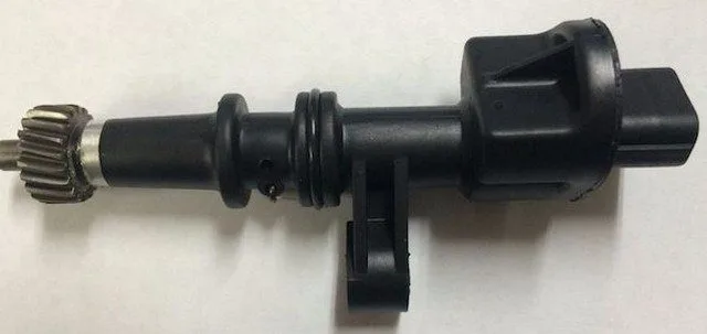
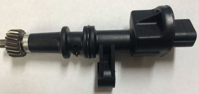
The knock sensor is typically screwed directly into the engine block. It is a piezoelectric sensor. The location of the knock sensor varies by manufacturer, but most are found on the sides of the block (between the cylinder liner coolant freeze plugs) or in the valley beneath the intake manifold. Knock sensors located on the sides of the engine block are often screwed directly into the engine’s coolant passages. When the engine is hot and the engine cooling system is pressurized, removing these sensors can result in severe burns from hot coolant. Before removing any knock sensor, allow the engine to cool and always dispose of coolant properly.

A piezoelectric sensing crystal is at the heart of the knock sensor. When shaken or vibrated, the piezoelectric crystal produces a small amount of voltage. Since the knock sensor control circuit is normally a one-wire circuit, the voltage generated by vibration is recognized by the PCM as engine noise or vibration. The severity of the vibration encountered by the piezoelectric crystal (inside the knock sensor) determines the level of voltage produced in the circuit.

If the PCM detects a degree of voltage from the knock sensor indicating engine knock or severe spark detonation; it may retard the ignition timing and a knock sensor control code may be stored.

A very small voltage is always produced by the knock sensor when the engine is running. This is because slight vibration is inevitable, no matter how smoothly the engine runs.

The internal control module monitoring processors are responsible for various controller self-test tasks and the overall responsibility of the internal control module. The knock sensor input and output signals are self-tested and are constantly monitored by the PCM and other associated controllers. The Transmission Control Module (TCM), the Traction Control System Module (TCSM), and other controllers also interact with the knock sensor system.

Whenever the ignition is turned on and the PCM is powered up, self-tests of the knock sensor system are initiated. In addition to performing internal controller self-tests, the Controller Area Network (CAN) also compares the signals from each individual module to ensure each controller is functioning correctly. These tests are performed simultaneously.

If the PCM detects an internal anomaly in the knock sensor processor, a P06B7 code will be stored and a Malfunction Indicator Lamp (MIL) may be illuminated. Additionally, if the PCM detects a problem between any of the onboard controllers, which would indicate an internal knock sensor system error, a P06B7 code will be stored and a Malfunction Indicator Lamp (MIL) may be illuminated. Multiple failure cycles may be required for MIL illumination, depending on the perceived severity of the malfunction.

How severe is this DTC?

Internal control module processor codes should be classified as severe. A stored P06B7 code could lead to various driving problems.
What are some of the symptoms of the code?

Symptoms of a P06B7 fault code may include:

  • Loud noises from the engine area
  • Reduced fuel efficiency
  • A variety of engine driving symptoms
  • Other stored diagnostic trouble codes

What are some of the common causes of the code?

Causes of this code may include:

  • Faulty PCM or PCM programming error
  • Faulty knock sensor
  • Faulty knock sensor control wiring and/or connectors
  • A faulty controller power relay or blown fuse
  • Open or shorted circuit or connectors in the CAN bus
  • Insufficient control module ground

What are the P06B7 troubleshooting steps?


Even for the most experienced and well-equipped professional technician, diagnosing a P06B7 code can be very challenging. There is also the issue of reprogramming. Without the necessary reprogramming equipment, it will be impossible to replace a faulty controller and perform a successful repair.

If ECM/PCM power codes are present, they will obviously need to be rectified before attempting to diagnose a P06B7.

There are several preliminary tests that can be performed before declaring a controller faulty. A diagnostic scanner, a digital volt/ohmmeter (DVOM), and a reliable source of vehicle information will be necessary.

Connect the scanner to the vehicle’s diagnostic port and retrieve all stored codes and freeze frame data. You will want to write this information down, just in case the code proves to be intermittent. After recording all relevant information, clear the codes and test drive the vehicle until the code resets or the PCM enters readiness mode. If the PCM enters readiness mode, the code is intermittent and will be more difficult to diagnose. The condition which caused the P06B7 to be stored may even need to worsen before a diagnosis can be made. If the code resets, continue with this short list of preliminary tests.

When trying to diagnose a P06B7, information can be your best tool. Search your vehicle information source for Technical Service Bulletins (TSBs) that match the stored code, the vehicle (year, make, model, and engine), and the symptoms presented. If you find the right TSB, it can provide diagnostic information that will help you significantly.

Use your vehicle information source to obtain connector face views, connector pinout diagrams, component locators, wiring schematics, and diagnostic flowcharts related to the specific code and vehicle in question.

Use the DVOM to test the controller power fuses and relays. Test and replace blown fuses as needed. Fuses should be tested under load.

If all fuses and relays appear to be working as expected, a visual inspection of the wiring and harnesses related to the controller is necessary. You will also want to check the chassis and engine ground connections. Use your vehicle information source to obtain ground locations for the related circuits. Use the DVOM to test ground integrity.

Visually inspect the system controllers for signs of water, heat, or collision damage. Any damaged controller, especially by water, should be considered faulty.

If the controller power and ground circuits are intact, suspect a faulty controller or a controller programming error. Replacing the controller will require reprogramming. In some cases, you can purchase pre-programmed controllers through aftermarket sources. Other vehicles/controllers will require onboard reprogramming that can only be performed by a dealer or other qualified source.

Unlike most other codes, P06B7 is likely caused by a faulty controller or a controller programming error
Test system ground integrity by connecting the DVOM negative test lead to ground and the positive test lead to battery voltage

Internal Control Module Non-Volatile Random-Access Memory (NVRAM) Error P06B8

What Does It Mean?


This generic powertrain diagnostic trouble code (DTC) generally applies to many OBD-II vehicles. This may include, but is not limited to, vehicles from Ford, Mazda, etc.

When a P06B8 code is stored, it means the Powertrain Control Module (PCM) has detected an internal processor performance error with non-volatile random access memory (NVRAM). Other controllers may also detect an internal PCM performance error (with NVRAM) and cause a P06B8 to be stored.

The internal control module monitoring processors are responsible for various controller self-test tasks and the overall responsibility of the internal control module. The NVRAM input and output signals are subjected to self-test and are continuously monitored by the PCM and other associated controllers. The Transmission Control Module (TCM), Traction Control System Module (TCSM), and other controllers also interact with the NVRAM.

In automotive applications, NVRAM is used to help retain data memory when the PCM is turned off. The NVRAM is integrated into the PCM. Even though NVRAM is capable of over a million programming changes and is designed to last for hundreds of years, it can be sensitive to excessive heat and humidity.

Whenever the ignition is turned on and the PCM is powered up, the NVRAM self-tests are initiated. In addition to running internal controller self-tests, the Controller Area Network (CAN) also compares the signals from each individual module to ensure each controller is functioning correctly. These tests are performed simultaneously.

If the PCM detects an internal anomaly in the NVRAM processor, a P06B8 code will be logged and a Malfunction Indicator Lamp (MIL) may be illuminated. Additionally, if the PCM detects a problem between any of the onboard controllers, which would indicate an internal knock sensor system error, a P06B8 code will be stored and a Malfunction Indicator Lamp (MIL) may be illuminated. Multiple failure cycles may be required for MIL illumination, depending on the perceived severity of the malfunction.

How Severe Is This DTC?


Internal control module processor codes should be classified as severe. A stored P06B8 code can lead to various driving issues.
What Are Some of the Symptoms of the Code?

Symptoms of a P06B8 trouble code may include:

A variety of engine driving symptoms
Other stored diagnostic trouble codes

What Are Some of the Common Causes of the Code?

Causes

of this code may include:

Faulty PCM or PCM programming error
Open or shorted circuit or connectors in the CAN harness
Insufficient control module ground

What Are the P06B8 Troubleshooting Steps?


Even for the most experienced and well-equipped professional technician, diagnosing a P06B8 code can prove very challenging. There is also the issue of reprogramming. Without the necessary reprogramming equipment, it will be impossible to replace a faulty controller and perform a successful repair.

If ECM/PCM power codes are present, they will obviously need to be corrected before attempting to diagnose a P06B8.

There are several preliminary tests that can be performed before declaring a controller faulty. A diagnostic scanner, a digital volt/ohmmeter (DVOM), and a reliable vehicle information source will be necessary.

Connect the scanner to the vehicle’s diagnostic port and retrieve all stored codes and freeze frame data. You will want to note this information, just in case the code proves to be intermittent. After recording all relevant information, clear the codes and test drive the vehicle until the code resets or the PCM enters readiness mode. If the PCM enters readiness mode, the code is intermittent and will be more difficult to diagnose. The condition that caused the P06B8 to be stored may even need to worsen before a diagnosis can be made. If the code resets, continue with this short list of preliminary tests.

When trying to diagnose a P06B8, information can be your best tool. Search your vehicle information source for Technical Service Bulletins (TSBs) that match the stored code, the vehicle (year, make, model, and engine), and the symptoms presented. If you find the right TSB, it may provide diagnostic information that will assist you significantly.

Use your vehicle information source to obtain connector face views, connector pinout diagrams, component locators, wiring schematics, and diagnostic flowcharts related to the code and vehicle in question.

Use the DVOM to test the controller’s power fuses and relays. Test and replace blown fuses as needed. Fuses should be tested with the circuit loaded.

If all fuses and relays appear to be functioning as expected, a visual inspection of the wiring and harnesses related to the controller is necessary. You will also want to check the chassis and engine ground junctions. Use your vehicle information source to obtain ground locations for the related circuits. Use the DVOM to test ground integrity.

Visually inspect the system controllers for signs of water, heat, or collision damage. Any damaged controller, especially by water, should be considered faulty.

If the controller’s power and ground circuits are intact, suspect a faulty controller or a controller programming error. Replacing the controller will require reprogramming. In some cases, you can purchase pre-programmed controllers through aftermarket sources. Other vehicles/controllers will require onboard reprogramming that can only be performed by a dealership or other qualified source.

Unlike most other codes, P06B8 is likely caused by a faulty controller or a controller programming error
Test the system ground integrity by connecting the DVOM’s negative test lead to ground and the positive test lead to battery voltage

P06B9 Cylinder 1 Glow Plug Circuit Range / Performance

What does it mean?


This is a generic diagnostic trouble code (DTC) for the powertrain and generally applies to OBD-II vehicles. This may include, but is not limited to, vehicles from Ford, Toyota, Dodge, Ram, Chevy, GMC, VW Audi, Peugeot, Citroen, etc. Although generic, the exact repair steps may vary depending on the year, make, model, and powertrain configuration.

When a P06B9 code is stored, it means that the Powertrain Control Module (PCM) has detected an anomaly in the glow plug control circuit for cylinder #1. Consult a reliable vehicle information source to determine the location of cylinder #1 for your specific year/make/model/powertrain configuration.

Diesel engines use high compression instead of spark to initiate piston movement. Since no spark is involved, the cylinder temperature must be increased to maximize compression. Glow plugs are used in each cylinder to achieve this temperature increase.

Often confused with spark plugs, a glow plug for each individual cylinder is screwed into the cylinder head. Battery voltage is applied to the glow plug element via a glow plug timer (sometimes called a glow plug controller or glow plug module) and/or the PCM. When voltage is properly applied to the glow plug, it will literally become red-hot and help raise the cylinder temperature. Once the cylinder temperature reaches the desired level, the voltage is limited by the control unit and the glow plug returns to its normal state.

If the PCM detects a voltage level in the glow plug control circuit for cylinder #1 that is outside the expected range, a P06B9 code will be stored and a Malfunction Indicator Lamp (MIL) may illuminate.

How severe is this DTC?


Any code related to the glow plug will likely be accompanied by driving issues. A stored P06B9 code should be addressed urgently.
What are some of the symptoms of the code?

Symptoms of a P06B9 fault code may include:

Excessive black smoke from the exhaust
Engine running issues
Delayed engine starting
Reduced fuel efficiency
Engine misfire codes may be stored

What are some common causes of the code?

Causes

of this P06B9 fuel injector code may include:

Faulty glow plug(s)
Open or shorted glow plug control circuit
Loose or faulty glow plug connector
Faulty glow plug timer

What are the troubleshooting steps for P06B9?


A diagnostic scanner, a reliable vehicle information source, and a digital volt/ohmmeter (DVOM) will be necessary to reach an accurate diagnosis for a P06B9 code. Use the vehicle information source to look up applicable Technical Service Bulletins (TSBs). If you find a TSB that matches the vehicle’s make and model, the symptoms presented, and the stored code, it will help you make a diagnosis.

You may also need to obtain diagnostic flowcharts, wiring diagrams, connector face views, connector pinout diagrams, component locations, and component testing procedures/specifications from the vehicle information source. All of this information will be necessary to correctly diagnose the stored P06B9 code.

After performing a careful visual inspection of all glow plug and glow plug control wiring and connectors, connect the diagnostic scanner to the vehicle’s diagnostic port. Now, retrieve all stored codes and freeze frame data and record them for later (in case you need them). Next, I would test drive the vehicle to see if the P06B9 code resets. Drive until one of two things happens: either the PCM enters readiness mode, or the code resets. If the code resets, proceed with the diagnosis. If not, you are dealing with an intermittent condition that may need to worsen before an accurate diagnosis can be made.

Here is a tip that the service manual won’t give you. A sure way to test glow plugs is to remove them and apply battery voltage. If the glow plug becomes bright red, it is good. If the glow plug does not heat up and you want to take the time to test it with your DVOM, you will likely find that it does not meet the manufacturer’s resistance specifications. Be careful not to burn yourself or start a fire when performing this test.

If the glow plugs appear to be functioning correctly, use the scanner to activate the glow plug timer and test for battery voltage (and a ground) at the glow plug connector (using the DVOM). If no voltage is present, test the power supply to the glow plug timer or glow plug controller. Test all associated fuses and relays according to the manufacturer’s recommendations. Typically, I have found it preferable to test system fuses and fuse links with the circuit loaded. A fuse in an unloaded circuit may appear functional (when it is not) and lead you down the wrong diagnostic path.

If all fuses and relays appear functional, use the DVOM to test the output voltage at the glow plug timer or the PCM (wherever they originate from). If voltage is detected at the glow plug timer or PCM, suspect

P06C5 Cylinder 1 Glow Plug Incorrect

What Does It Mean?


This is a generic powertrain diagnostic trouble code (DTC) and generally applies to OBD-II vehicles. This may include, but is not limited to, vehicles from VW, Audi, Ford, GMC, Ram, Chevy, etc. Anecdotally, this code appears to be found primarily on Volkswagen/VW vehicles. Although generic, the exact repair steps may vary depending on the year, make, model, and powertrain configuration.

When a P06C5 code is stored, it means the Powertrain Control Module (PCM) has detected an incorrect degree of resistance in the glow plug circuit for cylinder #1. Consult a reliable vehicle information source to determine the location of cylinder #1 for your specific year/make/model/powertrain configuration.

Diesel engines use high compression instead of spark to initiate piston movement. Since no spark is involved, the cylinder temperature must be increased to maximize compression. Glow plugs are used in each cylinder to achieve this increase.

Often confused with spark plugs, a glow plug for each individual cylinder is screwed into the cylinder head. Battery voltage is applied to the glow plug element via a glow plug timer (sometimes called a glow plug controller or glow plug module) and/or the PCM. When voltage is correctly applied to the glow plug, it will literally become glowing hot and help raise the cylinder temperature. Once the cylinder temperature reaches the desired level, the voltage is limited by the control unit and the glow plug returns to its normal state.

If the PCM detects unexpected resistance with the glow plug for cylinder #1, a P06C5 code will be stored and a Malfunction Indicator Lamp (MIL) may be illuminated.

How Severe Is This DTC?


Any code related to the glow plug will likely be accompanied by driving issues. A stored P06C5 code should be addressed urgently.
What Are Some of the Symptoms of the Code?

Symptoms of a P06C5 trouble code may include:

Excessive black smoke from the exhaust
Engine running issues
Delayed engine starting
Reduced fuel efficiency
Engine misfire codes may be stored

What Are Some of the Common Causes of the Code?

Causes

of this P06C5 fuel injector code may include:

Faulty glow plug(s)
Open or shorted glow plug circuit
Loose or faulty glow plug connector
Faulty glow plug timer

What Are the P06C5 Troubleshooting Steps?


A diagnostic scanner, a reliable vehicle information source, and a digital volt/ohmmeter (DVOM) will be necessary to reach an accurate diagnosis for a P06C5 code. Use the vehicle information source to look up applicable Technical Service Bulletins (TSBs). If you find a TSB that matches the vehicle’s make and model, the symptoms presented, and the stored code, it will help you make a diagnosis.

You may also need to obtain diagnostic flowcharts, wiring diagrams, connector face views, connector pinout diagrams, component locations, and component testing procedures/specifications from the vehicle information source. All of this information will be needed to correctly diagnose the stored P06C5 code.

After performing a careful visual inspection of all glow plug control cables and connectors and the glow plugs themselves, connect the diagnostic scanner to the vehicle’s diagnostic port. Now, retrieve all stored codes and freeze frame data and record them for later (in case you need them). Next, I would test drive the vehicle to see if the P06C5 code resets. Drive until one of two things happens: either the PCM enters readiness mode, or the code resets. If the code resets, proceed with the diagnosis. If not, you are dealing with an intermittent condition that may need to worsen before an accurate diagnosis can be made.

Be careful not to burn yourself or start a fire when performing this test. My usual method for testing glow plugs is to remove them and apply battery voltage. If the glow plug becomes bright red, it is good. If it does not heat up and glow, it is faulty. In the case of the stored P06C5 code, you will want to take the time to test it with your DVOM. If it does not meet the manufacturer’s resistance specifications, consider it faulty.

If the glow plugs appear to be working correctly, use the scanner to activate the glow plug timer and test for battery voltage (and a ground) at the glow plug connector (using the DVOM). If no voltage is present, test the power supply to the glow plug timer or glow plug controller. Test all associated fuses and relays according to the manufacturer’s recommendations. Typically, I have found it preferable to test system fuses and fuse links with the circuit under load. A fuse in an unloaded circuit may appear functional (when it is not) and lead you down the wrong diagnostic path.

If all fuses and relays appear functional, use the DVOM to test the output voltage at the glow plug timer or PCM (wherever they originate from). If voltage is detected at the glow plug timer or PCM, suspect that you have an open or shorted circuit. You can search for the cause of the discrepancy or simply replace the circuit.

Attempting to diagnose the wrong cylinder is more common than you might think. Save yourself a headache and make sure you are addressing the correct cylinder before beginning your diagnosis.

P06D1 Internal Control Module Ignition Coil Control Performance

What does it mean?


This generic powertrain diagnostic trouble code (DTC) generally applies to many OBD-II vehicles. This may include, but is not limited to, vehicles from Ford, Chevrolet, Toyota, Jeep, etc.

When a P06D1 code is stored, it means the Powertrain Control Module (PCM) has detected an internal processor performance error with the ignition coil control system. Other controllers may also detect an internal PCM performance error (with the ignition coil control system) and cause a P06D1 to be stored.

The internal control module monitoring processors are responsible for various controller self-test tasks and the overall responsibility of the internal control module. The input and output signals of the ignition coil control system are self-tested and are continuously monitored by the PCM and other associated controllers. The Transmission Control Module (TCM), Traction Control System Module (TCSM), and other controllers also interact with the ignition coil control system.

Ignition systems in OBD-II equipped automobiles use a high-intensity spark generated by battery voltage and a tightly wound induction coil. The ignition spark (coil) timing is controlled by the PCM using input signals from the Crankshaft Position (CKP) and Camshaft Position (CMP) sensors. In the coil-on-plug and distributorless ignition system, each cylinder has its own ignition coil. Each coil is attached to the spark plug with a short spark plug wire or a silicone boot.

A constant supply of battery voltage and a ground pulse from the PCM (applied to a tightly wound induction coil) create the high-intensity spark (several thousand volts) necessary to fire the spark plug of each cylinder.

Other ignition systems use coil packs which operate similarly, except that multiple spark plugs are fired from a single coil pack (with multiple towers). In this type of system, multiple cylinders are fired in a sequential order. This type of system typically uses much longer high-tension spark plug wires to transfer the high-intensity spark from the coil pack towers to each spark plug at the appropriate time.

With the ignition switched on, the coils/coil packs are supplied with constant battery voltage. The ignition coil releases a high-intensity spark when it receives a ground pulse from the PCM.

Whenever the ignition is switched on and the PCM is powered up, self-tests for the ignition coil control system are initiated. In addition to performing internal controller self-tests, the Controller Area Network (CAN) also compares the signals from each individual module to ensure each controller is functioning correctly. These tests are performed simultaneously.

If the PCM detects an internal anomaly in the ignition coil control system processor, a P06D1 code will be stored and a Malfunction Indicator Lamp (MIL) may be illuminated.
If the PCM detects a problem between any of the onboard controllers, which would indicate an internal ignition coil control system error, a P06D1 code will be stored and a Malfunction Indicator Lamp (MIL) may be illuminated. Multiple failure cycles may be required for MIL illumination, depending on the perceived severity of the malfunction.

How severe is this DTC?


Internal control module processor codes should be classified as severe. A stored P06D1 code could lead to various driveability issues.
What are some of the symptoms of the code?

Symptoms of a P06D1 trouble code may include:

Driveability problems, including one or more misfires
Decreased engine performance
Poor fuel efficiency

What are some of the common causes of the code?

Causes

of this code may include:

Faulty PCM or PCM programming error
Open or shorted primary/secondary ignition circuits
Faulty ignition coils or coil packs
Faulty crankshaft/camshaft position sensor or circuits
Open or shorted circuit or connectors in the CAN harness
Insufficient control module ground

What are the P06D1 troubleshooting steps?


Even for the most experienced and well-equipped professional technician, diagnosing a P06D1 code can prove very difficult. There is also the issue of reprogramming. Without the necessary reprogramming equipment, it will be impossible to replace a faulty controller and perform a successful repair.

If ECM/PCM power codes are present, they will obviously need to be corrected before attempting to diagnose a P06D1.

There are several preliminary tests that can be performed before declaring a controller faulty. A diagnostic scanner, a digital volt/ohmmeter (DVOM), and a reliable vehicle information source will be required.

Connect the scanner to the vehicle’s diagnostic port and retrieve all stored codes and freeze frame data. You will want to note this information, just in case the code proves to be intermittent. After recording all relevant information, clear the codes and test drive the vehicle until the code resets or the PCM enters readiness mode. If the PCM enters readiness mode, the code is intermittent and will be more difficult to diagnose. The condition which caused the P06D1 to be stored may even need to worsen before a diagnosis can be made. If the code resets, continue with this short list of preliminary tests.

When trying to diagnose a P06D1, information can be your best tool. Search your vehicle information source for Technical Service Bulletins (TSBs) that match the stored code, the vehicle (year, make, model, and engine), and the symptoms presented. If you find the right TSB, it may provide diagnostic information that will help you significantly.

Use your vehicle information source to obtain connector face views, connector pinout diagrams, component locators, wiring schematics, and diagnostic flowcharts related to the code and vehicle in question.

Use the DVOM to test the controller power fuses and relays. Test and replace blown fuses as needed. Fuses should be tested with the circuit loaded.

If all fuses and relays appear to be working as expected, a visual inspection of the wiring and harnesses related to the controller is in order. You will also want to check the chassis and engine ground junctions. Use your vehicle information source to obtain ground locations for related circuits. Use the DVOM to test ground integrity.

Visually inspect the system controllers for signs of water, heat, or collision damage. Any damaged controller, especially by water, should be considered faulty.

If the controller power and ground circuits are intact, suspect a faulty controller or a controller programming error. Replacing the controller will require reprogramming. In some cases, you can purchase pre-programmed controllers through aftermarket sources. Other vehicles/controllers will require onboard reprogramming that can only be performed by a dealership or other qualified source.

Unlike most other codes, P06D1 is likely caused by a faulty controller or a controller programming error
Test system ground integrity by connecting the DVOM negative test lead to ground and the positive test lead to battery voltage

P0500 Vehicle Speed Sensor VSS Malfunction

What does it mean?

Essentially, this P0500 code means that the vehicle speed as read by the Vehicle Speed Sensor (VSS) is not as expected. The VSS input is used by the vehicle’s main computer called the Powertrain Control Module / Engine Control Module (PCM/ECM) along with other inputs for the proper functioning of the vehicle’s systems.

Typically, the VSS is an electromagnetic sensor that uses a rotating reluctor ring to complete an input circuit to the PCM. The VSS is mounted in the transmission case in a position such that it allows the reluctor ring to pass nearby. The reluctor ring is attached to the transmission output shaft so that it rotates with it. As the reluctor ring passes by the electromagnetic tip of the VSS, notches and grooves serve to complete and interrupt the circuit rapidly. These circuit manipulations are recognized by the PCM as transmission output speed or vehicle speed.

Fault codes associated with the Vehicle Speed Sensor:

  • P0501 Vehicle Speed Sensor “A” Range/Performance
  • P0502 Vehicle Speed Sensor “A” Input Low
  • P0503 Vehicle Speed Sensor “A” Intermittent/Erratic/High

A typical VSS or Vehicle Speed Sensor:


Symptoms of a DTC P0500 may include:

  • loss of anti-lock brakes
  • the “anti-lock” or “brake” warning lights on the dashboard may be illuminated
  • the speedometer or odometer may not work correctly (or at all)
  • Your vehicle’s RPM limiter may be reduced
  • shifting of an automatic transmission may become erratic
  • other symptoms may also be present

A P0500 code can mean that one or more of the following events have occurred:

  • The Vehicle Speed Sensor (VSS) is not reading (functioning) correctly
  • A broken/frayed wire leads to the Vehicle Speed Sensor
  • The vehicle’s PCM is not properly configured for the vehicle’s actual tire size

Possible Solutions

A good first step for a vehicle owner or DIYer is to search for Technical Service Bulletins (TSBs) for your specific vehicle make/model/engine/year. If there is a known TSB (as is the case for some Toyota vehicles), following the instructions from a bulletin can help you save time and money in diagnosing and repairing your problem.

Next, visually inspect all the wiring and connectors leading to the speed sensor. Carefully look for rubbing, bare wires, broken wires, melted, or otherwise damaged areas. Repair as needed. The sensor location depends on your vehicle. The sensor could be on the rear axle, the transmission, or perhaps the wheel hub assembly (brake).

If the wiring and connectors are in good condition, check the voltage at the speed sensor. Again, the exact procedure will depend on your vehicle’s make and model.

If everything seems correct, replace the sensor.

P0501 Vehicle Speed Sensor Range / Performance

Fault Code P0501: Symptoms, Causes, and Solutions

The fault code P0501 indicates a malfunction in your vehicle’s Vehicle Speed Sensor (VSS). This code means the speed measured by the VSS is outside the normal range (too high or too low). This sensor is crucial for the PCM/ECM (the engine control module), which regulates key systems like the transmission, anti-lock brakes (ABS), or the rev limiter. Decoding the problem, symptoms, and solutions.


How the Vehicle Speed Sensor (VSS) Works

The VSS sensor is an electromagnetic component located near the transmission. It uses a reluctor ring attached to the output shaft to measure speed. When the notches on the ring pass in front of the sensor, electrical pulses are generated and sent to the PCM. These signals determine the vehicle’s speed and influence systems such as:

  • The speedometer and odometer.
  • Gear shifts (automatic transmission).
  • The ABS system and cruise control.

Symptoms of Code P0501

Unlike code P0500, the error code P0501 may not trigger the check engine light (MIL). Common signs include:

  • 🚨 Malfunctioning speedometer (erratic display or stopped).
  • 🚨 Transmission issues (harsh or delayed gear changes).
  • 🚨 ABS malfunctions (warning light on or loss of effectiveness).
  • 🚨 Rev limiter activated (reduced engine power).
  • 🚨 Odometer stuck (mileage not recorded).

Possible Causes of Code P0501

Several factors can trigger this fault:

  1. Faulty VSS sensor (wear, dirt, or internal failure).
  2. Damaged wiring (cut wires, corroded connectors, or short circuits).
  3. Damaged reluctor ring (cracks, clogged notches).
  4. Unsuitable tires (non-standard size, affecting PCM calculations).

Diagnosing and Repairing Code P0501

Step 1: Check Technical Service Bulletins

Consult your manufacturer’s Technical Service Bulletins (TSB) (e.g., Toyota, Ford). Some models have known issues related to the VSS, with specific repair procedures.

Step 2: Inspect Wiring and Connectors

  • Locate the VSS (transmission, rear axle, or wheel hub).
  • Look for frayed wires, melted insulation, or corrosion on the connectors.

Step 3: Test the VSS Sensor

  • Using a multimeter, measure the sensor’s voltage and resistance (refer to the repair manual).
  • Compare the values with those recommended by the manufacturer.

Step 4: Check the Reluctor Ring

  • Clean the ring with a lint-free cloth.
  • Ensure there are no debris or deformations blocking rotation.

Step 5: Replace the VSS Sensor

If tests fail, install a new speed sensor. Calibrate it if necessary (e.g., after changing tires).


Related Error Codes

  • P0500: General VSS failure.
  • P0502: VSS signal too low (short circuit).
  • P0503: VSS signal unstable (intermittent).

Conclusion

A fault code P0501 should not be ignored, as it affects safety (ABS, braking) and vehicle performance. By following these steps, you can quickly identify the source of the problem: faulty sensor, damaged wiring, or unsuitable tires. If the diagnosis is complex, consult a certified mechanic to avoid costly repairs.

P0502 Vehicle Speed Sensor, Low Input

What Does It Mean?

This diagnostic trouble code (DTC) is a generic powertrain code, meaning it applies to all vehicles from 1996 onwards (Chevy, Chevrolet, Isuzu, Cadillac, Subaru, Saab, Volvo, GMC, GM, etc.). Although generic, specific repair steps may vary by make/model.

A stored P0502 code means the Powertrain Control Module (PCM) has detected a low voltage input signal from the Vehicle Speed Sensor (VSS) A. The A designation typically refers to the primary VSS in systems that use multiple vehicle speed sensors.

Most vehicle speed sensors are electromagnetic sensors that use some type of toothed reluctor ring or gear permanently attached to an axle, transmission/transfer case output shaft, differential gear, or driveshaft. As the shaft rotates, so does the reluctor device, which completes a circuit with the stationary electromagnetic sensor. When the reluctor passes very close to the sensor’s electromagnetic tip, the notches in the reluctor ring create interruptions in the sensor’s circuit. The combination of circuit completions and interruptions is received by the PCM (and other controllers) as waveforms representing voltage.

The PCM monitors vehicle speed using input data from one or more vehicle speed sensors and compares it to inputs from the Anti-lock Brake Control Module (ABCM) or Electronic Brake Control Module (EBCM). In some cases, the secondary VSS input may be monitored using one or more wheel speed sensors, but the primary (A) VSS input will likely be initiated by the VSS in the transmission.

If the PCM detects a low input voltage signal from the primary VSS, a P0502 code will be stored, and a malfunction indicator lamp may illuminate. A low voltage input condition can be caused by an electrical or mechanical issue.

A typical VSS or vehicle speed sensor:

Related vehicle speed sensor trouble codes:

P0500 Vehicle Speed Sensor “A” Malfunction
P0501 Vehicle Speed Sensor “A” Range/Performance
P0503 Vehicle Speed Sensor “A” Intermittent/Erratic/High

Code Severity and Symptoms

Since conditions that can lead to storing a P0502 code may create driving and ABS problems, it should be classified as severe and addressed as soon as possible.

Symptoms of a P0502 code may include:

Erratic speedometer/odometer operation
Irregular transmission shifting patterns
Illumination of the Check Engine Light, traction control light, or anti-lock brake light
Unexpected activation/deactivation of the traction control system (if equipped)
Other transmission and ABS codes may be stored
The ABS system may be rendered inoperative in some cases

Causes

Possible causes of this code include:

Excessive buildup of metallic debris on speed sensors
A faulty wheel speed sensor or vehicle speed sensor
Cut or damaged wiring harnesses or connectors (especially near speed sensors)
Damaged or worn teeth on a reluctor ring
Faulty PCM, ABCM, or EBCM

Diagnostic and Repair Procedures

A diagnostic scanner, a digital volt/ohmmeter (DVOM), possibly an oscilloscope, and a reliable source of vehicle information will be needed when diagnosing a P0502 code.

I normally like to start my diagnosis of a P0502 with a visual inspection of the system wiring, speed sensors, and connectors. Repair open or shorted circuits as needed and clean excessive metallic debris from affected sensors. Check the integrity of the reluctor ring when inspecting the sensor.

Connect the scanner to the vehicle’s diagnostic port and retrieve all stored trouble codes and available freeze frame data. Before clearing the codes, note this information as it may prove useful as your diagnosis progresses.

Using your vehicle information source, research applicable Technical Service Bulletins (TSBs). If you find a TSB that matches the symptoms and stored codes of the vehicle in question, the diagnostic information it contains will likely help diagnose the P0502 from here.

Use the scanner’s data stream to observe wheel speed and vehicle speed during a vehicle road test. You can restrict the data stream to display only relevant fields to increase the speed and accuracy of the desired data delivery. Inconsistent or erratic readings from VSS or wheel speed sensors can lead you to wiring, electrical connector, or sensor issues by narrowing down the general area of the system malfunction.

After locating the VSS circuit from which the low voltage input is initiated, use the DVOM to perform a resistance test on the sensor in question. Consult your vehicle information source for the manufacturer’s recommendations regarding VSS testing and replace sensors that do not meet specifications.

Use the oscilloscope to retrieve live data from each individual VSS by probing the sensor signal wire and the sensor ground wire. Jacking up or lifting the vehicle will almost always be necessary to perform this type of test correctly. Once the drive axle(s) are securely fixed to the ground, run the transmission while observing the waveform on the oscilloscope. Focus on glitches or inconsistencies in the pattern and proceed with diagnosis accordingly.

Vehicle speed sensors can be damaged during routine maintenance, while wheel speed sensors and sensor wiring harnesses are frequently damaged during brake repairs. If this code appears immediately after a repair, suspect a damaged sensor harness, connector, or sensor.

Additional Diagnostic Notes:

When performing circuit resistance and continuity tests with a DVOM, always disconnect the electrical connectors from the associated controllers – failure to do so could result in a damaged controller
Be cautious when removing sensors from transmission housings as hot transmission fluid may be inadvertently released

Vehicle Speed Sensor A Intermittent

What Does It Mean?


This diagnostic code (DTC) is a generic powertrain code, meaning it applies to all vehicles from 1996 onwards (Porsche, BMW, Ford, Cadillac, Volvo, Mini, Chevy, Chrysler, Toyota, etc.). Although generic, specific repair steps may vary by make/model.

When a stored P0503 code is displayed, it means the Powertrain Control Module (PCM) has detected an intermittent, erratic, or excessive voltage input signal from the Vehicle Speed Sensor (VSS) A. The designation A typically refers to the primary VSS in a system that uses multiple vehicle speed sensors.

OBD II vehicle speed sensors are generally electromagnetic sensors that use a toothed reluctor ring or gear mechanically attached to an axle, transmission/transfer case output shaft, differential gear, or driveshaft. As the shaft rotates, it spins the metal reluctor ring. The reluctor ring completes a circuit with the stationary electromagnetic sensor as it passes very close to the sensor’s electromagnetic tip. The notches between the teeth of the reluctor ring create interruptions in the sensor circuit. The combination of circuit completions and interruptions is recognized by the PCM (and possibly other controllers) as voltage waveform patterns.

The vehicle speed is monitored by the PCM using input data from one or more vehicle speed sensors. The PCM compares VSS inputs with inputs from the Anti-lock Brake Control Module (ABCM) or Electronic Brake Control Module (EBCM). The primary VSS input (A) will likely be initiated by the VSS in the transmission, but secondary VSS inputs may be monitored using one or more wheel speed sensors.

A typical VSS or vehicle speed sensor:

If the PCM detects an intermittent, erratic, or high input voltage signal from the primary VSS, a P0503 code will be stored and a malfunction indicator light may illuminate. An intermittent, erratic, or high voltage input condition can result from an electrical or mechanical issue.

Fault codes related to the vehicle speed sensor:

  • P0500 Vehicle Speed Sensor “A” Malfunction
  • P0501 Vehicle Speed Sensor “A” Range/Performance
  • P0502 Vehicle Speed Sensor “A” Low Input

Code Severity and Symptoms

Since conditions that can lead to a stored P0503 code may create driving and ABS problems, it should be classified as severe and addressed with some degree of urgency.

Symptoms of a P0503 code may include:

  • Erratic speedometer/odometer operation
  • Irregular transmission shifting patterns
  • Other transmission and ABS codes may be stored
  • Illumination of the check engine light, traction control light, or anti-lock brake light
  • Unexpected activation/deactivation of the traction control system (if equipped)
  • The ABS system may be rendered inoperative in some cases

Causes

Possible causes of this code include:

  • Excessive buildup of metallic debris on speed sensors
  • A faulty wheel speed sensor or vehicle speed sensor
  • Cut or damaged wiring harnesses or connectors (especially near speed sensors)
  • Damaged or worn teeth on a reluctor ring
  • Faulty PCM, ABCM, or EBCM

Diagnostic and Repair Procedures

I would need a diagnostic scanner, a digital volt/ohmmeter (DVOM), possibly an oscilloscope, and a reliable vehicle information source to diagnose a P0503 code. A scanner with built-in DVOM and oscilloscope would be ideal for this diagnosis.

I like to start my diagnosis with a visual inspection of the system wiring, speed sensors, and connectors. I would repair open or shorted circuits as needed and clean excessive metallic debris from affected sensors. If sensor removal is possible, I would also check the integrity of the entire reluctor ring at that time.

Next, I would connect the scanner to the vehicle’s diagnostic port and retrieve all stored fault codes and freeze frame data. Note this information as it may prove useful as your diagnosis progresses. Now clear the codes and test drive the vehicle to see if symptoms persist and/or if the code resets.

A trick many professional technicians use is to search the vehicle information source for applicable Technical Service Bulletins (TSBs). If you find a TSB that matches the symptoms and stored codes of the vehicle in question, the diagnostic information it contains will likely help correctly diagnose P0503.

Observe wheel speed and/or vehicle speed (using scanner data stream) during vehicle test drive. By narrowing the data stream to display only relevant fields, you can increase the speed and accuracy of desired data delivery. Inconsistent, erratic, or high readings from VSS or wheel speed sensors can lead you to wiring, electrical connector, or sensor issues by narrowing the general area of system malfunction.

Use the DVOM to perform a resistance test on the sensor in question after identifying the problem area. Consult your vehicle information source for manufacturer recommendations regarding VSS testing and replace sensors that do not meet specifications. The oscilloscope can be used to retrieve live data from each individual VSS by probing the sensor signal wire and sensor ground wire. The powertrain will need to be running, so jacking or lifting the vehicle will be necessary to perform this type of test safely.

Vehicle speed sensors are frequently damaged during routine transmission maintenance, and wheel speed sensors (and sensor wiring harnesses) are often broken during brake repairs. If a P0503 code is displayed (immediately after a repair), suspect a damaged sensor harness or sensor.

Additional diagnostic notes:

When performing circuit resistance and continuity tests with a DVOM, always disconnect electrical connectors from associated controllers – failure to do so could result in a damaged controller
Be cautious when removing sensors from transmission housings (for testing) as hot transmission fluid can be harmful

P0504 Brake Switch A/B Correlation Code

  • Brake lights will stay on continuously or not illuminate when the pedal is pressed
  • It will be difficult or impossible to shift out of park
  • The vehicle may stall when brakes are applied during cruise control speed
  • Cruise control does not engage
Potential Causes There are several components in this circuit, each of which can sufficiently compromise the circuit to set this code.
  • The most common is the brake light switch whose failure is due to wear.
  • The brake light fuse will sometimes blow due to moisture in the circuit or a burned-out brake light.
  • Brake light bulb failure is another cause, often due to water infiltration in the lens.
  • The wiring harness, specifically loose connectors or pushed-back pins, will cause a correlation problem between the switch and the PCM.
  • Finally, the PCM itself may have failed.

Diagnostic Steps and Possible Solutions

The brake light switch is located under the dashboard at the top of the brake pedal arm. The brake booster lifts the pedal to its fully extended position. The brake light switch is mounted on a crossmember support bracket directly behind the brake pedal mounting bracket. The only method to access the switch is to move the front seat back, lie on your back, and look under the dashboard. You will see a bracket housing a switch near the top of the brake pedal arm. The switch will have four or six wires. The switch rests in the bracket so that its activation rod is in contact with the brake pedal arm when the pedal is fully extended. At this point, the switch is pressed when the brake pedal arm cuts off the power. When the brake pedal is pressed, the arm extends, turning on the switch and activating the brake lights. When the pedal is released, the arm presses the rod again to turn off the brake lights.

Diagnostic Steps

Ask an assistant to check the brake lights. Ensure they work by turning them on and off and that the bulbs are good. If the brake lights are on continuously, the brake light switch is either misadjusted or defective. The same applies if they do not work. Move the driver’s seat back and look under the dashboard. Tighten the tabs of the electrical connector on the brake light switch and remove the connector. With the voltmeter, check the voltage on the red wire in the connector. Place the black wire on a good ground and the red wire in the red wire terminal. You should have 12 volts; if not, check the wiring from the fuse block. Plug the connector into the switch and probe the white wire with the pedal pressed. You should have 12 volts with the pedal pressed and no voltage with the pedal extended. If there is no voltage, replace the brake light switch. If there is voltage on the white wire with the pedal extended, replace the switch. If the switch is of the adjustable type, check the adjustment. The switch must be in good contact with the pedal arm and fully pressed. If the brake lights work correctly but you still have the code, check the remaining wires on the brake light switch. Remove the connector and probe the remaining wires for power. Note the location of the power wire and reinstall the connector. Back-probe the wire next to the power wire with the pedal pressed. If there is no power, replace the switch. If the last test had power when the pedal was pressed, the switch is good. The problem exists in the wiring to the computer or with the computer itself. Locate the computer and the STP terminal, back-probe the computer terminal to ground. If 12 volts show on the voltmeter, the computer is faulty. If there is low or no voltage, replace or repair the wiring harness from the computer to the switch. Additional Notes Please note that some vehicles are equipped with driver-side knee airbags. Therefore, be cautious when working around airbags. Here is the brake pedal switch shown on a 2011 Ford F-150

What Does It Mean?

The Powertrain Control Module (PCM) of your vehicle has set this code P0504 in response to a detected failure in the brake light circuit. The vehicle’s computer monitors all circuits for abnormalities such as lack of voltage or an out-of-range condition. The brake light switch is connected to several circuits, all of which can lead to a dangerous situation. The brake switch itself consists of two signal outputs, and if there is a malfunction in the switch, it is detected and sets this code. This is not an expensive proposition in terms of part cost or labor involved in replacement. The safety factor requires repair as soon as possible.

Symptoms

  • Brake lights will stay on continuously or not illuminate when the pedal is pressed
  • It will be difficult or impossible to shift out of park
  • The vehicle may stall when brakes are applied during cruise control speed
  • Cruise control does not engage
Potential Causes There are several components in this circuit, each of which can sufficiently compromise the circuit to set this code.
  • The most common is the brake light switch whose failure is due to wear.
  • The brake light fuse will sometimes blow due to moisture in the circuit or a burned-out brake light.
  • Brake light bulb failure is another cause, often due to water infiltration in the lens.
  • The wiring harness, specifically loose connectors or pushed-back pins, will cause a correlation problem between the switch and the PCM.
  • Finally, the PCM itself may have failed.

Diagnostic Steps and Possible Solutions

The brake light switch is located under the dashboard at the top of the brake pedal arm. The brake booster lifts the pedal to its fully extended position. The brake light switch is mounted on a crossmember support bracket directly behind the brake pedal mounting bracket. The only method to access the switch is to move the front seat back, lie on your back, and look under the dashboard. You will see a bracket housing a switch near the top of the brake pedal arm. The switch will have four or six wires. The switch rests in the bracket so that its activation rod is in contact with the brake pedal arm when the pedal is fully extended. At this point, the switch is pressed when the brake pedal arm cuts off the power. When the brake pedal is pressed, the arm extends, turning on the switch and activating the brake lights. When the pedal is released, the arm presses the rod again to turn off the brake lights.

Diagnostic Steps

Ask an assistant to check the brake lights. Ensure they work by turning them on and off and that the bulbs are good. If the brake lights are on continuously, the brake light switch is either misadjusted or defective. The same applies if they do not work. Move the driver’s seat back and look under the dashboard. Tighten the tabs of the electrical connector on the brake light switch and remove the connector. With the voltmeter, check the voltage on the red wire in the connector. Place the black wire on a good ground and the red wire in the red wire terminal. You should have 12 volts; if not, check the wiring from the fuse block. Plug the connector into the switch and probe the white wire with the pedal pressed. You should have 12 volts with the pedal pressed and no voltage with the pedal extended. If there is no voltage, replace the brake light switch. If there is voltage on the white wire with the pedal extended, replace the switch. If the switch is of the adjustable type, check the adjustment. The switch must be in good contact with the pedal arm and fully pressed. If the brake lights work correctly but you still have the code, check the remaining wires on the brake light switch. Remove the connector and probe the remaining wires for power. Note the location of the power wire and reinstall the connector. Back-probe the wire next to the power wire with the pedal pressed. If there is no power, replace the switch. If the last test had power when the pedal was pressed, the switch is good. The problem exists in the wiring to the computer or with the computer itself. Locate the computer and the STP terminal, back-probe the computer terminal to ground. If 12 volts show on the voltmeter, the computer is faulty. If there is low or no voltage, replace or repair the wiring harness from the computer to the switch. Additional Notes Please note that some vehicles are equipped with driver-side knee airbags. Therefore, be cautious when working around airbags. Here is the brake pedal switch shown on a 2011 Ford F-150