What Does It Mean?
This is a generic powertrain diagnostic trouble code (DTC) that applies to many OBD-II vehicles (1996-newer). This may include, but is not limited to, vehicles from Saturn, Renault, Dodge, Ford, Nissan, Mercedes, etc. Although generic, the exact repair steps may vary depending on the year, make, model, and powertrain configuration.
OBD-II trouble codes P0635, P0636, and P0637 are associated with the power steering control circuit.
When the Powertrain Control Module (PCM) detects an excessively high electrical signal in the power steering control circuit, code P0637 is set and the Check Engine light illuminates.
The purpose of the power steering control circuit is to provide the appropriate voltage to various power steering components. The PCM monitors voltage signals from the power steering controller, sensors, and switches. These components provide the correct fluid pressure in the power steering system. This process is essential to avoid damaging power steering components. The power steering control circuit facilitates the adaptation of the power steering system to various driving conditions and prevents stiff or erratic steering. This circuit alerts the PCM that possible problems exist that require immediate attention.
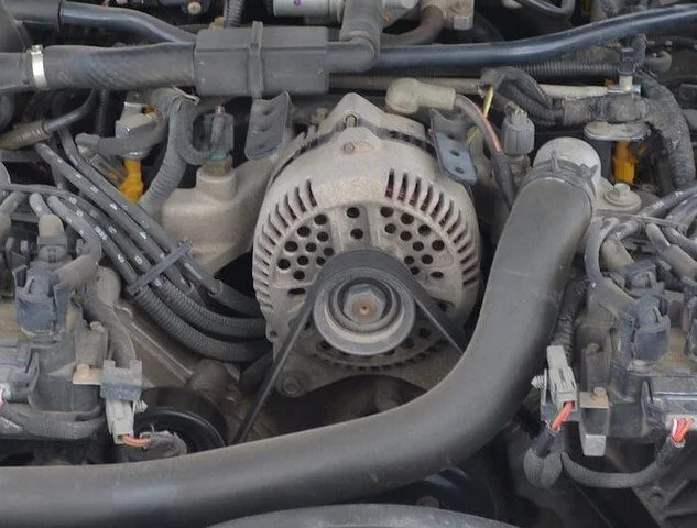
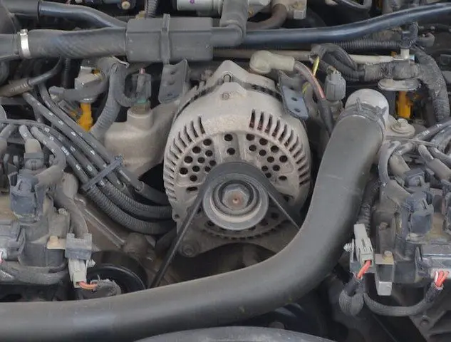
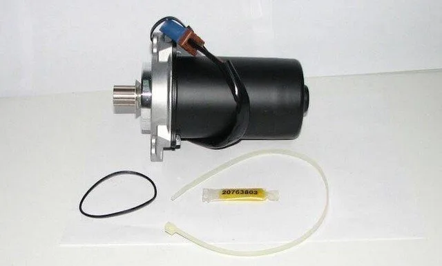
An Electric Power Steering Motor:
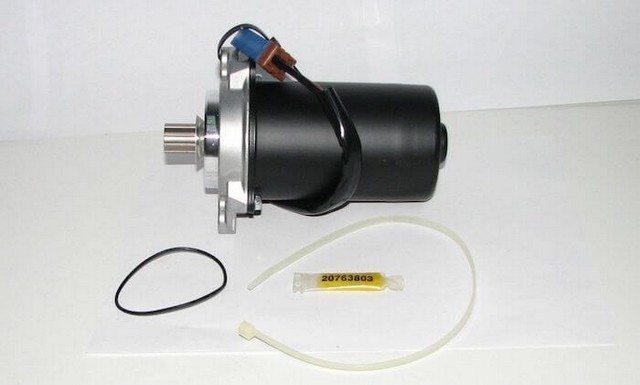
P0637 Electric Power Steering Motor
How Severe Is This DTC?
The severity of this code can vary greatly from a simple illuminated Check Engine light on a vehicle that operates normally to a stiff or irregular steering problem. Steering issues can become a safety concern when they do not receive immediate attention.
What Are Some of the Symptoms of the Code?
Symptoms of a P0637 trouble code may include:
Stiff or irregular steering
Noise when turning
Check Engine light illuminated
What Are Some of the Common Causes of the Code?
Causes
of this P0637 code may include:
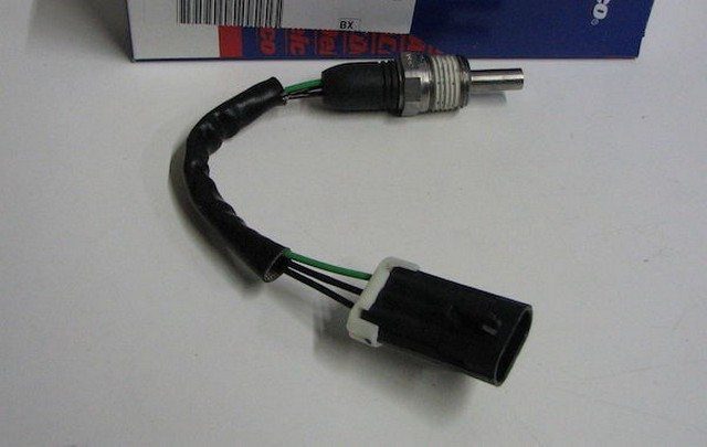
Faulty power steering pressure switch
Faulty power steering position switch
Faulty power steering control
A broken Powertrain Control Module ground strap or ground wire
Insufficient fluid level or leak
Blown fuse or fusible link (if applicable)
Corroded or damaged connector
Faulty or damaged wiring
Faulty PCM
What Are the P0637 Troubleshooting Steps?
The first step in the troubleshooting process for any malfunction is to search for Technical Service Bulletins (TSBs) for the specific vehicle by year, model, and powertrain. In some circumstances, this can save a lot of time in the long run by pointing you in the right direction.
The second step is to check the power steering fluid level and look for any possible leaks that could negatively impact the pressure supplied to the power steering controller and associated components. Proper fluid pressure plays a key role in the operation of this circuit. Then locate all components of this circuit and perform a thorough visual inspection to check that the associated wiring does not show obvious defects such as scraping, rubbing, bare wires, or burn marks. Next, check the connectors for security, corrosion, and damaged pins. This process should include the power steering controller, associated sensors, switches, and the PCM. The condition of the Controller Area Network (CAN) is essential to this troubleshooting process as a damaged wiring harness makes it very difficult to identify faulty components.
Advanced Steps
Advanced steps become very vehicle-specific and require appropriate advanced equipment to perform accurately. These procedures require a digital multimeter and the vehicle-specific technical references. Voltage requirements vary depending on the specific year and model of the vehicle.
Voltage Checks
Specific troubleshooting guidelines must be referenced to determine the required voltage ranges in the power steering control circuit. Based on the configuration, several power steering components are incorporated. Power steering controllers, pressure switches, and position sensors require different voltages to operate correctly depending on the specific vehicle involved.
If this process identifies the absence of a power source or ground, continuity tests may be required to verify the integrity of the wiring, connectors, and other components. Continuity tests should always be performed with the power disconnected from the circuit, and normal readings for wiring and connections should be 0 ohms of resistance. Resistance or lack of continuity is an indication of faulty wiring that is open or shorted and must be repaired or replaced.
What Are the Common Repairs for This Code?
Replacing the power steering pressure switch
Replacing the power steering position switch
Replacing the blown fuse or fusible link (if applicable)
Repairing the power steering leak
Cleaning corrosion from connectors
Repairing or replacing faulty wiring
Replacing the power steering controller
Flashing or replacing the PCM
Note: Code P0637 often prevents