P0704 Clutch Switch Input Circuit Malfunction

What does it mean?

This diagnostic trouble code (DTC) is a generic powertrain code, meaning it applies to all vehicles manufactured from 1996 onwards (Ford, Honda, Mazda, Mercedes, VW, etc.). Although generic, specific repair steps may vary by make/model.

If a P0704 code has been stored in your OBD-II vehicle, it simply means the Powertrain Control Module (PCM) has detected a malfunction in the clutch switch input circuit. This code applies exclusively to vehicles equipped with manual transmissions.

Certain manual transmission functions are electronically monitored by the PCM. The gear lever position and clutch pedal position are among these functions. In some models, turbine input and output speed are also monitored to determine the degree of clutch slippage.

The clutch is a mechanical coupling that connects the engine to the transmission. In most cases, it is actuated using a rod (with a pedal at the end) that pushes the piston of a hydraulic clutch master cylinder mounted on the firewall. When the clutch master cylinder is pressed, hydraulic fluid is pushed into the slave cylinder (mounted on the transmission). The slave cylinder actuates the clutch pressure plate, allowing the engine to be engaged and disengaged from the transmission as needed. Some models use a cable clutch, but this type of system is becoming less common. Pressing the pedal with the left foot disengages the transmission from the engine. Releasing the pedal allows the clutch to engage the flywheel, propelling the vehicle in the desired direction.

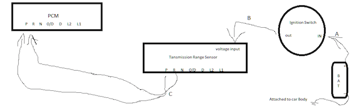
The main function of the clutch switch is to act as a safety device so the engine does not start with the transmission unintentionally engaged. The clutch switch is primarily designed to interrupt the starter signal (from the ignition switch) so the starter is only activated if the clutch pedal is pressed. The PCM and other controllers also use the clutch switch input for various engine control calculations, automated braking functions, as well as for implementing hill hold and start-stop functions.

The P0704 code relates to the clutch switch input circuit. Consult your vehicle’s service manual or All Data (DIY) for component locations and other specific information regarding this particular circuit for your vehicle.

Symptoms and Severity
Various driving, safety, and traction control functions may be interrupted when a P0704 code is stored. This code should be treated as urgent because of this.

Symptoms of a P0704 code may include:

  • Intermittent or failed engine starting
  • Reduced fuel efficiency
  • Excessive engine idle speed
  • The traction control system may be disabled
  • Safety functions may be disabled on some models

Possible causes for this code being set are:

  • Faulty clutch switch
  • Worn clutch pedal lever or clutch pedal pivot ring
  • Shorted or open wiring and/or connectors in the clutch switch circuit
  • Blown fuse or burned fuse link
  • PCM programming error or faulty PCM

Diagnostic and Repair Procedures

A scan tool, a digital volt/ohmmeter, and a service manual (or All Data DIY) for your vehicle are all the tools that will be needed to diagnose a P0704 code.

A visual inspection of the clutch switch circuit wiring is a good place to start your diagnosis. Test all system fuses and replace blown fuses as needed. Test the battery load, check battery cables and battery ground cables at this point. Also check the alternator output.

Locate the diagnostic connector, connect the scan tool, and retrieve all stored codes and freeze frame data. Note this information, as it may be helpful for further diagnosis. Clear the codes and test drive the vehicle to see if the code resets immediately.

If it does: Use the DVOM to check battery voltage at the clutch switch input circuit. Some vehicles are equipped with multiple clutch switches to accommodate multiple functions. Consult All Data DIY to determine your clutch switch configuration. If the input circuit has battery voltage, press the clutch pedal and check for battery voltage on the output circuit. If there is no voltage on the output circuit, suspect a faulty or misadjusted clutch switch. Also ensure the clutch pivot lever and pedal arm are mechanically sound. Check for play in the clutch pedal pivot ring.

If there is voltage on both sides of the clutch switch (when the pedal is pressed), check the clutch switch input circuit at the PCM. This could be a battery voltage signal or a reference voltage signal; consult your vehicle manufacturer’s specifications. If there is an input signal to the PCM, suspect a faulty PCM or a PCM programming error.

If there is no clutch switch input signal at the PCM connector, disconnect all associated controllers and use the DVOM to test the resistance of all circuits in the system. Repair or replace any shorted or open circuits (between the clutch switch and the PCM) as necessary.

Additional Diagnostic Notes:


Check system fuses with the clutch pedal pressed. Fuses that may appear normal during initial testing may fail when the circuit is placed under load.
Often, a worn clutch pivot arm or clutch pedal pivot ring can be misdiagnosed as a faulty clutch switch.

Mercury P1442 Code: EVAP System Vent Control Circuit Malfunction

Understanding the Mercury P1442 Diagnostic Trouble Code

The P1442 code is an OBD-II diagnostic trouble code specific to Mercury vehicles that indicates a malfunction in the Evaporative Emission Control (EVAP) system’s vent control circuit. This system is crucial for preventing fuel vapors from escaping into the atmosphere, making the P1442 code both an emissions compliance issue and a potential drivability concern. When this code appears, your vehicle’s powertrain control module (PCM) has detected an electrical problem within the circuit that controls the EVAP canister vent solenoid.

What is the EVAP System and How Does It Work?

The Evaporative Emission Control system is designed to capture and store fuel vapors from the fuel tank, preventing them from being released into the atmosphere. The system consists of several key components:

  • Fuel tank and cap
  • Charcoal canister
  • Vent control valve/solenoid
  • Purge control valve/solenoid
  • Various hoses and connectors

When the engine is off, fuel vapors are absorbed by the charcoal canister. During engine operation, the PCM opens the purge valve, allowing stored vapors to be drawn into the intake manifold and burned during combustion. The vent control valve, which is the component associated with P1442, regulates fresh air flow into the system and seals the system during leak tests.

Technical Specifications of P1442 Code

The P1442 code is manufacturer-specific, meaning its exact definition can vary between different Mercury models. However, the general interpretation remains consistent across most applications:

  • Code Type: Manufacturer Specific (Mercury/Ford)
  • ICD Definition: EVAP System Vent Control Circuit Malfunction
  • System Affected: Evaporative Emissions Control
  • Severity: Moderate – Can affect fuel economy and emissions compliance
  • Drivability: Usually minimal immediate impact on performance

Common Symptoms and Causes of P1442 in Mercury Vehicles

Recognizing the symptoms and understanding the potential causes of P1442 is essential for accurate diagnosis and repair. While this code doesn’t typically cause severe drivability issues, it can lead to failed emissions tests and reduced fuel efficiency over time.

Primary Symptoms of P1442 Code

When the P1442 code is stored in your Mercury’s PCM, you may notice several indicators:

  • Illuminated Check Engine Light (MIL)
  • Possible failed emissions test
  • Reduced fuel economy in some cases
  • Fuel odor near the vehicle (if vent valve is stuck open)
  • Difficulty refueling (if vent valve is stuck closed)
  • No noticeable drivability issues in most instances

Root Causes of P1442 Diagnostic Trouble Code

The P1442 code can be triggered by various issues within the EVAP vent control circuit. Understanding these potential causes will streamline your diagnostic process:

  • Faulty EVAP Canister Vent Solenoid: The most common cause, where the solenoid fails electrically or mechanically
  • Damaged Wiring or Connectors: Corroded, broken, or shorted wires in the vent control circuit
  • Poor Electrical Connections: Loose or corroded connectors at the vent solenoid or PCM
  • Blown Fuse: A fuse specifically protecting the EVAP system circuits
  • Failed PCM: Rare, but possible if all other components test correctly
  • Blocked or Pinched Vent Hose: Physical obstruction preventing proper vent operation

Professional Diagnostic Procedure for P1442 Code

Proper diagnosis of P1442 requires a systematic approach using appropriate tools and following manufacturer-recommended procedures. This section outlines a comprehensive diagnostic strategy that technicians use to identify the root cause efficiently.

Required Tools and Safety Precautions

Before beginning diagnosis, ensure you have the proper equipment and observe necessary safety measures:

  • Digital Multimeter (DMM) with resistance and voltage testing capabilities
  • Quality OBD-II scanner capable of reading manufacturer-specific codes
  • Vehicle service manual or repair database for wiring diagrams
  • Smoke machine for EVAP system leak testing (professional applications)
  • Safety glasses and gloves
  • Well-ventilated work area
  • Fire extinguisher nearby when working with fuel system components

Step-by-Step Diagnostic Process

Follow this systematic approach to diagnose P1442 accurately:

  • Step 1: Verify the code with an OBD-II scanner and check for additional codes
  • Step 2: Perform visual inspection of EVAP system components, wiring, and connectors
  • Step 3: Check the vent solenoid electrical connector for corrosion or damage
  • Step 4: Test vent solenoid resistance and compare to specifications (typically 20-40 ohms)
  • Step 5: Check for power and ground at the vent solenoid connector with ignition on
  • Step 6: Test wiring continuity between the vent solenoid and PCM
  • Step 7: Perform functional test of the vent solenoid using a scan tool bidirectional controls
  • Step 8: Inspect vent hoses for restrictions, damage, or improper routing

Repair Procedures and Prevention Strategies

Once the root cause of P1442 has been identified through proper diagnosis, appropriate repairs can be performed. This section covers common repair procedures and how to prevent recurrence of this issue.

Common Repair Solutions for P1442

Depending on the diagnostic findings, one or more of these repairs may be necessary:

  • Replacing EVAP Vent Solenoid: The most common repair when the solenoid tests faulty
  • Repairing Wiring Harness: Addressing damaged wires with proper splicing techniques
  • Cleaning or Replacing Connectors: Addressing corrosion issues in electrical connections
  • Replacing Fuses: If a blown fuse is identified as the cause
  • Clearing Vent Pathways: Removing obstructions from vent hoses or tubes
  • PCM Replacement/Reprogramming: Rarely needed, only after eliminating all other possibilities

Preventive Maintenance and Long-Term Solutions

Preventing recurrence of P1442 and similar EVAP system codes involves regular maintenance and awareness:

  • Regularly inspect EVAP system components during routine maintenance
  • Keep the area around the EVAP canister and vent solenoid clean and free of debris
  • Address any fuel system issues promptly to prevent additional strain on EVAP components
  • Always use a quality fuel cap that seals properly
  • Have emissions system checked annually, especially before required testing
  • Address any check engine lights immediately to prevent additional system damage

Technical Considerations and Professional Insights

Successfully addressing P1442 requires understanding some technical nuances specific to Mercury vehicles and the EVAP system operation.

Vehicle-Specific Considerations for Mercury Models

Different Mercury models may have variations in their EVAP system design that affect diagnosis:

  • Mercury Sable/Taurus: Vent solenoid typically located near fuel tank
  • Mercury Grand Marquis: Often has more accessible EVAP components
  • Mercury Mountaineer: Higher ground clearance may affect component location
  • Model Year Variations: Earlier models may have different testing procedures
  • Engine Specifics: Different engines may have unique routing of EVAP components

When to Seek Professional Assistance

While some DIY enthusiasts can address P1442, certain situations warrant professional help:

  • If you lack proper diagnostic tools or technical expertise
  • When the root cause isn’t apparent after basic testing
  • If multiple EVAP codes are present simultaneously
  • When the vehicle is still under warranty
  • If you suspect PCM issues or complex electrical problems
  • When emissions testing deadlines are approaching

Successfully diagnosing and repairing P1442 requires patience, proper tools, and methodical troubleshooting. By following the procedures outlined in this guide, you can effectively address this EVAP system issue in your Mercury vehicle, restore proper emissions control function, and extinguish that check engine light with confidence.

P0705 Transmission Range Sensor Circuit Malfunction

What does it mean?

This is a generic powertrain code, meaning it covers all makes/models from 1996 onward. However, specific troubleshooting steps vary by vehicle.


The P0705 diagnostic trouble code (DTC) refers to an external or internal switch on the transmission whose function is to signal the powertrain control module (PCM) or transmission control module (TCM) the gear shift position – P, R, N, and D positions (Park, Reverse, Neutral, and Drive). Reverse lights may also operate via the transmission range sensor (TRS) if it is an external component.

The code tells you that the computer has recognized a failure in the TRS sensor. The sensor sends either an incorrect signal or no signal to the computer that identifies the gear position. The computer receives signals from the vehicle speed sensor as well as the TRS.

When the vehicle is moving and the computer receives conflicting signals, such as the TRS signal indicating the vehicle is in park, but the speed sensor indicates it is moving, the P0705 code is set.

External TRS failure is common as age and mileage accumulate. It is exposed to weather and elements, and like any printed circuit board, it tends to corrode over time. The advantage is that it is not an expensive repair and easy to replace with little automotive repair experience.

Later models with the transmission range sensor located in the valve body are a different ball game. The range sensor is separated from the neutral safety switch and the reverse light switch. Its mission is the same, but its replacement has become a more serious matter both in difficulty and expense. The simplest method to determine which type is used on your vehicle is to search for the part on your local auto parts website. If it is not listed, it is internal.

Symptoms

Symptoms of a P0705 DTC may include:

Malfunction Indicator Light (MIL) illumination with P0705 DTC code set
Reverse lights may not work
It may be necessary to move the gear shift lever slightly up and down for better contact to allow the starter to engage and start the engine.
It may be impossible to engage the starter
In some cases, the engine only starts in neutral
May start in any gear
Irregular shift RPM
Decreased fuel economy
Transmission may display delayed engagement
Toyota vehicles, including trucks, may display erratic instrument readings

Causes

Potential causes of this DTC may include:

TRS is loose and poorly adjusted
Transmission range sensor is faulty
Bad connector at the external TRS, loose, corroded, or bent pins
Wiring harness shorted on the external sensor due to rubbing on the transmission linkage
Blockage in the valve body internal TRS orifice or faulty sensor

Diagnostic Steps and Possible Solutions

Replacing an internal TRS requires using a Tech II for diagnosis, followed by draining the transmission and removing the pan. The sensor is located at the bottom of the valve body, which is responsible for all transmission functions. The sensor is continuously immersed in hydraulic fluid, which causes housing issues. Many times, hydraulic flow is restricted or the O-ring has caused the problem.

Regardless, this is a complicated process best left to a transmission specialist.

Replacing external transmission range sensors:

Block the wheels and set the parking brake.
Place the transmission in neutral
Locate the transmission shift linkage. On front-wheel drive vehicles, it will be located on top of the transaxle. On rear-wheel drive vehicles, it will be on the driver’s side
Remove the electrical connector from the TRS sensor and inspect it carefully. Look for corroded, bent, or pushed-back (missing) pins in the sensor. Check the connector on the harness for the same, but in this case, there are female ends that must be in place. The harness connector can be replaced separately if it cannot be salvaged by cleaning or straightening the female connectors. Place a small amount of dielectric grease in the connector before reconnecting
Look at the wiring harness location and ensure it is not rubbing on the shift linkage. Check for broken or shorted wires due to lack of insulation
Check that the sensor is not loose. If it is loose, set the parking brake and transmission in neutral. Turn the key and rotate the TRS until the reverse lights come on. At this point, tighten the two TRS bolts. If the vehicle is a Toyota, you must rotate the TRS until a 5mm drill bit fits into the housing hole before tightening
Remove the nut holding the shift lever and lift the lever
Remove the electrical connector from the sensor
Remove the two bolts securing the sensor to the transmission. Unless you want to practice magic and turn this ten-minute job into several hours, do not drop the two bolts into no man’s land
Lift the sensor from the transmission
Look at the new sensor and ensure the markings on the shaft and housing, where it is marked “neutral,” are aligned
Install the sensor on the shift lever shaft and install and tighten the two bolts
Plug in the electrical connector
Reinstall the shift lever and tighten the nut
Additional note: The external TR sensor found on some Fords may be referred to as an MLPS or manual lever position sensor.

Related transmission range sensor codes: P0705, P0706, P0707, P0708, and P0709.

P0706 Transmission Range Sensor “A” Circuit Range/Performance

What Does It Mean?


This diagnostic code (DTC) is a generic powertrain code, meaning it applies to vehicles equipped with OBD-II. Although generic, specific repair steps may vary by make/model.


P0706 is a generic powertrain DTC in the transmission control subsystem group. It is a type “C” DTC. Type “C” DTCs are not emissions-related, so the powertrain control module (PCM) does not illuminate the check engine light and does not store freeze frame data.

The transmission range sensor may be called a park/neutral (PN) switch or neutral safety switch. Its purpose is to inform the PCM of the gearshift lever position and allow the engine to start only in park and neutral positions. The PCM sends a voltage reference to the sensor, and the sensor returns a different voltage to the PCM based on the gear the shift lever is in. If the return voltage is not what it should be, this code will be set.

Example of an external transmission range sensor (TRS):
Transmission Range Sensor TRS (external type)
Dorman TRS Image

Symptoms

and Code Severity
Because the neutral safety switch is part of the transmission range sensor, the vehicle may start in any gear position and/or the PCM will force the transmission into “limp” mode. In this mode, there is a noticeable lack of power, especially from a complete stop.

There is a serious safety issue when this code is present due to the possibility of the vehicle starting in gear, causing it to move upon startup. This issue must be fixed immediately.

Causes


Possible causes for this code being set include:

Faulty transmission range sensor
Misadjusted transmission range sensor
Open or shorted transmission range sensor harness
Faulty PCM
Diagnostic and Repair Procedures
There are two possible conditions that will cause this code to be set:

Condition No. 1 – The PCM detects drive or reverse during vehicle startup

Condition No. 2 – The PCM detects park or neutral and the following conditions exist for 10 seconds or more:> Throttle position is 5% or greater:> Engine torque is greater than 50 ft.lbs. > Vehicle speed is greater than 20 mph

In my experience, this code is most common on four-wheel drive trucks that have been “four-wheeled” and have sustained damage to the range sensor and/or harness. It would be very rare for a faulty PCM to cause this code. Diagnosing this code is quite straightforward. SET THE PARKING BRAKE.

Begin with a thorough visual inspection of the range sensor and cable harness. Repair any damage found. Does the vehicle start in reverse/drive? If it starts, unplug the range sensor and try starting it in reverse. If it still starts, suspect a short in the harness. If it does not start, suspect a faulty or misadjusted range sensor.

Related Transmission Range Sensor Codes: P0705, P0706, P0707, P0708, and P0709.

P0707 Transmission Range Sensor “A” Circuit Low

What does it mean?

This diagnostic trouble code (DTC) is a generic powertrain code, meaning it applies to vehicles equipped with OBD-II. Although generic, specific repair steps may vary by make/model.

It is a powertrain diagnostic trouble code (DTC) for the transmission control system. It is a type “C” DTC that does not trigger the check engine light but may cause the overdrive (O/D) or D4 indicator to flash. Only emission-related codes trigger the check engine light.

The transmission range sensor operates by receiving a voltage signal. It is changed or rerouted based on the gear lever position. In the DTC description, it indicates a low state in the circuit. This refers to a low or no voltage signal returning to the PCM. Refer to the diagram in the diagnostic/repair section below.

Example of an external transmission range sensor (TRS):
Transmission Range Sensor TRS (external type)

Symptoms and severity of the code

The engine may not start due to the park/neutral switch, which is internal to most transmission range sensors. There may be irregular shifting or even the possibility of starting in gear. There could also be a lack of power due to the transmission controls being in “limp home” mode.

There is certainly a safety factor to consider with this code, and it should be repaired as soon as possible.

The possible causes for this code being set are as follows:

  • Faulty transmission range sensor
  • Open or shorted wiring
  • Misadjusted transmission range sensor
  • Faulty PCM
  • Diagnostic and repair procedures
  • To diagnose this code, we first need a basic understanding of two things:

1. What is an open circuit?

An open circuit is a circuit that does not form a complete loop from the battery negative to the battery positive. For example, when a light bulb stops working because the filament breaks in two, the circuit would be open at the broken filament.

2. What is a short circuit?

A short circuit occurs when the battery negative comes into contact with the battery positive without any type of load between them. In other words, there must be a component (e.g., a light, motor, sensor, etc.) in the circuit. A short circuit is like dropping a key on your car battery, and it touches both terminals and sparks. This is called a direct short.

Now, with basic circuit 101 out of the way, refer to the diagram below. An open circuit at point A, B, or C would cause low voltage at the PCM. A short circuit at the same points would cause a blown fuse and again low voltage at the PCM. Both conditions will set DTC P0707.

To determine the exact cause of the DTC, simply check the voltage at points A, B, and C. If there is voltage at A and B but not at C, suspect a faulty range sensor. If there is voltage at C, suspect shorted wiring or, in rare cases based on my experience, a faulty PCM. If there is voltage at A, check only the fuses.

Related transmission range sensor codes: P0705, P0706, P0707, P0708, and P0709.

Transmission Range Sensor “A” Circuit High

What does it mean?


This diagnostic code (DTC) is a generic powertrain code, meaning it applies to vehicles equipped with OBD-II. Although generic, specific repair steps may vary by make/model.


This is a generic powertrain diagnostic code (DTC) in the transmission subgroup. It is a “B” type DTC, meaning the Powertrain Control Module (PCM) or Transmission Control Module (TCM) will not illuminate the Check Engine light until the code setting conditions are detected on two consecutive key cycles (on-off, off-on).

The PCM or TCM uses the transmission range sensor, also called the inhibitor switch, to determine the gear lever position. If it receives signals indicating two different gear positions at the same time for more than 30 seconds, P0708 will be set. If this happens twice in a row, the Check Engine light will illuminate, and the transmission will be commanded into a “fail-safe” or “limp-home” mode.

Symptoms

and code severity
The Check Engine light will illuminate, accompanied by a noticeable lack of power when pulling away from complete stops because the transmission starts in third gear.

Continuing to drive the vehicle can lead to serious transmission damage. I recommend having it repaired immediately to avoid costly internal transmission repairs.

Causes


Causes

possible for setting this code are as follows:

Faulty transmission range sensor
Poorly adjusted gearshift cable/linkage
Damaged wiring
Poorly adjusted range sensor
(Rarely) PCM or TCM failure

Diagnostic and repair procedures
The transmission range sensor receives a twelve-volt signal from the ignition switch and sends a signal back to the PCM/TCM appropriate for the selected gear lever position.

In my experience, the most common causes of this code have been a faulty range sensor or a poorly adjusted gearshift cable/linkage.

Checking this circuit is easier with a scan tool, but if one is not available, there are still a few things you can check. Keep the key in the ON position with the engine off (KOEO). With a digital voltmeter, you can check each individual return signal circuit by backprobing the sensor while it is still connected. Have an assistant shift into each gear one by one. Each signal circuit should have voltage in one and only one position. If there is voltage on a circuit in more than one gear position, suspect a faulty range sensor.

In my experience, I have never seen a PCM/TCM be the cause of a DTC related to a range sensor. This doesn’t mean it’s not possible, because it is, it’s just not likely. However, I have seen a faulty PCM/TCM that was damaged by a short circuit in a range sensor. If you suspect a PCM/TCM failure, be sure to look for the cause of the damage before installing a new one to avoid causing the same damage to it.

Related transmission range sensor codes: P0705, P0706, P0708, P0708 and P0709

Mazda P1442 Code: EVAP System Leak Detection Pump Control Circuit

Understanding Mazda Diagnostic Trouble Code P1442

When your Mazda’s check engine light illuminates and you retrieve diagnostic trouble code P1442, you’re dealing with a specific issue within the Evaporative Emission Control (EVAP) system. This code indicates a malfunction in the Leak Detection Pump (LDP) Control Circuit, a critical component responsible for monitoring and maintaining the integrity of your vehicle’s fuel vapor containment system. The EVAP system prevents gasoline vapors from escaping into the atmosphere, and the leak detection pump is its primary diagnostic tool.

What is the EVAP System and Why It Matters

The Evaporative Emission Control system is a sealed network designed to capture and store fuel vapors from the fuel tank, preventing their release into the environment. This system includes several key components:

  • Fuel tank and cap
  • Charcoal canister (vapor storage)
  • Purge valve/solenoid
  • Vent valve
  • Leak Detection Pump (LDP)
  • Various hoses and connectors

Modern vehicles like Mazdas use sophisticated monitoring systems to ensure the EVAP system remains leak-free, which is where the leak detection pump plays a crucial role.

The Role of the Leak Detection Pump in Mazda Vehicles

The Leak Detection Pump is an electrically-operated pump that creates vacuum or pressure within the EVAP system to test for leaks. When the vehicle’s computer (PCM) initiates a self-test, it activates the LDP to pressurize the system. The PCM then monitors the system’s ability to hold pressure. If the control circuit for this pump malfunctions, the PCM cannot perform this critical test and will set code P1442.

Common Symptoms of Mazda P1442 Code

Recognizing the symptoms associated with code P1442 can help you address the issue promptly. While some vehicles may show no drivability concerns, others may exhibit noticeable signs that warrant immediate attention.

Illuminated Check Engine Light

The most common and obvious symptom is the illumination of the check engine light on your dashboard. This warning indicates the Powertrain Control Module (PCM) has detected a fault in the LDP control circuit and stored code P1442 in its memory.

Failed Emissions Testing

Since the EVAP system is part of your vehicle’s emissions control system, an active P1442 code will typically cause your Mazda to fail state emissions inspections. This can prevent you from renewing your vehicle registration until the issue is resolved.

Potential Fuel Odor

While not always present with P1442, you might notice a faint gasoline smell around your vehicle if the EVAP system isn’t functioning correctly. This occurs when fuel vapors aren’t being properly contained and processed through the system.

No noticeable drivability issues

Many Mazda owners report no change in vehicle performance, fuel economy, or driving characteristics when P1442 is present. The system primarily affects emissions rather than engine operation, which can make the code easy to ignore—though not recommended.

Primary Causes of P1442 in Mazda Vehicles

Several issues can trigger the P1442 diagnostic trouble code in Mazda models. Understanding these potential causes will help you diagnose the problem efficiently and accurately.

Faulty Leak Detection Pump

The most direct cause of P1442 is a malfunctioning leak detection pump itself. The LDP contains electrical components, valves, and a diaphragm that can fail over time. Common pump failures include:

  • Electrical motor failure
  • Stuck or seized pump mechanism
  • Internal diaphragm damage
  • Corrosion or water intrusion

Electrical Circuit Problems

Since P1442 specifically references the “control circuit,” wiring issues are a frequent culprit. These can include:

  • Damaged or frayed wiring to the LDP
  • Corroded or loose electrical connectors
  • Blown fuses affecting the LDP circuit
  • Poor ground connections
  • Short circuits or open circuits in the control wiring

PCM Software Issues

In some Mazda models, outdated PCM programming can cause false P1442 codes. Mazda has issued Technical Service Bulletins (TSBs) for certain vehicles addressing EVAP system diagnostic improvements through PCM reprogramming.

Step-by-Step Diagnostic Procedure for P1442

Proper diagnosis of P1442 requires a systematic approach to identify the root cause efficiently. Follow these steps to pinpoint the issue accurately.

Initial Visual Inspection

Begin with a thorough visual examination of the EVAP system components:

  • Locate the leak detection pump (typically near the fuel tank or in the engine bay)
  • Check all electrical connections for corrosion, damage, or looseness
  • Inspect wiring harness for chafing, cuts, or burn marks
  • Verify the integrity of vacuum hoses connected to the LDP
  • Check relevant fuses in the engine compartment and interior fuse boxes

Electrical Circuit Testing

Using a digital multimeter, perform these electrical tests:

  • Check for battery voltage at the LDP power supply wire with ignition ON
  • Verify ground circuit integrity
  • Test control signal from PCM using a NOID light or oscilloscope
  • Measure circuit resistance for opens or shorts
  • Compare readings against manufacturer specifications

Leak Detection Pump Functional Testing

If electrical circuits test normal, proceed to functional testing of the LDP:

  • Command the LDP using a professional scan tool
  • Listen for pump activation sounds
  • Test pump resistance against factory specifications
  • Check for proper vacuum/pressure generation
  • Perform mechanical operation tests if applicable

Repair Procedures and Cost Considerations

Once you’ve identified the root cause of P1442, you can proceed with the appropriate repair strategy.

Leak Detection Pump Replacement

Replacing a faulty LDP is typically straightforward:

  • Disconnect the negative battery cable for safety
  • Locate and disconnect electrical connector from old LDP
  • Remove vacuum hoses, noting their positions for reassembly
  • Unbolt mounting hardware and remove the pump
  • Install new pump, reconnect all hoses and electrical connections
  • Clear codes and perform readiness monitor drive cycle

Wiring Repair Techniques

For circuit issues, proper repair is essential:

  • Repair damaged wires using solder and heat shrink tubing
  • Replace damaged connectors with OEM-quality parts
  • Ensure proper strain relief and routing of repaired wiring
  • Protect repairs from moisture and heat exposure
  • Test circuit operation before reassembly

Cost Estimation for P1442 Repairs

Repair costs for P1442 vary significantly based on the cause:

  • Leak Detection Pump replacement: $150-$400 (parts) + 1-2 hours labor
  • Wiring repair: $100-$300 (typically 1-2 hours labor)
  • PCM reprogramming: $100-$200 at dealership
  • Diagnostic time: 0.5-1.5 hours typically charged

Prevention and Maintenance Tips

While some causes of P1442 are unavoidable, proper maintenance can reduce the likelihood of recurrence.

Regular EVAP System Inspection

Include EVAP system components in your routine maintenance checks:

  • Visually inspect LDP and connections during oil changes
  • Check for cracked or brittle vacuum hoses
  • Ensure fuel cap is properly tightened after refueling
  • Address any check engine lights promptly

Proper Electrical Connection Maintenance

Protect electrical components from moisture and corrosion:

  • Apply dielectric grease to electrical connectors
  • Ensure wiring harnesses are properly secured
  • Address any rodent infestation issues promptly
  • Avoid pressure washing engine compartment directly at electrical components

Code P1442 in your Mazda, while not typically causing immediate drivability issues, should be addressed promptly to maintain emissions compliance and prevent potential future problems. With proper diagnosis and repair, this issue can be resolved effectively, restoring your vehicle’s EVAP system to proper operation.

Transmission Range Sensor “A” Circuit High

What does it mean?


This diagnostic trouble code (DTC) is a generic powertrain code, meaning it applies to vehicles equipped with OBD-II. Although generic, specific repair steps may vary by make/model.

This is a generic powertrain diagnostic trouble code (DTC) in the transmission subgroup. It is a type “B” code, meaning the Powertrain Control Module (PCM) or Transmission Control Module (TCM) will not illuminate the Check Engine light unless the conditions for setting the code are present for two consecutive key cycles (key on-off, off-on).

The PCM/TCM uses the transmission range sensor, sometimes called the inhibitor switch, to identify which gear position the shift lever is in. The code definition itself explains the issue causing the code; the signal from the range sensor is not present all the time or is intermittently missing.

Symptoms

and severity of the code
After the second key cycle, the PCM/TCM will illuminate the Check Engine light and force the transmission into “Limp-home” or “fail-safe” mode. There will be a noticeable loss of power, more visible when taking off from complete stops. In this mode, the transmission starts in third gear, which is hard on the transmission’s internal clutches.

Based on my experience, this can cause severe internal damage to the transmission, so it should be fixed as soon as possible. Avoid using the vehicle until repairs can be made.

Causes


The possible

causes for this code being set are:

Faulty transmission range sensor
Faulty wiring
(Rarely) Faulty PCM or TCM
Diagnostic and Repair Procedures
The transmission range sensor receives a 12-volt signal from the ignition switch and then sends a 12-volt signal, on the appropriate circuit based on the gear position, to the PCM/TCM.

P0709 is set when the signal is missing at the PCM/TCM. A scan tool with live data capability is the most accurate way to diagnose this DTC, but if unavailable, here are some items that can be checked with a digital volt-ohmmeter (DVOM). Based on my experience, the most common cause of intermittent signal issues is related to wiring.

In this case, a close visual inspection of the transmission range sensor wiring harness and the internal contacts of the range sensor connector should be performed first and thoroughly. If anything is found suspicious during the inspection, repair the issue, clear the codes, and test the vehicle. If the DTC returns, set the DVOM to volts and probe the appropriate circuits at the PCM/TCM and “wiggle” the harness at and leading to the range sensor. If no intermittent voltage loss is seen on the multimeter, suspect a faulty range sensor.

Related Transmission Range Sensor Codes: P0705, P0706, P0709, P0709, and P0709

Transmission Fluid Level Sensor Circuit

What Does It Mean?


This generic powertrain diagnostic trouble code (DTC) generally applies to OBD-II equipped vehicles that have a transmission fluid level sensor. Vehicle makes may include, but are not limited to, GM, Chevrolet, Ford, Dodge, Ram, Toyota, Hyundai, etc. This code is rare.

The Transmission Fluid Level (TFL) sensor is used to illuminate a warning light on the dashboard in case of low fluid level.

When the fluid level is within an acceptable range, the switch is grounded. When the transmission fluid drops below a predetermined level, the switch opens and a “low transmission fluid level” warning appears on the dashboard.

TFL sensors receive a reference voltage from the PCM. The PCM monitors the circuit and when it recognizes that the switch has opened, it activates the low fluid level warning on the instrument cluster.

Code P070A is set when the PCM detects a malfunction in the transmission fluid level sensor circuit. Related codes include P070B, P070C, P070D, P070E, and P070F.

Code Severity and Symptoms
The severity of this transmission code is moderate to severe. In some cases, this code and related codes may indicate a low transmission fluid level which, if left unaddressed, can damage the transmission. It is a good idea to address this code as soon as possible.

Symptoms of a P070A trouble code may include:

Low transmission fluid warning light illuminated
Check engine light
Transmission performance issues
Common causes of this DTC code

Causes

Possible causes of this code may include:

Faulty transmission fluid level sensor
Low transmission fluid level
Wiring problems
Faulty PCM
Diagnostic and repair procedures
Start by checking the transmission fluid level and condition according to the manufacturer’s recommendations. Then, inspect the transmission fluid level sensor and its corresponding wiring. Look for loose connections, damaged wiring, etc. If damage is detected, repair as necessary, clear the code, and see if it returns. Next, check for Technical Service Bulletins (TSBs) related to the issue. If nothing is found, you will need to proceed with step-by-step diagnosis of the system.

The following is a generalized procedure, as tests for this code vary by vehicle. To accurately test the system, you will need to refer to the manufacturer’s diagnostic flowchart.

Check the wiring
Before continuing, you will want to consult factory wiring diagrams to determine which wires are which. Autozone offers free online repair manuals for many vehicles, and ALLDATA offers single-vehicle subscriptions.

Check the reference voltage side of the circuit
Ignition on, use a digital multimeter set to DC volts to check the reference voltage (usually 5 or 12 volts) from the PCM. To do this, connect the negative meter lead to ground and the positive meter lead to the sensor B+ terminal on the harness side of the connector. If no reference signal is present, set the meter to ohms (ignition off) between the reference voltage pin on the TFL and the reference voltage pin on the PCM. If the meter reads out of limits (OL), there is an open circuit between the PCM and the sensor that will need to be located and repaired. If the meter reads a numerical value, there is continuity.

If everything is okay up to this point, you will want to verify that the PCM is powered. To do this, turn the ignition on and set the meter to DC volts. Connect the positive multimeter lead to the PCM’s reference voltage terminal and the negative lead to ground. If there is no reference voltage from the PCM, the PCM is likely faulty. However, PCMs rarely fail, so it is a good idea to double-check your work up to this point.

Check the ground side of the circuit
Ignition off, use a digital multimeter set to ohms to check for continuity. Connect the meter between the transmission fluid level sensor’s ground terminal and chassis ground. If the meter reads a numerical value, there is continuity. If the meter reads out of limits (OL), there is an open circuit between the PCM and the sensor that will need to be located and repaired.

Check the sensor
If everything checks out at this point, the sensor is likely faulty. To check this, turn the ignition off and set your multimeter to read ohms. Remove the connector from the transmission fluid level sensor and connect the meter to the sensor’s terminals. If the meter reads out of limits (OL), the sensor is open internally and must be replaced.

P070B Transmission Fluid Level Sensor Circuit Range/Performance

What Does It Mean?


This generic powertrain diagnostic trouble code (DTC) generally applies to OBD-II equipped vehicles that have a transmission fluid level sensor. Vehicle makes may include, but are not limited to, GM, Chevrolet, Ford, Dodge, Ram, Toyota, Hyundai, etc. This code is rare.

The Transmission Fluid Level (TFL) sensor is used to illuminate a warning light on the dashboard in case of low fluid level.

When the fluid level is within an acceptable range, the switch is grounded. When the transmission fluid drops below a predetermined level, the switch opens and a “low transmission fluid level” warning appears on the dashboard.

TFL sensors receive a reference voltage from the PCM. The PCM monitors the circuit and when it recognizes that the switch has opened, it activates the low fluid level warning on the instrument cluster.

Code P070B is set when the PCM detects a malfunction in the range or performance of the transmission fluid level sensor. Related codes include P070A, P070C, P070D, P070E, and P070F.

Code Severity and Symptoms
The severity of this transmission code is moderate to severe. In some cases, this code and related codes may indicate a low transmission fluid level which, if left unaddressed, can damage the transmission. It is a good idea to address this code as soon as possible.

Symptoms of a P070B trouble code may include:

Low transmission fluid warning light illuminated
Check engine light illuminated
Transmission performance issues
Common causes of this DTC code

Causes

Possible causes of this code may include:

Faulty transmission fluid level sensor
Low transmission fluid level
Wiring problems
Faulty PCM
Diagnostic and Repair Procedures
Start by checking the transmission fluid level and condition according to the manufacturer’s recommendations. Then, inspect the transmission fluid level sensor and its corresponding wiring. Look for loose connections, damaged wiring, etc. If damage is detected, repair as necessary, clear the code, and see if it returns. Next, check for Technical Service Bulletins (TSBs) related to the issue. If nothing is found, you will need to proceed with step-by-step diagnosis of the system.

The following is a generalized procedure, as tests for this code vary by vehicle. To accurately test the system, you will need to refer to the manufacturer’s diagnostic flowchart.

Check the Wiring
Before continuing, you will want to consult the factory wiring diagrams to determine which wires are which. Autozone offers free online repair manuals for many vehicles and ALLDATA offers single-vehicle subscriptions.

Check the Reference Voltage Side of the Circuit
Ignition on, use a digital multimeter set to DC volts to check the reference voltage (usually 5 or 12 volts) from the PCM. To do this, connect the negative meter lead to ground and the positive meter lead to the sensor B+ terminal on the harness side of the connector. If no reference signal is present, set the meter to ohms (ignition off) between the reference voltage pin on the TFL and the reference voltage pin on the PCM. If the meter reads out of limits (OL), there is an open circuit between the PCM and the sensor that will need to be located and repaired. If the meter reads a numerical value, there is continuity.

If everything is okay up to this point, you will want to verify that the PCM is powered. To do this, turn the ignition on and set the meter to DC volts. Connect the positive multimeter lead to the PCM’s reference voltage terminal and the negative lead to ground. If there is no reference voltage from the PCM, the PCM is likely faulty. However, PCMs rarely fail, so it is a good idea to double-check your work up to this point.

Check the Ground Side of the Circuit
Ignition off, use a digital multimeter set to ohms to check for continuity. Connect the meter between the transmission fluid level sensor’s ground terminal and chassis ground. If the meter reads a numerical value, there is continuity. If the meter reads out of limits (OL), there is an open circuit between the PCM and the sensor that will need to be located and repaired.

Check the Sensor
If everything checks out at this point, the sensor is likely faulty. To check this, turn the ignition off and set your multimeter to read ohms. Remove the connector from the transmission fluid level sensor and connect the meter to the sensor’s terminals. If the meter reads out of limits (OL), the sensor is open internally and must be replaced.