2025 Hyundai Santa Cruz: The Urban Adventure Truck

Redefining the Pickup for City Living

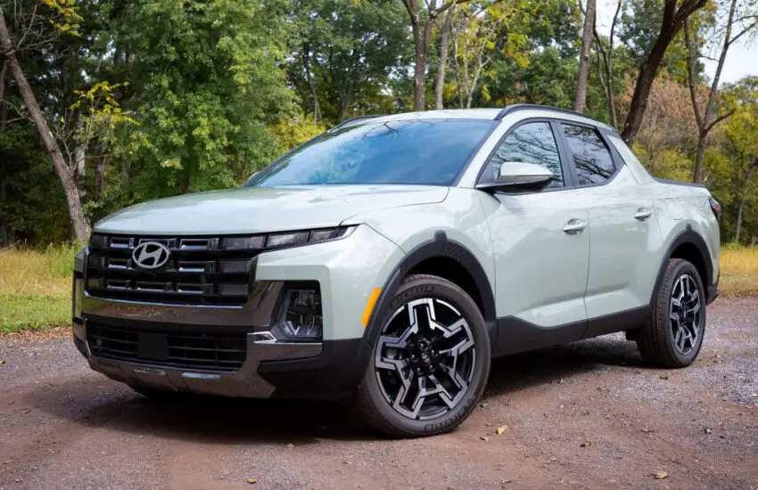
The automotive landscape is evolving, and the 2025 Hyundai Santa Cruz stands at the forefront of this transformation. Designed for those who need utility without the bulk of a traditional truck, this vehicle masterfully blends the comfort of an SUV with the functionality of a pickup. Its sleek, car-like profile and manageable size make it ideal for navigating tight urban streets and parking with ease, offering a driving experience that larger trucks simply cannot match.

Versatility Meets Modern Design

Under the hood, the Santa Cruz is expected to feature efficient yet capable engine options, providing ample power for daily commutes and weekend getaways. The innovative integrated bed is not just for show; it’s a practical space with features like a lockable tonneau cover and an available power outlet, perfect for securing gear or powering tools for a spontaneous project. The interior continues this theme of smart design, with a spacious, tech-forward cabin that prioritizes passenger comfort and connectivity, making every journey enjoyable.

Why It Appeals to Non-Truck Buyers

Many drivers are hesitant to commit to a conventional pickup due to its often cumbersome nature and rugged ride quality. The Santa Cruz directly addresses these concerns by delivering a smooth, refined ride akin to a premium crossover, coupled with a versatile bed that handles everything from grocery runs to outdoor adventure gear. It’s the ideal solution for active individuals and small families who require occasional hauling capacity without sacrificing daily drivability or fuel efficiency.

In a market saturated with similar options, the 2025 Hyundai Santa Cruz carves out a unique niche. It proves that you don’t need a massive vehicle to be prepared for anything, offering a compelling alternative that combines style, practicality, and innovation in one attractive package.

P2603 High Coolant Pump Control Circuit A

Symptoms and Severity

The severity is generally serious due to its impact on the cooling system. Since it is typically an electrical failure, the PCM cannot fully compensate for it. Partial compensation usually means the cooling fans run all the time (100% duty cycle).

Symptoms of a P2603 code may include:

  • Malfunction indicator light on
  • Overheating
  • The air conditioning system not working properly

Causes

Potential causes for this code being set are as follows:

  • Open in the coolant pump circuit – likely
  • Coolant pump failure – likely
  • PCM failure – unlikely

Diagnostic and Repair Procedures

A good starting point is always to check the Technical Service Bulletins (TSBs) for your specific vehicle. Your issue may be a known problem with a known fix released by the manufacturer and can save you time and money during diagnosis.

Next, locate the B coolant pump (CP-A) on your specific vehicle. This pump is typically found mounted at the front of the engine, on top of the engine, inside the wheel wells, or against the firewall. Once located, visually inspect the connector and wiring. Look for scratches, rubbing, bare wires, burns, or melted plastic. Disconnect the connector and carefully inspect the terminals (the metal parts) inside the connector. See if they appear burnt or have a greenish tint indicating corrosion. Use electrical contact cleaner and a plastic bristle brush if cleaning the terminals is necessary. Let it dry and apply electrical grease where the terminals make contact.

If you have a scan tool, clear the diagnostic codes from memory and see if the P2603 code returns. If it does not, the connections were likely your problem.

For this particular code, this is the most common area of concern, as are the relays/connections to the relays, with pump failure being the second most common.

If the code returns, we will need to test the pump and related circuits. Typically, there are 2 wires at each coolant pump. First, disconnect the harness going to the coolant pump. With a digital volt ohm meter (DVOM), connect one meter lead to one terminal of the pump. Connect the remaining meter lead to the other pump terminal. It should not be open or shorted. Check the resistance specifications for your specific vehicle. If the pump motor is open or shorted (infinite resistance or no resistance/0 ohms), replace the coolant pump.

If this test passes, with a DVOM, check that you have 12V at the coolant pump power circuit (red lead to the pump power circuit, black lead to a good ground). With a scan tool that can activate the coolant pump, turn on the coolant pump. If there is no 12 volts at the pump, repair the wiring from the PCM or relay to the pump, or possibly a faulty PCM.

If that checks out, verify the coolant pump ground circuit. Connect a test light to the positive 12V battery terminal (red terminal) and touch the other end of the test light to the ground circuit going to the coolant pump circuit ground. Using the scan tool to actuate the coolant pump, check if the test light illuminates each time the scan tool actuates the pump. If the test light does not illuminate, it would indicate a problem with the ground circuit. If it does light up, wiggle the wiring harness going to the pump to see if the test light flickers, indicating an intermittent connection.

If all previous tests have passed and you continue to get a P2603, it would most likely indicate a faulty coolant pump, although a faulty PCM cannot be ruled out until the coolant pump has been replaced. If in doubt, seek assistance from a qualified automotive diagnostician. PCMs need to be programmed or calibrated to the vehicle to be installed correctly.

Other similar coolant pump codes include P261A, P261B, P261C, and P261D.

P2604 Intake Air Heater A Circuit Performance

Code Severity and Symptoms

The severity of this code is normally moderate, but can be severe depending on the specific malfunction.

Symptoms of a P2604 diagnostic code may include:

  • Engine does not start
  • Longer than normal starting time
  • Check engine light illuminated
  • Rough idle in cold weather
  • Engine stalls

Causes

Generally, potential causes for this code include:

  • Faulty heating element relay
  • Defective heating element
  • Faulty temperature sensor
  • Corroded or damaged connector
  • Damaged or restricted air duct
  • Faulty or damaged wiring
  • Faulty blower motor
  • Faulty PCM

What are the most common repairs?

  • Replacement of the heating element
  • Replacement of the temperature sensor
  • Replacement of the heating element relay
  • Cleaning corrosion from connectors
  • Repairing or replacing wiring
  • Replacement of damaged air ducts
  • Replacement of the blower motor
  • PCM replacement

Diagnostic and Repair Procedures

The first step in the troubleshooting process for any malfunction is to search for Technical Service Bulletins (TSBs) for the specific vehicle by year, model, and powertrain. In some circumstances, this can save you considerable time in the long run by pointing you in the right direction.

The intake air heater circuit may not operate automatically if the ambient air or engine temperature is above the manufacturer’s set limit. The circuit should activate if it is commanded “ON” with a scan tool, or if power is manually applied.

Basic Steps

  • Check the heating element, does it turn “ON”
  • NOTE: Do not touch the heating element or heat shield
  • Check the blower motor, does it turn “ON”
  • Visually inspect the circuit connections and wiring for obvious faults
  • Visually inspect the condition of the air ducts for obvious faults
  • Check electrical connections for security and corrosion

Advanced Steps

Advanced steps become very vehicle-specific and require appropriate advanced equipment to perform accurately. These procedures require a digital multimeter and the specific vehicle technical references. Voltage requirements will be highly specific to the vehicle’s year, model, and diesel engine.

Specific Checks:

Note: On applications equipped with mass air flow sensors, the intake air temperature sensor is integrated into the sensor body. Consult the technical data to determine the correct pins associated with the sensor.

Specific checks should be performed using the troubleshooting guidelines for the specific vehicle using the technical manual or online reference material. These steps will guide you through the process of checking the power and ground for each component in the intake air heater circuit in the correct order. If voltage is correct for a component that is not functioning, that component is likely faulty and needs replacement. If power is not available to operate the circuit, continuity checks may be necessary to identify faulty wiring or components.

I hope the information in this article has helped point you in the right direction to correct your intake air heater circuit malfunction issue. This article is strictly informational, and the technical data and service bulletins specific to your vehicle should always take priority.

P2606 – Performance of the B Series Intake Air Heater Circuit

Code Severity and Symptoms

The severity of this code is normally moderate, but can be severe depending on the specific malfunction.

Symptoms of a P2606 diagnostic trouble code may include:

  • Engine does not start
  • Longer than normal starting time
  • Check engine light illuminated
  • Rough idle in cold weather
  • Engine stalls

Causes

Generally, potential causes for this code include:

  • Faulty heater element relay
  • Defective heater element
  • Faulty temperature sensor
  • Corroded or damaged connector
  • Damaged or restricted air duct
  • Faulty or damaged wiring
  • Faulty blower motor
  • Faulty PCM

What are the most common repairs?

  • Replacement of the heater element
  • Replacement of the temperature sensor
  • Replacement of the heater element relay
  • Cleaning corrosion from connectors
  • Repairing or replacing wiring
  • Replacement of damaged air ducts
  • Replacement of the blower motor
  • PCM replacement

Diagnostic and Repair Procedures

The first step in the troubleshooting process for any malfunction is to search for Technical Service Bulletins (TSBs) for the specific vehicle by year, model, and powertrain. In some circumstances, this can save significant time in the long run by pointing you in the right direction.

The intake air heater circuit may not operate automatically if the ambient air or engine temperature is above the manufacturer’s set limit. The circuit should activate if it is commanded “ON” with a scan tool, or if power is manually applied.

Basic Steps

  • Check the heater element, does it turn “ON”
  • NOTE: Do not touch the heating element or heat shield
  • Check the blower motor, does it turn “ON”
  • Visually inspect the circuit connections and wiring for obvious faults
  • Visually inspect the condition of the air ducts for obvious faults
  • Check electrical connections for security and corrosion

Advanced Steps

Advanced steps become very vehicle-specific and require appropriate advanced equipment to perform accurately. These procedures require a digital multimeter and vehicle-specific technical references. Voltage requirements will be highly dependent on the specific vehicle year, model, and diesel engine.

Specific Checks

Note: On applications equipped with mass air flow sensors, the intake air temperature sensor is integrated into the sensor body. Consult technical data to determine the correct pins associated with the sensor.

Specific checks should be performed using the troubleshooting guidelines for the specific vehicle using the technical manual or online reference material. These steps will guide you through the process of checking the power and ground for each component in the intake air heater circuit in the correct order. If voltage is correct for a component that is not functioning, that component is likely faulty and needs replacement. If power is not available to operate the circuit, continuity checks may be needed to identify faulty wiring or components.

Hopefully, the information in this article has helped point you in the right direction to correct your intake air heater circuit malfunction issue. This article is strictly informational, and technical data and service bulletins specific to your vehicle should always take priority.

P2605 Open Intake Air Heater Circuit B

Code Severity and Symptoms

The severity of this code is normally moderate, but can be severe depending on the specific malfunction.

Symptoms of a P2605 diagnostic trouble code may include:

  • Engine does not start
  • Longer than normal starting time
  • Check engine light illuminated
  • Rough idle in cold weather
  • Engine stalls

Causes

Generally, potential causes for this code include:

  • Faulty heater element relay
  • Defective heater element
  • Faulty temperature sensor
  • Corroded or damaged connector
  • Damaged or restricted air duct
  • Faulty or damaged wiring
  • Faulty blower motor
  • Faulty PCM

What are the most common repairs?

  • Replacement of the heater element
  • Replacement of the temperature sensor
  • Replacement of the heater element relay
  • Cleaning corrosion from connectors
  • Repairing or replacing wiring
  • Replacement of damaged air ducts
  • Replacement of the blower motor
  • PCM replacement

Diagnostic and Repair Procedures

The first step in the troubleshooting process for any malfunction is to search for Technical Service Bulletins (TSBs) for the specific vehicle by year, model, and powertrain. In some circumstances, this can save significant time in the long run by pointing you in the right direction.

The intake air heater circuit may not operate automatically if the ambient air or engine temperature is above the manufacturer’s set limit. The circuit should activate if it is commanded “ON” with a scan tool, or if power is manually applied.

Basic Steps

  • Check the heater element, does it turn “ON”
  • NOTE: Do not touch the heating element or heat screen
  • Check the blower motor, does it turn “ON”
  • Visually inspect the circuit connections and wiring for obvious faults
  • Visually inspect the condition of the air ducts for obvious faults
  • Check electrical connections for security and corrosion

Advanced Steps

Advanced steps become very vehicle-specific and require appropriate advanced equipment to perform accurately. These procedures require a digital multimeter and vehicle-specific technical references. Voltage requirements will be highly specific to the vehicle’s particular year, model, and diesel engine.

Specific Checks

Note: On applications equipped with mass air flow sensors, the intake air temperature sensor is integrated into the sensor body. Consult technical data to determine the correct pins associated with the sensor.

Specific checks should be performed using the troubleshooting guidelines for the specific vehicle using the technical manual or online reference material. These steps will guide you through the process of checking the power and ground for each component in the intake air heater circuit in the correct order. If voltage is correct for a component that is not functioning, that component is likely faulty and needs replacement. If power is not available to operate the circuit, continuity checks may be necessary to identify faulty wiring or components.

I hope the information in this article has helped point you in the right direction to correct your intake air heater circuit malfunction issue. This article is strictly informational, and technical data and service bulletins specific to your vehicle should always take priority…

Plastic Waste to Solar Fuel Innovation

Turning Plastic Waste into Solar Fuel

An entrepreneur named Julian Brown claims to have developed a method to convert plastic waste into fuel using only solar energy. His do-it-yourself process, which he calls “plastoline,” is reportedly conducted in his backyard with homemade equipment. This raises important questions about the viability and safety of such innovations in waste management and renewable energy.

The Conversion Process Explained

The method appears to combine two established mechanisms: pyrolysis and solar thermal energy. Pyrolysis involves heating plastic in the absence of oxygen to break it down into smaller hydrocarbon molecules, while concentrated solar power provides the necessary high temperatures. This dual approach could potentially transform common plastics like polyethylene and polypropylene into usable fuels without relying on grid electricity.

Potential Benefits and Applications

If successfully implemented, this technology could address multiple environmental challenges simultaneously. It offers a potential solution for plastic pollution by diverting waste from landfills and oceans. The resulting fuel could serve as an alternative energy source for various applications, potentially reducing dependence on fossil fuels. The solar-powered aspect makes it particularly interesting for remote areas with abundant sunlight and plastic waste problems.

Environmental and Safety Concerns

Despite the promising concept, significant questions remain about the process’s environmental impact and safety. Incomplete combustion during pyrolysis could release toxic compounds into the atmosphere. The quality and stability of the produced fuel need thorough testing to ensure it doesn’t damage engines or create additional pollution when burned. Proper handling of chemical byproducts and adherence to safety protocols would be essential for any scale implementation.

Future Prospects and Challenges

The development of plastic-to-fuel technology represents an intriguing intersection of waste management and renewable energy. While the concept shows promise for addressing plastic pollution and energy needs, substantial research and development are required to determine its practical feasibility. Regulatory frameworks would need to evolve alongside such innovations to ensure they deliver environmental benefits without creating new hazards.

P2609 – Intake Air Heater System Performance

Code Severity and Symptoms

The severity of this code is normally moderate, but can be severe depending on the specific malfunction.

Symptoms of a P2609 diagnostic trouble code may include:

  • Engine does not start
  • Longer than normal starting time
  • Check engine light illuminated
  • Rough idle in cold weather
  • Engine stalls

Causes

Generally, potential causes for this code include:

  • Faulty heater element relay
  • Defective heater element
  • Faulty temperature sensor
  • Corroded or damaged connector
  • Damaged or restricted air duct
  • Faulty or damaged wiring
  • Faulty blower motor
  • Defective PCM

What are the most common repairs?

  • Heater element replacement
  • Temperature sensor replacement
  • Heater element relay replacement
  • Cleaning corrosion from connectors
  • Repairing or replacing wiring
  • Replacing damaged air ducts
  • Blower motor replacement
  • PCM replacement

Diagnostic and Repair Procedures

The first step in the troubleshooting process for any malfunction is to search for Technical Service Bulletins (TSBs) for the specific vehicle by year, model, and powertrain. In some circumstances, this can save significant time in the long run by pointing you in the right direction.

The intake air heater circuit may not operate automatically if the ambient air or engine temperature is above the manufacturer’s set limit. The circuit should activate if commanded “ON” with a scan tool, or if power is manually applied.

Basic Steps

  • Check the heater element – does it turn “ON”
  • NOTE: Do not touch the heating element or heat shield
  • Check the blower motor – does it turn “ON”
  • Visually inspect circuit connections and wiring for obvious faults
  • Visually inspect condition of air ducts for obvious faults
  • Check electrical connections for security and corrosion

Advanced Steps

Advanced steps become very vehicle-specific and require appropriate advanced equipment to perform accurately. These procedures require a digital multimeter and vehicle-specific technical references. Voltage requirements will be highly dependent on the specific vehicle year, model, and diesel engine.

Specific Checks

Note: On applications equipped with mass air flow sensors, the intake air temperature sensor is integrated into the sensor body. Consult technical data to determine the correct pins associated with the sensor.

Specific checks should be performed using the troubleshooting guidelines for the specific vehicle using the technical manual or online reference material. These steps will guide you through the process of checking power and ground for each component in the intake air heater circuit in the correct order. If voltage is correct for a component that is not functioning, that component is likely defective and needs replacement. If power is not available to operate the circuit, continuity checks may be needed to identify faulty wiring or components.

I hope the information in this article has helped point you in the right direction to correct your intake air heater circuit malfunction issue. This article is strictly informational and specific vehicle technical data and service bulletins should always take priority…

High Intake Air Heater Circuit B

Code Severity and Symptoms

The severity of this code is normally moderate, but can be severe depending on the specific malfunction.

Symptoms of a P2608 diagnostic trouble code may include:

  • Engine does not start
  • Longer than normal starting time
  • Check engine light illuminated
  • Rough idle in cold weather
  • Engine stalls

Causes

Generally, potential causes of this code include:

  • Faulty heater element relay
  • Defective heater element
  • Faulty temperature sensor
  • Corroded or damaged connector
  • Damaged or restricted air duct
  • Faulty or damaged wiring
  • Faulty blower motor
  • Faulty PCM

What are the most common repairs?

  • Replacement of the heater element
  • Replacement of the temperature sensor
  • Replacement of the heater element relay
  • Cleaning corrosion from connectors
  • Repairing or replacing wiring
  • Replacement of damaged air ducts
  • Replacement of the blower motor
  • PCM replacement

Diagnostic and Repair Procedures

The first step in the troubleshooting process for any malfunction is to search for Technical Service Bulletins (TSBs) for the specific vehicle by year, model, and powertrain. In some circumstances, this can save significant time in the long run by pointing you in the right direction.

The intake air heater circuit may not operate automatically if the ambient air or engine temperature is above the manufacturer’s set limit. The circuit should activate if it is commanded “ON” with a scan tool, or if power is manually applied.

Basic Steps

  • Check the heater element, does it turn “ON”
  • NOTE: Do not touch the element or heat shield
  • Check the blower motor, does it turn “ON”
  • Visually inspect the circuit connections and wiring for obvious faults
  • Visually inspect the condition of the air ducts for obvious faults
  • Check electrical connections for security and corrosion

Advanced Steps

Advanced steps become very vehicle-specific and require appropriate advanced equipment to perform accurately. These procedures require a digital multimeter and vehicle-specific technical references. Voltage requirements will be highly dependent on the specific vehicle year, model, and diesel engine.

Specific Checks

Note: On applications equipped with mass air flow sensors, the intake air temperature sensor is integrated into the sensor body. Consult technical data to determine the correct pins associated with the sensor.

Specific checks should be performed using the troubleshooting guidelines for the specific vehicle using the technical manual or online reference material. These steps will guide you through the process of checking the power and ground for each component in the intake air heater circuit in the correct order. If voltage is correct for a component that is not functioning, that component is likely faulty and needs replacement. If power is not available to operate the circuit, continuity checks may be needed to identify faulty wiring or components.

Hopefully, the information in this article has helped point you in the right direction to correct your intake air heater circuit malfunction issue. This article is strictly informational, and technical data and service bulletins specific to your vehicle should always take priority…

P2607 Low Intake Air Heater Circuit B

Code Severity and Symptoms

The severity of this code is normally moderate, but can be severe depending on the specific malfunction.

Symptoms of a P2607 diagnostic trouble code may include:

  • Engine does not start
  • Longer than normal starting time
  • Check engine light illuminated
  • Rough idle in cold weather
  • Engine stalls

Causes

Generally, potential causes of this code include:

  • Faulty heater element relay
  • Defective heater element
  • Faulty temperature sensor
  • Corroded or damaged connector
  • Damaged or restricted air duct
  • Faulty or damaged wiring
  • Faulty blower motor
  • Faulty PCM

What are the most common repairs?

  • Replacement of the heater element
  • Replacement of the temperature sensor
  • Replacement of the heater element relay
  • Cleaning corrosion from connectors
  • Repairing or replacing wiring
  • Replacement of damaged air ducts
  • Replacement of the blower motor
  • PCM replacement

Diagnostic and Repair Procedures

The first step in the troubleshooting process for any malfunction is to search for Technical Service Bulletins (TSBs) for the specific vehicle by year, model, and powertrain. In some circumstances, this can save significant time in the long run by pointing you in the right direction.

The intake air heater circuit may not operate automatically if the ambient air or engine temperature is above the manufacturer’s set limit. The circuit should activate if it is commanded “ON” with a scan tool, or if power is manually applied.

Basic Steps

  • Check the heater element, does it turn “ON”
  • NOTE: Do not touch the heater element or heat shield
  • Check the blower motor, does it turn “ON”
  • Visually inspect the circuit connections and wiring for obvious faults
  • Visually inspect the condition of the air ducts for obvious faults
  • Check electrical connections for security and corrosion

Advanced Steps

Advanced steps become very vehicle-specific and require appropriate advanced equipment to perform accurately. These procedures require a digital multimeter and vehicle-specific technical references. Voltage requirements will be highly dependent on the specific vehicle year, model, and diesel engine.

Specific Checks

Note: On applications equipped with mass air flow sensors, the intake air temperature sensor is integrated into the sensor body. Consult technical data to determine the correct pins associated with the sensor.

Specific checks should be performed using the troubleshooting guidelines for the specific vehicle using the technical manual or online reference material. These steps will guide you through the process of checking the power and ground for each component in the intake air heater circuit in the correct order. If voltage is correct for a component that is not functioning, that component is likely faulty and needs replacement. If power is not available to operate the circuit, continuity checks may be necessary to identify faulty wiring or components.

I hope the information in this article has helped point you in the right direction to correct your intake air heater circuit malfunction issue. This article is strictly informational, and technical data and service bulletins specific to your vehicle should always take priority…

Auto Repair Costs Set to Rise with Tariff Changes

The Rising Cost of Vehicle Maintenance

Automotive parts suppliers have long anticipated the challenges posed by evolving tariff structures. For years, industry professionals have monitored international trade policies, recognizing their potential to disrupt supply chains and increase operational expenses. These accumulated costs are now positioned to transfer directly to consumers, creating significant financial pressure for vehicle owners facing necessary repairs.

Delayed Consumer Impact

Until recently, drivers remained largely insulated from these upstream cost increases. Manufacturers and suppliers absorbed initial tariff-related expenses through various efficiency measures and temporary price protections. This buffer period, however, appears to be ending as sustained tariff pressures exceed the industry’s capacity to absorb them without passing costs along.

Global Supply Chain Complications

Modern automotive repair relies on intricate international supply networks. Components frequently cross multiple borders during manufacturing, with each transition potentially subject to tariff assessments. Recent trade policy shifts have introduced unprecedented complexity into this system, creating delays and additional compliance costs that ultimately influence final consumer pricing.

Parts Availability Concerns

Beyond direct price increases, tariff structures may affect the availability of specific components. Some suppliers might reconsider their product offerings for certain markets if tariff burdens make particular parts economically unviable. This could lead to longer repair times as mechanics wait for specialized components or seek alternative solutions.

Future Outlook for Car Owners

The cumulative effect of these factors suggests a sustained upward trend in auto repair expenses. Vehicle owners may need to adjust maintenance budgets and consider extended warranty options. Preventive maintenance gains increased importance as proactive care becomes more economically advantageous compared to unexpected repairs at new, higher price points.