P1145 BMW – Solenoid Valve Operation Control Circuit Malfunction

How to Fix BMW P1145 Trouble Code?

First check the “Possible Causes” listed above. Visually inspect related wiring harnesses and connectors. Look for damaged components, check for broken, bent, pushed out or corroded connector pins.

Possible Symptoms

  • Engine Light On (or Service Engine Soon Warning Light)

BMW P1145 Trouble Code Meaning

Solenoid Operated Loss of Circuit Control is the generic description for BMW P1145 code, but the manufacturer may have a different description for your model and year. Currently we don’t have additional information about BMW OBDII P1145 code.

P113C Chrysler – Oxygen Sensor Supply Circuit Performance

P113C Chrysler Possible Causes

  • Intelligent oxygen sensor module failure
  • Intelligent oxygen sensor module wiring harness open or short circuit
  • Poor electrical connection in intelligent oxygen sensor module circuit

How to Fix P113C Chrysler Trouble Code?

First check the “Possible Causes” listed above. Visually inspect related wiring harnesses and connectors. Look for damaged components and check connector pins for breakage, bending, push-out, or corrosion.

Possible Symptoms

  • Engine malfunction light illuminated (or impending engine warning light)

P113C Chrysler Meaning

The oxygen sensor is controlled by the intelligent oxygen module (Smart O2 Module). This module is an intelligent device that receives information from the main engine electronic control module (ECM), such as dew point indicator, engine speed, etc. It provides oxygen concentration signals to the ECM. Simultaneously performs self-diagnostic functions and reports faults to the main engine ECM. The ECM then decodes the error information and converts it into a trouble code.

P2737 – Pressure Control Solenoid F Control Circuit Range/Performance

How severe is this DTC?

The severity of this code typically starts as moderate, but it can escalate to a more severe level quickly when not corrected in a timely manner. In circumstances that cause transmission clunking in the pinion, permanent internal damage can occur, making the issue serious.

What are some of the symptoms of the code?

Symptoms of a P2737 trouble code may include:

  • Increased fuel consumption
  • Check engine light activated
  • Transmission overheating
  • Transmission slipping during gear shifts
  • Transmission shifting harshly (gear clunking)
  • Symptoms that may resemble misfires
  • Transmission put into limp mode by the PCM

What are some common causes of the code?

Causes of this P2737 transmission code may include:

  • Faulty pressure control solenoid
  • Contaminated transmission fluid
  • Restricted transmission filter
  • Faulty transmission pump
  • Faulty transmission valve body
  • Blocked hydraulic passages
  • Corroded or damaged connector
  • Faulty or damaged wiring
  • Faulty PCM

What are the troubleshooting steps for P2737?

Before starting the troubleshooting process for any malfunction, you should research the technical service bulletins (TSBs) for the specific vehicle by year, model, and transmission. In some situations, this can save you significant time in the long run by pointing you in the right direction.

Fluid and wiring inspections

The first step is to check the fluid level and examine the condition of the fluid for contamination. Before changing the fluid, you should (if possible) check the vehicle records to verify when the filter and fluid were last changed.

A detailed visual inspection to check the condition of the wiring for obvious defects is next. Check the connectors and connections for security, corrosion, and damaged pins. This should include all wiring and connectors for the transmission pressure control solenoids, transmission pump, and PCM. Depending on the specific configuration, the transmission pump may be electrically or mechanically driven.

Advanced steps

Advanced steps always become very vehicle-specific and require appropriate advanced equipment to operate accurately. These procedures require a digital multimeter and the vehicle-specific technical references. You should always obtain the troubleshooting data specific to your vehicle before proceeding with advanced steps. Voltage requirements vary depending on the specific vehicle model. Fluid pressure requirements may also vary depending on the transmission design and configuration.

Continuity checks

Unless otherwise indicated in the technical data, normal readings for wiring and connections should be 0 ohms of resistance. Continuity checks should always be performed with the power disconnected from the circuit to avoid shorting the circuit and causing further damage. Resistance or lack of continuity is an indication of faulty wiring that is open or shorted and must be repaired or replaced.

What are the common repairs for this code?

  • Replacing fluid and filter
  • Replacing the faulty pressure control solenoid
  • Repairing or replacing a faulty transmission pump
  • Repairing or replacing the faulty transmission valve body
  • Flushing the transmission to clean passages
  • Cleaning corrosion from connectors
  • Repairing or replacing faulty wiring
  • Flashing or replacing faulty PCM

A possible misdiagnosis may include:

  • Engine misfire issue
  • Transmission pump malfunction
  • Internal transmission problem
  • Transmission issue

Hopefully, the information contained in this article will help you resolve the issue with your P2737 pressure control solenoid diagnostic trouble code(s). This article is strictly for informational purposes, and the technical data and service bulletins specific to your vehicle will always take precedence.

P2736 Pressure Control Solenoid F Control Circuit / Open

How severe is this DTC?

The severity of this code typically starts as moderate, but it can escalate to a more severe level quickly when not corrected in a timely manner. In circumstances that cause transmission clunking in the pinion, permanent internal damage may occur, making the issue serious.

What are some symptoms of the code?

Symptoms of a P2736 trouble code may include:

  • Increased fuel consumption
  • Check engine light activated
  • Transmission overheating
  • Transmission slipping during gear shifts
  • Transmission shifts harshly (gear clunking)
  • Symptoms that may resemble misfires
  • Transmission put into limp mode by the PCM

What are some common causes of the code?

Causes of this P2736 transmission code may include:

  • Faulty pressure control solenoid
  • Contaminated transmission fluid
  • Restricted transmission filter
  • Faulty transmission pump
  • Faulty transmission valve body
  • Blocked hydraulic passages
  • Corroded or damaged connector
  • Faulty or damaged wiring
  • Faulty PCM

What are the troubleshooting steps for P2736?

Before starting the troubleshooting process for any malfunction, you should research technical service bulletins (TSBs) for the specific vehicle by year, model, and transmission. In some situations, this can save you significant time in the long run by pointing you in the right direction.

Fluid and wiring inspections

The first step is to check the fluid level and examine the condition of the fluid for contamination. Before changing the fluid, you should (if possible) check the vehicle records to verify when the filter and fluid were last changed.

A detailed visual inspection to check the condition of the wiring for obvious defects is next. Check connectors and connections for security, corrosion, and damaged pins. This should include all wiring and connectors for the transmission pressure control solenoids, transmission pump, and PCM. Depending on the specific configuration, the transmission pump may be electrically or mechanically driven.

Advanced steps

Advanced steps always become very vehicle-specific and require appropriate advanced equipment to operate accurately. These procedures require a digital multimeter and vehicle-specific technical references. You should always obtain troubleshooting data specific to your vehicle before proceeding with advanced steps. Voltage requirements vary depending on the specific vehicle model. Fluid pressure requirements may also vary depending on the transmission design and configuration.

Continuity checks

Unless otherwise indicated in the technical data, normal readings for wiring and connections should be 0 ohms of resistance. Continuity checks should always be performed with the power disconnected from the circuit to avoid short-circuiting and causing further damage. Resistance or lack of continuity indicates faulty wiring that is open or shorted and must be repaired or replaced.

What are the common repairs for this code?

  • Replacing fluid and filter
  • Replacing faulty pressure control solenoid
  • Repairing or replacing faulty transmission pump
  • Repairing or replacing faulty transmission valve body
  • Flushing transmission to clean passages
  • Cleaning corrosion from connectors
  • Repairing or replacing faulty wiring
  • Flashing or replacing faulty PCM

Possible misdiagnosis may include:

  • Engine misfire issue
  • Transmission pump malfunction
  • Internal transmission problem
  • Transmission problem

Hopefully, the information in this article will help you resolve the issue with your P2736 pressure control solenoid diagnostic trouble code(s). This article is strictly for informational purposes, and the technical data and service bulletins specific to your vehicle will always take precedence.

P273A – Transmission Friction Element “G” Apply Time Range/Performance

P273A Possible Causes

  • Low tire air pressure
  • Damaged steering gear boot
  • Contaminated steering gear/rack
  • Inner tie rods
  • Internal steering failure

How to Fix Code P273A

Check the “Possible Causes” listed above. Visually inspect the wiring harness and related connectors. Check for damaged components and look for broken, bent, pushed out, or corroded connector pins.

Possible Symptoms

Check Engine Light on (or Service Engine Soon warning light)

P273A Meaning

The Power Steering Control Module (PSCM) will monitor the amount of force required to assist in steering the vehicle when the ignition is on and PSCM supply voltage is greater than 6 volts, all other Electric Power Assist Steering (EPAS) sensors are functioning properly and the EPAS system is providing assistance.

P273B – Transmission Friction Element ‘H’ Apply Time Range / Performance

P273B Possible Causes

  • Low tire air pressure
  • Damaged steering gear bellows boot
  • Contaminated gear/rack
  • Inner tie rods
  • Internal steering failure

How to Fix Code P273B

Check the “Possible Causes” listed above. Visually inspect the wiring harness and related connectors. Check for damaged components and look for broken, bent, pushed out, or corroded connector pins.

Possible Symptoms

Check Engine Light illuminated (or Service Engine Soon warning light)

P273B Meaning

The Power Steering Control Module (PSCM) will monitor the amount of force required to assist in vehicle steering when the ignition is on and PSCM supply voltage is above 6 volts, all other Electric Power Assist Steering (EPAS) sensors are functioning properly and the EPAS gear is providing assistance.

P2744 Transmission Fluid Temperature Sensor B Circuit Intermittent

Code Severity and Symptoms

The severity of this code is moderate to severe. In some cases, this code may indicate a transmission problem. It’s a good idea to address this code as soon as possible.

Symptoms of a P2744 engine code may include:

  • Check engine light
  • Poor torque converter clutch operation
  • Hard or delayed shifts
  • Vehicle stuck in limp mode

Causes

Causes of this fault code may include:

  • Faulty transmission fluid temperature sensor
  • Transmission problems
  • Wiring issues
  • Faulty PCM

Diagnostic and Repair Procedures

Start by visually inspecting the transmission fluid temperature sensor and its corresponding wiring. Look for loose connections, damaged wiring, etc. If damage is detected, repair as needed, clear the code, and see if it returns. Then check technical service bulletins (TSBs) regarding the issue. If nothing is found, you’ll need to proceed with step-by-step system diagnosis.

The following is a generalized procedure, as tests for this code vary by vehicle. To accurately test the system, you’ll need to refer to the manufacturer’s diagnostic flowchart.

Perform Preliminary Circuit Tests

Use a scan tool to monitor the transmission temperature sensor data parameter. Disconnect the TFT sensor; the scan tool value should drop to a very low value. Then connect a jumper between the terminals. If the scan tool now displays a very high temperature, the connections are solid and the ECM can recognize the input. This means the problem most likely appears to be the sensor and not a circuit or PCM issue.

Test the Sensor

Unplug the transmission fluid temperature sensor connector. Then measure the resistance between the two sensor terminals using a digital multimeter set to ohms. Start the engine and watch the meter value; the values should decrease smoothly as the engine warms up (check the engine temperature gauge on the dashboard to ensure the engine reaches operating temperature). If the engine temperature increases but the TFT resistance does not decrease, the sensor is faulty and needs to be replaced.

Check the Circuit

Check the reference voltage side of the circuit: ignition on, use a digital multimeter set to volts to check for a 5-volt reference from the PCM to one of the two transmission fluid temperature sensor terminals. If no reference signal is present, connect the meter to ohms (ignition off) between the reference voltage pin on the TFT and the reference voltage pin on the PCM. If the meter reads out of limits (OL), there is an open circuit between the PCM and the sensor that will need to be located and repaired. If the meter reads a numerical value, there is continuity.

If everything is okay up to this point, you’ll want to verify that there are 5 volts coming from the PCM at the reference voltage terminal. If there is no 5-volt reference from the PCM, the PCM is likely faulty.

Check the Ground Side of the Circuit

Connect the meter set to ohms (ignition off) between the ground terminal of the transmission fluid temperature sensor and the ground terminal of the PCM. If the meter reads out of limits (OL), there is an open circuit between the PCM and the sensor that will need to be located and repaired. If the meter reads a numerical value, there is continuity. Finally, verify that the PCM has a good ground by attaching one meter lead to the PCM ground terminal and the other to chassis ground. Again, if the meter reads out of limits (OL), there is an open circuit between the PCM and ground that will need to be located and repaired.

If everything in the circuit checks out, there may be a problem with the transmission. This is especially true if transmission fluid temperature codes are set along with other transmission codes.

P2743 Transmission Fluid Temperature Sensor B Circuit High Input

Code Severity and Symptoms

The severity of this code is moderate to severe. In some cases, this code may indicate a transmission problem. It’s a good idea to address this code as soon as possible.

Symptoms of a P2743 engine code may include:

  • Check engine light
  • Poor torque converter clutch operation
  • Hard or delayed shifts
  • Vehicle stuck in limp mode

Causes

Causes of this fault code may include:

  • Faulty transmission fluid temperature sensor
  • Transmission problems
  • Wiring issues
  • Faulty PCM

Diagnostic and Repair Procedures

Start by visually inspecting the transmission fluid temperature sensor and its corresponding wiring. Look for loose connections, damaged wiring, etc. If damage is detected, repair as needed, clear the code, and see if it returns. Then check technical service bulletins (TSBs) regarding the issue. If nothing is found, you’ll need to proceed with step-by-step system diagnosis.

The following is a generalized procedure, as tests for this code vary by vehicle. To accurately test the system, you’ll need to refer to the manufacturer’s diagnostic flowchart.

Perform Preliminary Circuit Tests

Use a scan tool to monitor the transmission temperature sensor data parameter. Disconnect the TFT sensor; the scan tool value should drop to a very low value. Then connect a jumper between the terminals. If the scan tool now displays a very high temperature, the connections are solid and the ECM can recognize the input. This means the problem most likely lies with the sensor rather than a circuit or PCM issue.

Test the Sensor

Disconnect the transmission fluid temperature sensor connector. Then measure the resistance between the two sensor terminals using a digital multimeter set to ohms. Start the engine and watch the meter value; the values should decrease smoothly as the engine warms up (check the engine temperature gauge on the dashboard to ensure the engine reaches operating temperature). If the engine temperature increases but the TFT resistance doesn’t decrease, the sensor is faulty and needs to be replaced.

Check the Circuit

Check the reference voltage side of the circuit: ignition on, use a digital multimeter set to volts to check for a 5-volt reference from the PCM to one of the two transmission fluid temperature sensor terminals. If no reference signal is present, connect the meter to ohms (ignition off) between the reference voltage pin on the TFT and the reference voltage pin on the PCM. If the meter reads out of limits (OL), there’s an open circuit between the PCM and sensor that will need to be located and repaired. If the meter reads a numerical value, there’s continuity.

If everything checks out up to this point, you’ll want to verify that there are 5 volts coming from the PCM at the reference voltage terminal. If there’s no 5-volt reference from the PCM, the PCM is likely faulty.

Check the Ground Side of the Circuit

Connect the meter set to ohms (ignition off) between the ground terminal of the transmission fluid temperature sensor and the ground terminal of the PCM. If the meter reads out of limits (OL), there’s an open circuit between the PCM and sensor that will need to be located and repaired. If the meter reads a numerical value, there’s continuity. Finally, verify that the PCM has a good ground by attaching one meter lead to the PCM ground terminal and the other to chassis ground. Again, if the meter reads out of limits (OL), there’s an open circuit between the PCM and ground that will need to be located and repaired.

If everything in the circuit checks out, there may be a problem with the transmission. This is especially true if transmission fluid temperature codes are set along with other transmission codes.

P2742 Transmission Fluid Temperature Sensor Circuit Low Input

Code Severity and Symptoms

The severity of this code is moderate to severe. In some cases, this code may indicate a transmission problem. It’s a good idea to address this code as soon as possible.

Symptoms of a P2742 engine code may include:

  • Check engine light
  • Poor torque converter clutch operation
  • Hard or delayed shifts
  • Vehicle stuck in limp mode

Causes

Causes of this fault code may include:

  • Faulty transmission fluid temperature sensor
  • Transmission problems
  • Wiring issues
  • Faulty PCM

Diagnostic and Repair Procedures

Start by visually inspecting the transmission fluid temperature sensor and its corresponding wiring. Look for loose connections, damaged wiring, etc. If damage is detected, repair as needed, clear the code, and see if it returns. Then check technical service bulletins (TSBs) regarding the issue. If nothing is found, you’ll need to proceed with step-by-step system diagnosis.

The following is a generalized procedure, as tests for this code vary by vehicle. To accurately test the system, you’ll need to refer to the manufacturer’s diagnostic flowchart.

Perform Preliminary Circuit Tests

Use a scan tool to monitor the transmission temperature sensor data parameter. Disconnect the TFT sensor; the scan tool value should drop to a very low value. Then connect a jumper between the terminals. If the scan tool now displays a very high temperature, the connections are solid and the ECM can recognize the input. This means the problem most likely appears to be the sensor and not a circuit or PCM issue.

Test the Sensor

Unplug the transmission fluid temperature sensor connector. Then measure the resistance between the two sensor terminals using a digital multimeter set to ohms. Start the engine and watch the meter value; values should decrease smoothly as the engine warms up (check the engine temperature gauge on the dashboard to ensure the engine reaches operating temperature). If the engine temperature increases but the TFT resistance doesn’t decrease, the sensor is faulty and needs to be replaced.

Check the Circuit

Check the reference voltage side of the circuit: ignition on, use a digital multimeter set to volts to check for a 5-volt reference from the PCM to one of the two transmission fluid temperature sensor terminals. If no reference signal is present, connect the meter to ohms (ignition off) between the reference voltage pin on the TFT and the reference voltage pin on the PCM. If the meter reads out of limits (OL), there’s an open circuit between the PCM and the sensor that will need to be located and repaired. If the meter reads a numerical value, there is continuity.

If everything is okay up to this point, you’ll want to verify that there are 5 volts coming out of the PCM at the reference voltage terminal. If there’s no 5-volt reference from the PCM, the PCM is likely faulty.

Check the Ground Side of the Circuit

Connect the meter set to ohms (ignition off) between the ground terminal of the transmission fluid temperature sensor and the ground terminal of the PCM. If the meter reads out of limits (OL), there’s an open circuit between the PCM and the sensor that will need to be located and repaired. If the meter reads a numerical value, there is continuity. Finally, verify that the PCM has a good ground by attaching one meter lead to the PCM’s ground terminal and the other to chassis ground. Again, if the meter reads out of limits (OL), there’s an open circuit between the PCM and ground that will need to be located and repaired.

If everything in the circuit checks out, there may be a problem with the transmission. This is especially true if transmission fluid temperature codes are set along with other transmission codes.

The car door does not close or lock

It’s not uncommon for the door of a modern automobile to refuse to lock. In this article, we will discuss how this can happen and ways to solve the problem.

In addition to locking problems, we will also address several other reasons why a car door might be hesitant to close.

How a Car Door Latch Mechanism Works

Door latch designs have been developed over the decades. Modern locking mechanisms work to keep the door secure to the adjacent pillar during driving and during an accident while allowing the door to be opened in the event of a collision. This is accomplished by the use of a jaw-type latch or a rotary tooth latch.

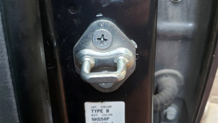
When the car door closes, one or the other of these types of latch firmly grips a headed pin or a U-shaped striker bar on the door pillar. Whether your car has a jaw or a rotary tooth-type latch, for our discussion here, we will simply use the term jaw.

When you open the car door by pulling the lever or door handle, the locking mechanism releases the jaw and the door opens. The jaw is then held in the unlocked position by the locking mechanism. When the door closes, the jaw hits the striker and is pushed back into the locked position.

Warning No. 1
If your car door refuses to close and lock properly, repeatedly attempting to close it can damage the locking mechanism. This can make a relatively inexpensive corrective action much more costly.
Warning No. 2
You might be tempted to hold the door closed with one hand and drive the car home or to a repair center. Never take this risk. You may have your seatbelt secured and feel safe, but you could lose your grip on that door. And if it opened, it could hit a passing car and cause a serious accident.

Reasons a Car Door Won’t Close All the Way

So, your car door closes but does not lock and can be opened. Or the door when closed simply bounces back open.

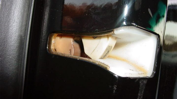
# 1 – Latch Jaw Stuck in Closed Position

car door won't latch

Examine the door latch that won’t close. Now examine another door that opens and closes properly. On that door, you will see what a fully open jaw looks like.

If the faulty door latch is not in the fully open position, the door will not close.

How to Fix

  1. While observing the jaw, use one hand to pull the lever or door handle as if to open the door. This should release the jaw and it should spring out into the fully open position. Release the door handle. The jaw should remain open.
  2. Using a screwdriver, try to push the jaw into the closed position. It should easily move to the closed position and “click” into place. Pull the lever or door handle again. The jaw should snap back into the open position again.
  3. Test the door’s operation. If it locks and reopens properly for three or four tries, you have solved your problem.
  4. If these steps do not resolve the issue, your car door’s locking mechanism may be faulty. Corrective action by a qualified technician will be necessary.

# 2 – Jaw Won’t Stay in Latched Position

Examine the offending door latch. If the jaw is in a position other than fully open, there may be a problem with the locking mechanism.

How to Fix

  1. Using a screwdriver, move the jaw into the fully open position. Then move it into the closed position. It should “click” into the closed position. Try to move it with the screwdriver. It should be held firmly in that position.
  2. While observing the jaw, pull the lever or door handle as if to open the door. This should release the jaw and it should snap into the open position. If it does not, the locking mechanism may have failed. It is also possible that the locking mechanism at the jaw is dry and sticking due to a lack of lubrication. Follow steps (3) and (4) to free and lubricate the jaw.
  3. You may need assistance for this step. Have your assistant hold the door opening lever or handle as if to open the door. Using a penetrating lubricant such as WD-40, lightly spray the jaw’s pivot point(s). Do not overspray. Work the jaw back and forth with the screwdriver until it moves freely. Release the door opening lever. Push the jaw into the closed position. Wipe away any sprayed lubricant.
  4. With the jaw in the closed position, pull the door opening lever. The jaw should snap into the open position. If it does not move or only moves partially to the open position, the locking mechanism may be faulty. Corrective action by a qualified technician will be necessary.

# 3 – Latch Jaw and Striker Misaligned

door striker

A sagging door can be the result of a prior minor collision which, in turn, causes the latch jaw not to align with the striker on the pillar. Alternatively, the hinge fasteners may have loosened, allowing the door to become misaligned.

How to Fix

Corrective action will require realigning the door. This can be a difficult process for a home DIY mechanic. In most cases, the car will need to be taken to a quality body shop for corrective measures.

# 4 – Frozen Latch Mechanism

In a modern car, a frozen door latch is a rare event. But it can happen.

Note: A frozen latch is only possible if the weather is extremely cold, i.e., well below freezing (32°F) and accompanied by rain, freezing rain, and/or snow.

Such an event can occur in this way:

Your car has been parked for some time outside during a storm. Precipitation accompanied by plummeting temperatures has frozen your windshield and windows. You open the door to grab your ice scraper and the door won’t close. The locking mechanism has frozen so that the jaw does not open fully or does not lock when the door is closed.

How to Fix

Three possible solutions here:

  1. First, do not slam the door. This could damage the latch jaw. Instead, with the door slightly open, pull the door opening lever or handle and let it snap several times. Often, the impact of this action will break a frozen locking mechanism. If that doesn’t work, then…
  2. Get in and start the car. Close the door as much as possible. Warm up the engine and turn the front windshield defroster to “high.” Set the heater temperature to its highest setting. This will warm the inside of the car, including the door assembly. Fifteen to twenty minutes may be needed to thaw the door locking mechanism. If this doesn’t solve the problem, there is another option…
  3. You will need warm water (at home, for example). Start the engine and defrost as described in step (2) above. While the car is warming up, fill a kettle with warm tap water (not boiling). When the car interior and the glass are fully warm, hold the door nearly closed. Now, slowly pour the warm water over the rear corner of the door above the exterior latch handle.
  4. Following each of the above procedures, close the door to see if you have solved the problem. If the door still does not lock, you will need to contact a service technician for corrective action.

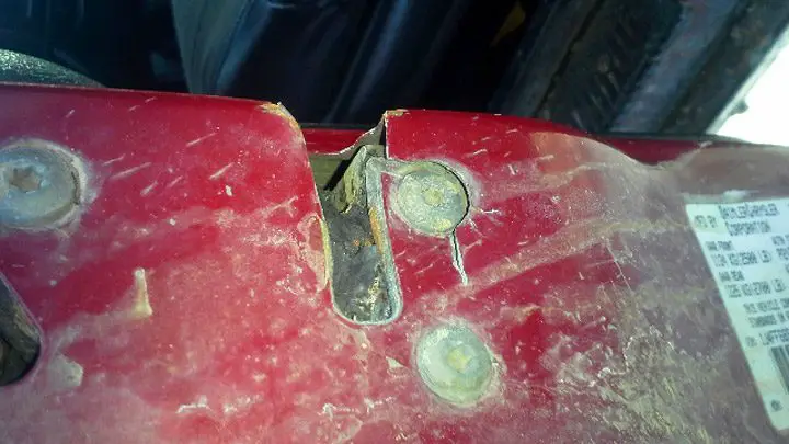
# 5 – Jaw Area Corroded

corroded door latch

With older vehicles (especially those stored outside for long periods), sufficient corrosion of the jaw area can prevent a car door from closing and locking.

How to Fix

A latch stuck due to severe corrosion may eventually be corrected by following steps (3) and (4) from the “Jaw Won’t Stay in Latched Position” section above, which deal with lubricating the jaw.

# 6 – Latch Mechanism Failure

A failure of the operational locking mechanism is very possible if none of the steps described above correct the problem.

How to Fix

If this is the case, repair or replacement of the locking mechanism by a qualified automotive technician will be necessary.