Citroën Revises Hybrid SUV Power Figures
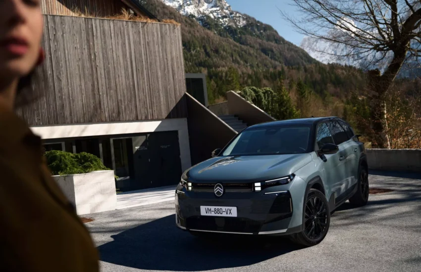
In a notable technical clarification, Citroën has officially updated the power rating for its C5 Aircross Hybrid plug-in model. The family SUV, a key model in the Stellantis lineup, now boasts a certified combined system output that exceeds its initial announcements, marking a significant revision in its specifications.
Understanding the Power Correction
The adjustment stems from a refined certification process for the complex hybrid powertrain. Modern plug-in hybrid systems combine an internal combustion engine with an electric motor, and their total power output is not always a simple sum. The revised figure reflects a more accurate measurement of the synchronous performance of both power sources, ensuring compliance with the latest WLTP testing protocols. This highlights the evolving nature of automotive engineering and the precision required in publishing technical data.

What the Update Means for Drivers
For potential owners and current drivers, this power revision is positive news. The enhanced power rating translates to more confident acceleration and improved responsiveness, particularly in hybrid mode where both engines work in tandem. It reinforces the C5 Aircross Hybrid’s positioning as a comfortable yet capable family vehicle, offering a compelling blend of electric-only range for daily commutes and extended flexibility for longer journeys without compromise on performance.
The Bigger Picture for Hybrid Vehicles
This event underscores a broader trend in the automotive industry. As hybrid and electric vehicle technology advances rapidly, precise power certification becomes increasingly complex. Manufacturers are continuously refining their testing methodologies to provide transparent and accurate data to consumers. The Citroën C5 Aircross Hybrid’s story serves as an example of this dynamic landscape, where specifications can be optimized even after a model’s initial launch, ultimately benefiting the end user with a more powerful and efficient driving experience.