O2 Oxygen Sensor

Oxygen Sensor Description and Related Information

So you want to know a little more about how an oxygen sensor works? Well, as you may already know, many sensors are needed for a modern engine to run, but none are arguably as important as the oxygen sensors. These sensors read the amount of unburned oxygen in the exhaust gases. The computer then uses this reading to balance the fuel mixture. As the oxygen content in the exhaust increases (known as a lean condition), the sensor voltage reading decreases. This signals the computer to increase the amount of fuel delivered by the injectors. In turn, the oxygen content in the exhaust gases decreases (known as a rich condition).

The oxygen sensor voltage increases due to this enrichment, and the computer responds by reducing the fuel flow. As the amount of fuel decreases, we return to a lean mixture and the sensor voltage drops. This process repeats as long as the engine is running. This continuous feedback loop is the heart of the fuel control system. Typical lean voltage readings are between 0 and 0.3 volts, and rich readings range from 0.6 to 1 volt. An ideal fuel mixture (14.7:1) will produce a voltage of about 0.5 volts.

So why not just maintain a constantly measured amount of fuel that varies with throttle position? Well, many factors affect the amount of fuel required to maintain a 14.7:1 ratio. Some of these factors include fuel quality, atmospheric pressure, humidity, and more. Hence the need for O2 sensors! The switching rates of sensors vary, but most modern sensors average at least half a dozen switches per second. Older sensors switched as slowly as once per second, so you can imagine the improvement in emissions produced by the new style sensors!
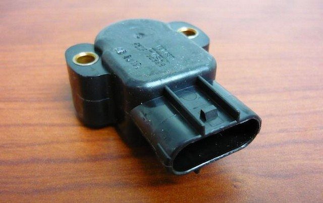
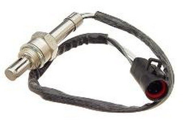
oxygen sensor

Old-style oxygen sensors used before 1982 were of the 1 or 2-wire unheated type. These sensors would not start recording a correct reading until the exhaust had heated the sensor to its operating range. This resulted in the computer operating in “open loop” (using predefined fuel values that actually make the engine run rich) for longer periods. All newer style sensors are “Heated Oxygen Sensors” (HO2S) that incorporate a heating element used to bring the sensor to operating temperature sooner, typically in less than a minute but as quickly as 10 seconds is possible! The heating elements also prevent the sensors from cooling when the engine is idling. These heated sensors are normally of 3 and 4-wire design.

There are a few different style sensors, which vary in chemical composition and design, but their purpose and function remain the same. The engineering behind these is beyond the scope of this page, but there are a few points to consider. Oxygen sensors compare the oxygen content of the outside air to the oxygen content of the exhaust gases. The outside air is brought into the sensor either through a vent in the sensor housing or through the wiring connector itself. Some types of sensors generate a voltage when the oxygen content of the exhaust changes and some have variable resistance. The newest style, heated wideband O2 sensors, have a voltage range between 2 and 5 volts. Despite all these differences and the actual readings produced by the sensors, the computer processes the information so that we have the expected readings of 0 to 1 volt. There are, of course, a few exceptions. Some heated Titania type O2 sensors can produce a voltage up to 5 volts. This reading is not altered by the computer. Another design of the same style sensor is configured to read values opposite to what you expect. High voltages indicate a lean mixture and low voltages a rich mixture. These 2 types of oxygen sensors are not common and have been used mainly on a few Nissan, Jeep, and Eagle applications. There always has to be an exception! Engineers, yeah I know!

You will also notice that on most post-1996 applications, there is a second set of oxygen sensors beyond the catalytic converters. These operate in the same way as the front O2 sensors, but their readings are used differently, and their purpose is to measure the efficiency of the converters, not to monitor the engine’s fuel ratios. Please refer to our article on oxygen sensor codes for diagnostic help and a more detailed description of O2 monitors. This article provides diagnostic assistance and valuable testing procedures as well as the likely causes of rich or lean oxygen sensor codes. I hope you found this information helpful!

TPS Sensor – Throttle Position Sensor

Throttle Position Sensor Description and Related Information

Almost all post-96 vehicles use a throttle position sensor (TPS) to inform the engine control module of the accelerator pedal and throttle plate position. TPS sensors are normally mounted on the throttle body with the throttle plate shaft running through the sensor. When the accelerator pedal is pressed, the throttle plate opens, rotating the sensor’s internal variable resistance. As the throttle opens, the voltage returned to the computer by the throttle position sensor varies (typically increasing), signaling the throttle opening rate as well as the throttle position. The computer uses this information to adjust fuel compensation, which is the duration the injectors remain open, providing more fuel.

Most throttle position sensors have at least 3 wires. These are for a 5-volt reference, a ground line, and the actual TPS voltage line. When testing the throttle position sensor system, always ensure you have the 5-volt reference and ground, then monitor the signal line for the actual throttle position sensor voltage output.

You can monitor this by probing the circuit again at the TPS. The voltage should increase steadily as the throttle is opened. This should be checked with the ignition on and the engine off. Use an appropriate wiring diagram and always verify the correct base voltage before scanning the accelerator pedal. Any voltage drop or irregular voltage indicates a problem. You should also check by tapping and heating the sensor if you suspect a possible intermittent issue. Refer to our article on automotive circuit testing for more help with these tests, and always exercise caution.

throttle position sensor

Possible symptoms of a faulty TP sensor include hesitation or stumbling during acceleration or surging, a dead spot in the throttle, rough idle, or a check engine light with associated codes. Some older style throttle position sensors are adjustable, but most newer style sensors are fixed position. Base TPS voltage readings are essential for proper fuel compensation operation, so always use your scan tool or multimeter to verify proper adjustment. A poorly secured sensor will cause erratic symptoms, including rough idle and hesitation, so check this as well. Have other questions? Use the Get Help link and we’ll assist you! Thank you for visiting and be sure to check out some of our highly informative articles regarding engine light repair!

If you find you need a replacement TP sensor, please visit one of our suggested parts suppliers. We search for the best companies for value and service and only recommend the best. You won’t find better prices anywhere and you can buy with confidence from reputable merchants! Thank you for visiting and have a great day!

Vehicle Speed Sensor VSS

🚗 Vehicle Speed Sensor (VSS): Complete Guide


📌 VSS Function

The Vehicle Speed Sensor (VSS) measures the speed of the wheels or transmission and transmits this data to various systems:

  • Power Steering: Adjusts pressure to facilitate maneuvering at low speeds.
  • ABS: Detects wheel lock-up.
  • Transmission: Optimizes gear shifts.
  • Cruise Control: Maintains a constant speed.
  • Air Suspension: Adjusts ride height at high speeds.
  • Speedometer: Displays real-time speed.

⚠️ Symptoms of a Faulty VSS

  • 🚨 Inactive or erratic speedometer.
  • 🔄 Transmission issues: Jerky or delayed gear shifts.
  • 🛑 ABS/ESP failure: ABS light on, loss of stability.
  • 🚫 Cruise control inoperative.
  • 🏎️ Stiff power steering at low speeds.

🔍 Common Causes

  1. Damaged wiring: Cut wires, corrosion, oxidized connectors.
  2. Faulty VSS: Contaminated magnet, internal wear.
  3. Damaged trigger wheel (in the differential or transmission).
  4. Water intrusion in connectors.
  5. Multiplexing issues: Data not shared between modules.

🔧 VSS Diagnosis

1. Using a diagnostic tool

  • 📊 Check live data (vehicle speed, related codes: P0500, P0501).
  • 🔄 Compare values with other sensors (e.g., ABS wheel sensors).

2. Manual tests

  • Measure the resistance of the VSS (refer to manufacturer specifications).
  • 🔍 Visual inspection:
  • Check connectors (corrosion, oxidation).
  • Inspect the trigger wheel (debris, broken teeth).
  • Look for metal particles on the sensor magnet.

3. Circuit verification

  • 🔌 Test the circuit power and ground with a multimeter.
  • 🔄 Ensure you test the correct sensor (some vehicles have multiple VSS).

🛠️ Recommended Repairs

  • Replace the VSS if resistance is out of specification.
  • Repair wiring: Soldering, replacing connectors.
  • Clean the trigger wheel and sensor (magnetic decontamination).
  • Update modules (PCM, ABS) if necessary.

🚨 Key Points to Remember

  • Do not replace the VSS without first checking the wiring and connectors.
  • Consult Technical Service Bulletins (TSB) for recurring issues on your model.
  • Use original parts to ensure signal compatibility.

💡 Pro Tip:
If in doubt, use an oscilloscope to analyze the VSS signal and detect interruptions or waveform anomalies.

📞 Need help? Share your vehicle’s make and model for specific advice! 🚗🔧

Idle Control Valve / Stepper Motor IAC

Idle Control Valve / Stepper Motor


1. What is the idle control valve / stepper motor and what is its function in the car?

The idle speed control (ISC) valve, also called the idle air control (IAC) valve, is used in fuel-injected engines to control idle speed. The stepper motor, a type of idle valve, consists of a pintle that blocks or allows air to bypass the throttle plate. The powertrain control module (PCM) regulates the operation of the stepper motor.

2. What are the symptoms of a faulty IAC / stepper motor?

Unsurprisingly, a faulty IAC often results in engine idle problems. An engine idling too fast or too slow may indicate a defective IAC. An engine that stalls can also indicate IAC issues.

3. How can I check if my IAC / stepper motor is faulty?

Most of the time, if there is a problem with the IAC or its control circuit, the PCM will set a diagnostic trouble code (DTC) and illuminate the “Check Engine” light (CEL). If the light is on, you can connect a diagnostic tool to the designated port under the dashboard and read the listed error codes. If the code indicates a problem with the IAC or its circuits, the vehicle-specific repair manual should be consulted before proceeding with further tests.

4. How do I change the IAC / stepper motor in my car?

The method for replacing the IAC varies from vehicle to vehicle, but it is fairly straightforward in most cases. Specific repair information should be consulted before you replace your IAC. A typical IAC replacement proceeds as follows:

  • Disconnect the negative battery terminal

  • Disconnect the IAC electrical connector

  • Remove the IAC valve mounting screws

  • Remove the IAC assembly

  • Reinstall in the reverse order of disassembly

Lambda probe (oxygen sensor)

The Lambda Sensor (Oxygen Sensor)

1. What is a Lambda Sensor and What is its Purpose?

The lambda sensor, or oxygen sensor, measures the oxygen content in the exhaust gases. This information is sent to the Powertrain Control Module (PCM) to optimize engine parameters:

  • Upstream Sensor: Regulates the air/fuel mixture for efficient combustion.
  • Downstream Sensor: Monitors the efficiency of the catalytic converter.

2. What are the Symptoms of a Faulty Lambda Sensor?

A faulty lambda sensor can cause:

  • Increased fuel consumption.
  • Higher pollutant emissions.
  • Illumination of the “Check Engine” light (CEL).
  • Reduced engine power and responsiveness.
  • Irregular engine operation and unstable idle.

3. How to Check if the Lambda Sensor is Faulty?

  • If the CEL is on, use a diagnostic tool to read the error codes.
  • Functional sensors behave as follows:
    • Upstream Sensor: Produces a fast sine wave (0.1V to 0.9V at idle).
    • Downstream Sensor: Displays a stable voltage (around 0.45V) if the catalytic converter is in good condition.
  • An oscilloscope or scanner can confirm sensor responsiveness.
    Always refer to your vehicle’s specific manual for detailed testing procedures.

4. How to Replace a Lambda Sensor?

Here are the general steps to replace a lambda sensor:

  1. Disconnect the negative battery cable.
  2. Unplug the sensor’s electrical connector.
  3. Remove the sensor using a suitable wrench or special socket.
  4. Install the new sensor in reverse order.

Before proceeding, consult the instructions specific to your vehicle model.

Throttle Position Sensor / Throttle Potentiometer

Throttle Position Sensor / Throttle Potentiometer


1. What is a throttle position sensor and what is its function in the car?

Latest fuel injection engine models use a throttle position sensor (TPS) to inform the powertrain control module (PCM) about the throttle opening rate and its position. The PCM then uses this information to control many output data such as fuel control.

2. What are the symptoms of a faulty throttle position sensor?

A faulty TPS can create many problems, the most common being hesitation or misfires during acceleration. Normally, the Check Engine Light (CEL) is also illuminated. Other symptoms may include (non-exhaustive list): changes in power and response, increased emissions, irregular engine operation, and poor idle quality.

3. How can I check if my throttle position sensor is broken?

Generally, if there is a problem with the TPS or its circuits, a diagnostic trouble code (DTC) will be recorded and the Check Engine Light (CEL) will illuminate. If the light is on, you can plug a diagnostic tool into the designated port under the dashboard and read the error codes listed. If the code indicates a problem with the TPS or its circuits, the vehicle-specific repair manual should be consulted before proceeding with further tests.

4. How do I change the throttle position sensor?

The method for replacing a TPS varies from vehicle to vehicle, but it is quite simple in most cases. Specific repair information should be consulted before you replace your TPS. A typical TPS replacement proceeds as follows:

  • Disconnect the negative terminal of the battery.

  • Disconnect the electrical connector from the TPS.

  • Remove the TPS mounting screws.

  • Remove the TPS.

  • Reinstall in the reverse order of removal.

  • Adjust the TPS if necessary.

Honda B-CAN and F-CAN

Body Controller Area Network (B-CAN) and Fast Controller Area Network (F-CAN)

The Body Controller Area Network (B-CAN) and the Fast Controller Area Network share information between multiple Electronic Control Units (ECUs). B-CAN communication operates at a slower speed (33.33 kbps) for convenience-related items and other functions. F-CAN information moves at a faster speed (500 kbps) for “real-time” functions such as fuel and emissions data. To allow both systems to share information, the gauge control module translates information from B-CAN to F-CAN and from F-CAN to B-CAN. This is called the gateway function.

DTC 11-11: Right front wheel speed sensor circuit malfunction
DTC 11-12: Right front wheel speed sensor power source malfunction
DTC 12-11: Right front wheel speed sensor electrical noise or intermittent interruption
DTC 12-12: Right front wheel speed sensor short to other sensor circuit
DTC 12-120: Right front wheel speed sensor circuit malfunction
DTC 12-13: Right front wheel speed sensor installation error
DTC 12-14: Right front wheel speed sensor installation error
DTC 12-15: Right front wheel speed sensor installation error
DTC 13-11: Left front wheel speed sensor circuit malfunction
DTC 13-12: Left front wheel speed sensor power source malfunction
DTC 14-11: Left front wheel speed sensor electrical noise or intermittent interruption
DTC 14-12: Left front wheel speed sensor short to other sensor circuit
DTC 14-120: Left front wheel speed sensor circuit malfunction
DTC 14-13: Left front wheel speed sensor installation error
DTC 14-14: Left front wheel speed sensor installation error
DTC 14-15: Left front wheel speed sensor installation error
DTC 15-11: Right rear wheel speed sensor circuit malfunction
DTC 15-12: Right rear wheel speed sensor power source malfunction
DTC 16-11: Right rear wheel speed sensor electrical noise or intermittent interruption
DTC 16-12: Right rear wheel speed sensor short to other sensor circuit
DTC 16-120: Right rear wheel speed sensor circuit malfunction
DTC 16-13: Right rear wheel speed sensor installation error
DTC 16-14: Right rear wheel speed sensor installation error
DTC 16-15: Right rear wheel speed sensor installation error
DTC 17-11: Left rear wheel speed sensor circuit malfunction
DTC 17-12: Left rear wheel speed sensor power source malfunction
DTC 18-11: Left rear wheel speed sensor electrical noise or intermittent interruption
DTC 18-12: Left rear wheel speed sensor short to other sensor circuit
DTC 18-120: Left rear wheel speed sensor circuit malfunction
DTC 18-13: Left rear wheel speed sensor installation error
DTC 18-14: Left rear wheel speed sensor installation error
DTC 18-15: Left rear wheel speed sensor installation error
DTC 21-11: Right front magnetic encoder malfunction (missing pulse)
DTC 22-11: Left front magnetic encoder malfunction (missing pulse)
DTC 23-11: Right rear magnetic encoder malfunction (missing pulse)
DTC 24-11: Left rear magnetic encoder malfunction (missing pulse)
DTC 25-11: Yaw rate sensor internal circuit malfunction
DTC 25-12: Yaw rate sensor stuck
DTC 25-13: Yaw rate sensor output signal malfunction
DTC 26-11: Lateral acceleration sensor internal circuit malfunction
DTC 26-12: Lateral acceleration sensor stuck
DTC 26-13: Lateral acceleration sensor output signal malfunction
DTC 27-11: Steering angle sensor internal circuit malfunction
DTC 27-12: Steering angle sensor stuck
DTC 27-13: Steering angle sensor output signal malfunction
DTC 27-14: Steering angle sensor counter malfunction
DTC 31-11: ABS solenoid valve malfunction
DTC 32-11: ABS solenoid valve malfunction
DTC 33-11: ABS solenoid valve malfunction
DTC 34-11: ABS solenoid valve malfunction
DTC 35-11: ABS solenoid valve malfunction
DTC 36-11: ABS solenoid valve malfunction
DTC 37-11: ABS solenoid valve malfunction
DTC 38-11: ABS solenoid valve malfunction
DTC 41-11: Right front wheel lock
DTC 42-11: Left front wheel lock
DTC 43-11: Right rear wheel lock
DTC 44-11: Left rear wheel lock
DTC 51-11: Motor malfunction
DTC 51-12: Motor drive circuit malfunction
DTC 52-11: Motor stuck OFF
DTC 53-11: Motor relay stuck ON
DTC 54-11: Safety relay stuck ON
DTC 54-12: Safety relay stuck OFF
DTC 56-11: Safety relay power source malfunction
DTC 61-11: VSA modulator-control unit power source (IG) circuit low voltage
DTC 62-11: Modulator-control unit power source (IG) circuit high voltage
DTC 64-11: Sensor power source circuit low voltage
DTC 64-12: Sensor power source circuit high voltage
DTC 65-11: Brake fluid level switch circuit malfunction
DTC 66-11: Pressure sensor circuit malfunction
DTC 66-13: Pressure sensor malfunction
DTC 68-11: Brake pedal position switch stuck
DTC 68-12: Brake pedal position switch stuck ON
DTC 71-11: Different diameter tire malfunction (right front or left rear)
DTC 71-12: Different diameter tire malfunction (left front or right rear)
DTC 71-13: Different diameter tire malfunction (right front and right rear)
DTC 71-14: Different diameter tire malfunction (left front and left rear)
DTC 71-15: Different diameter tire malfunction (right front and left front)
DTC 71-16: Different diameter tire malfunction (right rear and left rear)
DTC 81-11: Modulator-control unit internal circuit malfunction
DTC 81-12: Modulator-control unit internal circuit malfunction
DTC 81-13: Modulator-control unit internal circuit malfunction
DTC 81-14: Modulator-control unit internal circuit malfunction
DTC 83-11: PCM (engine) malfunction
DTC 83-12: PCM (A/T) malfunction
DTC 84-12: Steering angle sensor neutral position memorization incomplete
DTC 86-11: F-CAN bus failure
DTC 86-12: F-CAN communication with PCM (engine) malfunction
DTC 86-13: F-CAN communication with PCM (A/T) malfunction
DTC 86-14: F-CAN communication with gauge control module malfunction
DTC 86-15: F-CAN communication with yaw acceleration sensor malfunction
DTC 104-11: Yaw acceleration sensor internal circuit malfunction
DTC 104-12: Yaw acceleration sensor power source malfunction
DTC 104-13: Yaw acceleration sensor internal circuit malfunction
DTC 108-11: Steering angle sensor stuck
DTC 121-11: VSA solenoid valve malfunction
DTC 122-11: VSA solenoid valve malfunction
DTC 123-11: VSA solenoid valve malfunction
DTC 124-11: VSA solenoid valve malfunction
DTC 158-01: ECU software update failure

What is ECM?

The electronic control module (ECM) or engine control module (ECM), also known as the powertrain control module (PCM), is a computer that manages the engine’s ignition, fuel injection, and emission systems. In some vehicles, it may also control the operation of transmission and anti-lock braking systems.

How to Check Fuses?

There are several methods to check the fuses in your car:

  1. Visual inspection
  2. Testing with a multimeter
  3. Using a circuit tester

Visual inspection

Inspect a fuse in your car to check the continuity of its fuse element. So, if the inner connector has melted, you need to replace the fuse. However, sometimes the wire may appear intact even in a blown fuse.

Testing with a multimeter

First, it is necessary to set your tester to continuity mode (the icon usually looks like a sound wave). Then, touch the two contact terminals of the fuse with the multimeter probes. If the circuit is good, the tester beeps.

Using a circuit tester

The circuit tester is a voltage tester or a lamp connected to wires. To check your fuse, you need to activate a faulty circuit. First, connect the wire of one probe to the (-) terminal of the battery. Then, touch one of the fuse contacts with the wire of the second probe. Repeat this action with the second contact terminal. If one fuse terminal has voltage and the other does not, it means the fuse element has melted.

The Renault Fault Code List in DF

The RENAULT Manufacturer Fault Code List

DF001 0115 Coolant temperature sensor circuit
DF002 0110 Air temperature sensor circuit
DF004 012A Boost pressure sensor circuit
DF007 0190 Rail pressure sensor circuit
DF011 0641 Sensor supply voltage No. 1
DF012 0651 Sensor supply voltage No. 2
DF013 0697 Sensor supply voltage No. 3
DF015 0657 Main relay control circuit
DF025 0380 Preheating unit diagnostic link
DF026 0201 Cylinder 1 injector control circuit
DF027 0202 Cylinder 2 injector control circuit
DF028 0203 Cylinder 3 injector control circuit
DF029 0204 Cylinder 4 injector control circuit
DF032 1641 Heater relay 1 control circuit
DF033 1642 Heater relay 2 control circuit
DF034 1643 Heater relay 3 control circuit
DF038 0606 ECU
DF047 0560 ECU supply voltage
DF050 0571 Brake switch circuit
DF051 0564 Cruise control / speed limiter function
DF052 0200 Injectors control circuit
DF053 0089 Rail pressure regulation function
DF054 0045 Turbocharging solenoid valve control circuit
DF056 0100 Air flow sensor circuit
DF090 0500 Vehicle speed sensor circuit
DF098 0180 Fuel temperature sensor circuit
DF101 C121 Multiplexed trajectory control link
DF120 0335 Engine speed sensor signal
DF195 0016 Camshaft sensor / engine speed consistency
DF200 2226 Atmospheric pressure sensor
DF201 0101 Air flow sensor information
DF209 0409 EGR valve position sensor circuit
DF272 0487 EGR valve control circuit
DF293 2264 Water in diesel fuel detector
DF297 2002 Particulate filter
DF304 245A EGR bypass circuit
DF310 1544 Temperature sensor upstream of particulate filter
DF319 0340 Camshaft sensor circuit
DF323 2119 Air intake flap
DF342 0650 MIL warning light circuit
DF374 060B ECU
DF394 0420 Functional catalyst failure
DF409 0461 Fuel level sensor circuit
DF532 2502 Alternator load information
DF559 0480 Low speed cooling fan relay control
DF567 160C ECU
DF569 2263 Boost circuit
DF619 0402 EGR valve stuck open
DF631 0703 Brake switch information
DF641 2100 Air intake flap circuit
DF644 0001 Fuel flow regulator circuit
DF645 0638 Air intake flap position regulation
DF646 0120 Air intake flap position sensor
DF647 0488 EGR valve position regulation
DF648 060A ECU
DF651 0470 Turbine upstream pressure sensor circuit
DF652 0544 Turbine upstream temperature sensor circuit
DF653 0263 Cylinder No. 1 fuel injection calibration
DF654 0266 Cylinder No. 2 fuel injection calibration
DF655 0269 Cylinder No. 3 fuel injection calibration
DF656 0272 Cylinder No. 4 fuel injection calibration
DF721 0217 Engine overheating
DF771 0002 Adaptive flow regulation
DF778 2080 Turbine upstream temperature regulation
DF885 0087 Rail pressure
DF887 0226 Brake/accelerator pedal position
DF897 0090 Pump pressure regulator circuit
DF974 0225 Pedal potentiometer track 1 circuit
DF975 2120 Pedal potentiometer track 2 circuit
DF987 0575 Cruise control / speed limiter buttons
DF991 1205 Particulate filter injector control circuit
DF992 1644 Heater relay 1 control
DF993 1645 Heater relay 2 control
DF994 1646 Heater relay 3 control
DF997 1650 Heaters control unit link
DF998 0471 Turbine inlet pressure
DF1001 1545 Particulate filter upstream temperature regulation
DF1012 1525 Multiplexed information consistency for CC/SL
DF1013 0525 Cruise control inputs monitoring
DF1014 0574 Vehicle speed consistency
DF1015 0504 Brake contact information consistency
DF1016 0833 Clutch contact information consistency
DF1017 061A ECU
DF1018 062B ECU
DF1020 253F Engine oil dilution
DF1063 C415 Multiplexed trajectory control link
DF1068 0530 Refrigerant fluid pressure sensor voltage
DF1089 012B Boost pressure consistency
DF1195 047A Particulate filter relative pressure sensor circuit
DF1196 047B Particulate filter relative pressure sensor
DF1237 0403 EGR valve control circuit
DF1252 1632 Particulate filter solenoid injector circuit
DF1331 2503 System voltage – low
DF1334 2031 Catalyst upstream temperature sensor circuit
DF1355 1656 Multiplexed torque regulator link

DF00 10115 Coolant temperature sensor circuit
DF002 0110 Air temperature sensor circuit
DF004 012A Boost pressure sensor circuit
DF007 0190 Rail pressure sensor circuit
DF011 0641 Voltage supply; one of the sensors
DF012 0651 Voltage Power; 2 sensors
DF013 0697 Voltage; 3 sensors
DF015 0657 Main relay control circuit
DF025 0380 Preheating unit diagnostic connection
DF026 0201 Cylinder 1 injector control circuit
DF027 0202 Injector control circuit cylinder 2
DF028 0203 Cylinder 3 injector control circuit
DF029 0204 Injector control circuit cylinder 4
DF032 1641 Relay control circuit heater 1
DF033 1642 Heater relay control circuit 2
DF034 1643 Heater relay control circuit 3
DF038 0606 Calculator
DF047 0560 Computer supply voltage
DF050 0571 Brake Switch Circuit
DF051 0564 Controller Function / speed limiter
DF052 Injectors control circuit 0200
DF053 0089 Rail pressure regulation function
DF054 0045 Turbocharging solenoid control circuit
DF056 0100 Air flow sensor circuit
DF090 0500 Vehicle speed sensor circuit
DF098 0180 Fuel temperature sensor circuit
DF101 C121 Multiplexed trajectory control Link
DF120 0335 Engine speed sensor signal
DF195 0016 Consistency cam shaft sensor / engine speed
DF200 2226 Atmospheric pressure sensor
DF201 0101 Information air flow sensor
DF209 0409 EGR valve position sensor circuit
DF272 0487 EGR valve control circuit
DF293 2264 Detector of water in diesel fuel
DF297 2002 Particle filter
DF304 245A Circuit bypass EGR
DF310 1544 Temp Sensor. * Upstream particulate filter
DF319 0340 Cam shaft sensor circuit
DF323 2119 Air intake damper
DF342 0650 MIL control circuit
DF374 060B Calculator
DF394 0420 Failure Functional Catalyst
DF409 0461 Fuel level sensor circuit
DF532 2502 Alternator charges Information
DF559 0480 Small speed fan control relay
DF567 160C Calculator
DF569 2263 Boost Circuit
DF619 EGR valve open blocked 0402
DF631 0703 Information brake switch
DF641 2100 Circuit of the air intake flap
DF644 0001 Circuit fuel flow regulator
DF645 0638 Regulation position of the air inlet flap
DF646 0120 Position sensor air damper on admission
DF647 0488 Position control of the EGR valve
DF648 060A Calculator
DF651 0470 Turbine upstream pressure sensor circuit
DF652 0544 Turbine upstream temperature sensor circuit
DF653 0263 Cylinder fuel injection calibration; 1
DF654 0266 Cylinder fuel injection Calibration; 2
DF655 0269 Cylinder fuel injection Calibration; 3
DF656 0272 Cylinder fuel injection Calibration; 4
DF721 0217 Motor overtemperature
DF771 0002 Adaptive flow control
DF778 2080 Turbine upstream temperature control
DF885 0087 Rail pressure
DF887 0226 Brake Pedal Position/ accelerator
DF897 0090 Circuit pump pressure regulator
DF974 0225 Pedal potentiometer circuit track 1
DF975 2120 Pedal potentiometer circuit track 2
DF987 0575 Keys cruise control / speed limiter
DF991 1205 Control circuit particle filter injector
DF992 1644 Heater relay control 1
DF993 1645 Relay control heater 2
DF994 1646 Heater relay control 3
DF997 1650 Control box connection Heaters
DF998 0471 Turbine inlet pressure
DF1001 1545 Upstream temperature control particle filter
DF1012 1525 Coherences information multiplexed for RV / LV
DF1013 0525 Monitoring cruise control inputs
DF1014 0574 Consistency vehicle speed
DF1015 0504 Brake Contact Information Consistency
DF1016 0833 Consistency clutch Contact Information
DF1017 061A Calculator
DF1018 062B Calculator
DF1020 253F Engine oil dilution
DF1063 C415 Multiplexed trajectory control Link
DF1068 0530 Fluid pressure sensor voltage for cooling. **
DF1089 012B Boost pressure Consistency
DF1195 047A Circuit Capt. * Relative pressure particulate filter
DF1196 047B Relative pressure sensor particulate filter
DF1237 0403 EGR valve control circuit
DF1252 1632 Particulate filter circuit solenoid injector
DF1331 2503 System voltage – Low
DF1334 2031 Catalyst upstream temperature sensor circuit
DF1355 1656 TCU Multiplex connection

 
DTC Code Description
DF00 Injection – Coolant temperature sensor circuit.
DF001 Injection – Coolant temperature sensor circuit
ABS – Computer supply
Climate – Computer
Headlights – Computer
Discharge bulb – Computer
Multimedia – Computer
UCH – UCH
Airbag/pretensioners – Computer
DF002 Injection – Air temperature sensor circuit
Transmission – Computer
Steering – Computer
Headlights – Front height sensor circuit
Central Interior Unit – Steering lock
Parking – Left exterior sensor
Engine compartment interconnection unit – High speed fan relay control circuit
Airbag/pretensioners – Computer supply voltage
DF003 Transmission – Analog sensor supply
Headlights – Rear height sensor circuit
Central Interior Unit – Clutch switch circuit
Parking – Left interior sensor
DF004 Injection – Boost pressure sensor circuit
Headlights – Vehicle speed signal
Central Interior Unit – Brake switch circuit
Parking – Right exterior sensor
DF005 Transmission – Oil pressure sensor circuit
Headlights – Computer initialization
UCH – Card
Parking – Right interior sensor
Engine compartment connection unit – Internal electronic fault
DF006 ABS – Front left wheel speed sensor circuit
UCH – Front left wheel sensor
Parking – Audible warning
Engine compartment connection unit – Computer
DF007 Injection – Rail pressure sensor circuit
ABS – Rear left wheel speed sensor circuit
Climate – Interior temperature sensor circuit
Instrument panel – Fuel sensor circuit
UCH – Front right wheel sensor
Parking – Sensor supply voltage
Engine compartment connection unit – UPC – ALTERNATOR CONNECTION
DF008 Transmission – Multifunction switch intermediate position
Discharge bulb – Front height sensor circuit
UCH – Rear right wheel sensor
Parking – Computer fault
DF009 Transmission – Multifunction switch prohibited position
Headlights – Left adjustment motor circuit
Discharge bulb – Rear height sensor circuit
UCH – Rear left wheel sensor
Engine compartment connection unit – Ignition circuit
DF010 Injection – EGR valve position sensor circuit
Transmission – Instrument panel connection
Climate – Blending motor circuit
Headlights – Right adjustment motor circuit
Central Interior Unit – Steering column computer circuit
Airbag/pretensioners – Malfunction indicator light circuit
DF011 Injection – Sensor supply voltage No. 1
UCH – Rain/light sensor circuit
DF012 Injection – Sensor supply voltage No. 2
Transmission – Solenoid valve supply
Climate – Distribution motor circuit
UCH – Right turn signal circuit
Parking – Parking proximity sensor switch light
Engine compartment connection unit – ALTERNATOR
DF013 Injection – Sensor supply voltage No. 3
Headlights – Computer supply voltage
Discharge bulb – Vehicle speed signal
UCH – Left turn signal circuit
Engine compartment connection unit – VOLTAGE REGULATION
DF014 Injection – Vehicle speed information circuit
Headlights – Computer configuration
UCH – Card reader circuit
Engine compartment connection unit – LEFT SIDE LIGHTING CIRCUIT
DF015 UCH – Optical sensor circuit
Engine compartment connection unit – RIGHT SIDE LIGHTING CIRCUIT
DF016 Injection – EGR control circuit
Transmission – Locking solenoid valve circuit
Instrument panel – Oil level sensor circuit
UCH – At least 2 identical codes in summer set
Engine compartment connection unit – LEFT HEADLIGHT CIRCUIT
DF017 Injection – Pre/post-heating unit control circuit
Transmission – Heat exchanger flow solenoid valve circuit
ABS – Computer
UCH – At least 2 identical codes in winter set
Engine compartment connection unit – RIGHT HEADLIGHT CIRCUIT
DF018 Injection – Low speed cooling fan control circuit
Transmission – Locking slip
Discharge bulb – Actuators
Instrument panel – Instrument panel
UCH – Summer set 4 code programming not performed
Engine compartment connection unit – LEFT HIGH BEAM CIRCUIT
DF019 Injection – High speed cooling fan control circuit
Instrument panel – Battery voltage
UCH – Winter set 4 code programming not performed
Engine compartment connection unit – RIGHT HEADLIGHT CIRCUIT
DF020 Transmission – Old oil
Steering – Computer supply
ABS – Tachometric index programming
Discharge bulb – Power supply unit
UCH – Front internal antenna circuit
Engine compartment connection unit – FRONT FOG LIGHT CIRCUIT
DF021 Climate – Recirculation motor circuit
Multimedia – Computer configuration
UCH – Rear internal antenna circuit
Engine compartment connection unit – REVERSE LIGHT(S) CIRCUIT
DF022 UCH – Central internal antenna circuit
Engine compartment connection unit – REAR SCREEN DEFROSTING CIRCUIT
DF023 In