What does it mean?
This is a generic diagnostic trouble code (DTC) and applies to OBD-II vehicles. This may include, but is not limited to, vehicles from Ford, Chevrolet, Dodge, Ram, etc. Although generic, the exact repair steps may vary depending on the year, make, model, and powertrain configuration.
Essentially, the air conditioning evaporator works in the opposite way as a condenser. The condenser converts gas into fluid, and the evaporator converts fluid into gas while absorbing heat from the fan air passing through it during the process.
Its purpose is to remove heat from the air inside the cabin, thereby reducing the temperature inside the car. The functionality of the A/C evaporator temperature sensor is crucial for the proper operation of your HVAC (heating, ventilation, and air conditioning) system. The ECM (Engine Control Module) uses the electrical values from this sensor to adjust the interior temperature according to your needs, in coordination with your evaporator among other A/C components.
The ECM triggers P0538 and related codes (P0535, P0536, P0537, and P0539) when it detects a condition outside the desired electrical range in the A/C evaporator temperature sensor or its circuits. This could also be a mechanical or electrical issue. Always keep in mind the sensor’s environment (any sensor, for that matter), as it might be subjected to an environment with unique problems.
P0538 High Circuit in the A/C Evaporator Temperature Sensor is set when the ECM detects an unexpected high electrical condition in the A/C evaporator temperature sensor or its circuits.
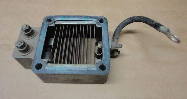
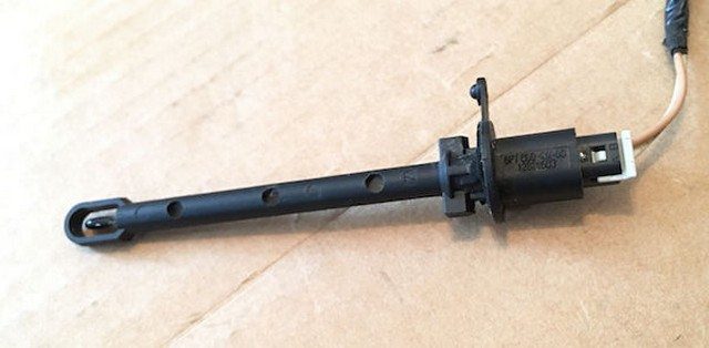
Photo of an evaporator temperature sensor style:
How severe is this DTC?
Since your entire HVAC system was designed with the sole purpose of keeping humans more comfortable, the severity here is set at the lowest possible level. A complete HVAC system malfunction would pose virtually no threat to your safety. That being said, if you value comfort like I do, you’ll need to address this issue immediately.
What are some of the symptoms of the code?
Symptoms of a P0538 trouble code may include:
No cold air blown from the vents
Erratic/fluctuating fan air temperature
A/C compressor clutch not engaging
HVAC system not operating as desired
What are some common causes of the code?
Causes
of this P0538 code may include:
Faulty or damaged A/C evaporator core
Faulty A/C evaporator temperature sensor
Faulty ECM (Engine Control Module)
Wiring issue in the sensor circuit
Wiring harness connector problem
Intermittent electrical connection
Internal resistance (corrosion, damaged harness, overheated circuit, etc.)
What are the troubleshooting steps for P0538?
Make sure to check the Technical Service Bulletins (TSBs) for your vehicle. Access to a known fix can save you time and money during diagnosis.
Basic Step #1
Locate and visually inspect the A/C evaporator temperature sensor. Generally, the evaporator core is located inside the HVAC air box (heating, ventilation, and air conditioning). The A/C evaporator temperature sensor is usually mounted on the evaporator itself or very close to it. You may be able to access it by looking under the dashboard fairly easily. It’s also possible that you’ll need to remove many plastic panels and/or the radio, so always refer to your service manual for the specific location. Keep an eye out for any signs of overheating and/or corrosion on the sensor itself. This could indicate your problem. If it proves faulty, replace the sensor.
TIP: Ensure your interior is at a reasonable temperature. Start prying on cold plastic and it will break, so be careful.
Basic Step #2
Test the temperature sensor. Most of the time, these sensors are resistance-type sensors. In other words, the resistance inside the sensor changes in direct relation to the temperature. Understanding how this works probably gives you an idea of how to diagnose the sensor itself. Usually, the manufacturer will have a desired resistance at certain temperatures. Using your multimeter, you can record the resistance in the sensor and compare it to the desired values specified by your manufacturer. If an open is present, you may have internal resistance in the sensor itself and it will need to be replaced.
NOTE: Your manufacturer may have a specific diagnostic strategy depending on the sensor type, make, model, etc., so always refer to your service manual. If you are not comfortable with electrical testing and/or working around refrigeration systems, take your vehicle to a reputable shop.
Basic Step #3
Check the wiring. Given the location of the evaporator temperature sensor, it may be easy to locate and trace the harness to check for any obvious signs of damage. Especially where the driver’s and passengers’ feet might interfere with the wiring (if possible).