What does it mean?
This is a generic diagnostic trouble code (DTC) and applies to many OBD-II vehicles (1996-newer). This may include, but is not limited to, vehicles from Ford, Lincoln, Chevrolet, GMC, Dodge, etc. Although generic, the exact repair steps may vary depending on the year, make, model, and powertrain configuration.
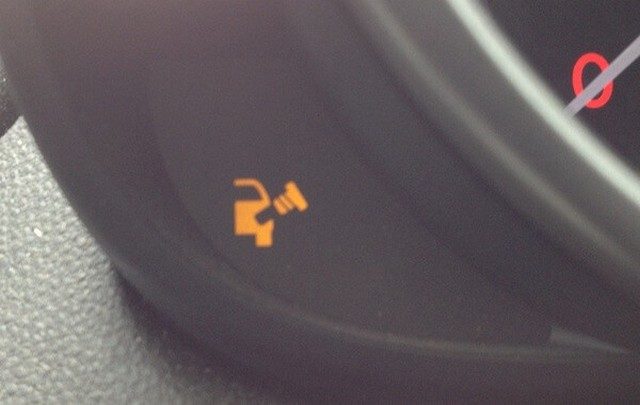
A stored P0623 code means that the Powertrain Control Module (PCM) has detected a malfunction in the generator lamp control circuit.
The generator lamp is located in the dashboard. Its main purpose is to warn the driver of potential charging system problems when it is illuminated.
The PCM typically monitors the continuity of the generator lamp control circuit whenever the engine is running. The generator lamp control circuit is an integral part of the generator’s operation and maintaining battery charge levels.
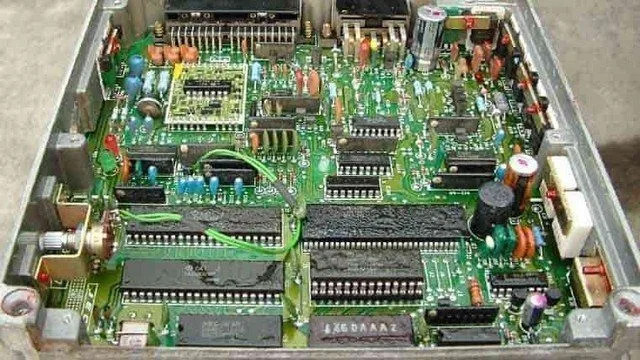
Whenever the ignition is turned on and the PCM is powered, several controller self-tests are performed. In addition to running internal controller self-tests, the Controller Area Network (CAN) is used to compare signals from each individual module to ensure that the various controllers interface correctly.
If a problem is detected in the monitoring of the generator lamp control circuit, a P0623 code will be stored and a Malfunction Indicator Lamp (MIL) may illuminate. Depending on the perceived severity of the malfunction, several failure cycles may be required for the MIL to illuminate.
Internal control module codes should always be taken seriously. A stored P0623 code could lead to various driving issues, including a no-start condition and/or a dead battery.
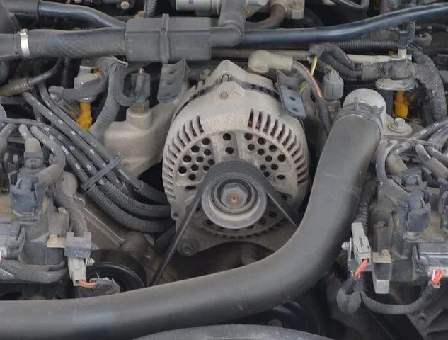
A typical alternator:
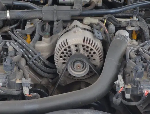
P0623 Alternator
What are some of the symptoms of the code?
Symptoms of a P0623 trouble code may include:
Engine driving problems
Engine idling roughly
Engine stalling inadvertently
Delayed engine starting
Other stored codes
What are some common causes of the code?
Causes
of this code may include:
Faulty PCM
PCM programming error
Open or shorted generator lamp control circuit
Excessive resistance in individual cells
Faulty alternator/generator
Faulty generator lamp bulb
What are the troubleshooting steps for P0623?
A diagnostic scanner, a battery/alternator tester, a digital volt/ohmmeter (DVOM), and a reliable source of vehicle information will be needed to diagnose a P0623 code.
Consult your vehicle’s information source for Technical Service Bulletins (TSBs) that match the stored code, the vehicle (year, make, model, and engine), and the symptoms presented. If you find the appropriate TSB, it may provide useful diagnostic information.
Start by connecting the scanner to the vehicle’s diagnostic port and retrieving all stored codes and freeze frame data. You’ll want to note this information, just in case the code proves to be intermittent. After recording all relevant information, clear the codes and test-drive the vehicle until the code resets or the PCM enters readiness mode. If the PCM enters readiness mode, the code is intermittent and will be more difficult to diagnose. The condition that caused the P0623 to be stored may even need to worsen before a diagnosis can be made. If the code resets, continue with your diagnosis.
Use the battery/alternator tester to test the battery and ensure it is sufficiently charged. If not, charge the battery as recommended and test the alternator/generator. Follow the manufacturer’s recommended specifications for minimum and maximum voltage output requirements for the battery and alternator. If the alternator/generator is not charging, proceed to the next step in your diagnosis.
Use your vehicle information source to obtain connector face views, connector pinout diagrams, component locators, wiring diagrams, and diagnostic flowcharts related to the code and the specific vehicle.
Check for battery voltage on the alternator/generator warning lamp circuit using the appropriate wiring diagram and your DVOM. If not, check the system fuses and relays and replace faulty parts as needed. If voltage is found at the generator warning lamp, suspect a faulty alternator/generator warning bulb.
If the alternator is charging, the alternator/generator warning lamp bulb is functioning correctly, and the P0623 continues to reset, use the DVOM to test the controller power fuses and relays. Replace blown fuses as needed. Fuses should be tested under load.
If all fuses and relays appear to be functioning as expected, a visual inspection of the wiring and harnesses related to the controller is necessary. You will also want to check the chassis and engine ground connections. Use your vehicle information source to obtain ground locations for the related circuits. Use the DVOM to test ground integrity.
Visually inspect the system controllers for signs of water, heat, or collision damage. Any damaged controller, especially by water, should be considered faulty.
If the controller power and ground circuits are intact, suspect a faulty controller or a controller programming error. Replacing the controller will require reprogramming. In some cases, you can purchase pre-programmed controllers from aftermarket sources. Other vehicles/controllers will require on-board reprogramming that can only be performed by a dealer or other qualified source.
If the charge lamp does not illuminate during key-on engine-off (KOEO) conditions, suspect a faulty generator warning lamp bulb
Test the controller ground integrity by connecting the DVOM’s negative test lead to ground and the positive test lead to battery voltage