What does it mean?
This is a generic diagnostic trouble code (DTC) for the powertrain and generally applies to OBD-II vehicles. This may include, but is not limited to, vehicles from, etc. Although generic, the exact repair steps may vary depending on the year, make, model, and powertrain configuration.
When a P062C code is stored, it means the Powertrain Control Module (PCM) has detected an internal performance error with the Vehicle Speed Sensor (VSS) signal. Other controllers may also detect an internal PCM performance error (in the VSS signal) and cause a P062C to be stored.
The internal control module monitoring processors are responsible for various controller self-test tasks and the overall responsibility of the internal control module. The input and output signals of the VSS signal are self-tested and are continuously monitored by the PCM and other associated controllers. The Transmission Control Module (TCM), Traction Control System Module (TCSM), and other controllers are subject to interaction with the VSS signal.
The VSS is typically an electromagnetic sensor that interacts with a type of ring, wheel, or toothed reluctor gear that is mechanically attached to an axle, transmission/transfer case output shaft, or driveshaft. When the axle rotates, it spins the reluctor ring. As the reluctor passes near (very close to) the sensor, the notches on the reluctor ring create interruptions in the electromagnetic sensor’s circuit. These interruptions are received by the PCM (and other controllers) as waveform patterns. The faster the waveform patterns are entered into the controller, the higher the estimated vehicle speed. As the waveform input slows, the estimated vehicle speed (as perceived by the controller) decreases. These input signals are compared (between modules) via the Controller Area Network (CAN).
Whenever the ignition is turned on and the PCM is powered up, self-tests of the VSS signal are initiated. In addition to running internal controller self-tests, the Controller Area Network (CAN) also compares the signals from each individual module to ensure each controller is functioning correctly. These tests are performed simultaneously.
If the PCM detects discrepancies in the VSS inputs/outputs, a P062C code will be stored and a Malfunction Indicator Lamp (MIL) may be illuminated. Additionally, if the PCM detects a discrepancy between any of the onboard controllers, which would indicate an internal VSS error, a P062C code will be stored and a Malfunction Indicator Lamp (MIL) may be illuminated. Multiple failure cycles may be required for MIL illumination, depending on the perceived severity of the malfunction.
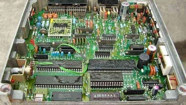
Photo of a PCM with the cover removed:

Powertrain Control Module PCM
How severe is this DTC?
Internal Control Module Processor codes should be classified as severe. A stored P062C code could result in erratic automatic transmission shift patterns and erratic operation of the speedometer/odometer.
What are some of the symptoms of the code?
Symptoms of a P062C fault code may include:
Erratic speedometer/odometer operation
Erratic transmission shifting patterns
Illumination of the service engine soon light, traction control light, or anti-lock brake light
Unexpected activation of the traction control system anti-lock braking system (if applicable)
Traction control and/or ABS codes may be stored
The ABS system may be rendered inoperative in some cases
What are some of the common causes of the code?
Causes
of this P062C DTC code may include:
Faulty controller or controller programming error
Excessive metal debris buildup on VSS
Damaged or worn teeth on the reluctor ring
A faulty VSS
A faulty controller power relay or blown fuse
Open or shorted circuit or connectors in the CAN harness
Insufficient control module ground
Open or shorted circuits between the VSS and the PCM
What are the troubleshooting steps for P062C?
Even for the most experienced and well-equipped professional technician, diagnosing a P062C code can prove very difficult. There is also the issue of reprogramming. Without the necessary reprogramming equipment, it will be impossible to replace a faulty controller and perform a successful repair.
If any ECM/PCM power codes are present, they will obviously need to be corrected before attempting to diagnose a P062C. Additionally, if there are any VSS codes, these should be diagnosed and repaired first.
Several preliminary tests can be performed before declaring an individual controller faulty. A diagnostic scanner, a digital volt/ohmmeter (DVOM), and a reliable vehicle information source will be needed. An oscilloscope will also prove useful when testing VSS and VSS circuits.
Connect the scanner to the vehicle’s diagnostic port and retrieve all stored codes and freeze frame data. You will want to note this information, just in case the code proves to be intermittent. After recording all relevant information, clear the codes and test drive the vehicle until the code resets or the PCM enters readiness mode. If the PCM enters readiness mode, the code is intermittent and will be more difficult to diagnose. The condition which caused the P062C to be stored may even need to worsen before a diagnosis can be made. If the code resets, continue with this short list of preliminary tests.
When trying to diagnose a P062C, information can be your best tool. Search your vehicle information source for Technical Service Bulletins (TSBs) that parallel the stored code, the vehicle (year, make, model, and engine), and the symptoms presented. If you find the right TSB, it may provide diagnostic information that will assist you significantly.
Use your vehicle information source to obtain connector face views, connector pinout diagrams, component locators, wiring schematics, and diagnostic flowcharts related to the code and the specific vehicle.
You can use the scanner (data stream) or the oscilloscope to test the VSS output, with the transmission engaged. If using the scanner, narrowing the data stream (to display only relevant fields) will increase the accuracy at which the desired data is displayed. Watch for inconsistent or erratic VSS readings.
The oscilloscope provides a more precise data sample. Use the positive test lead to test the VSS signal circuit (negative test lead grounded to the battery). Watch for faults or voltage spikes in the VSS signal circuit waveform pattern.
The DVOM can be used to perform a resistance test on the VSS sensor (and VSS circuits) if necessary. Replace sensors that do not meet manufacturer specifications.
Use the DVOM to test controller power fuses and relays. Test and replace blown fuses as needed. Fuses should be tested with the circuit loaded.
If all fuses and relays appear to be functioning as expected, a visual inspection of the wiring and harnesses related to the controller is warranted. You will also want to check chassis and engine ground junctions. Use your vehicle information source for ground locations for related circuits. Use the DVOM to test ground integrity.
Visually inspect system controllers for signs of water, heat, or collision damage. Any damaged controller, especially by water, should be considered faulty.
If the controller power and ground circuits are intact, suspect a faulty controller or a controller programming error. Replacing the controller will require reprogramming. In some cases, you can purchase pre-programmed controllers through aftermarket sources. Other vehicles/controllers will require onboard reprogramming that can only be performed by a dealer or other qualified source.
Unlike most other codes, P062C is likely caused by a faulty controller or a controller programming error
Test system ground integrity by connecting the DVOM negative test lead to ground and the positive test lead to battery voltage