What does it mean?
This generic powertrain diagnostic trouble code (DTC) generally applies to many OBD-II vehicles. This may include, but is not limited to, vehicles from Chevrolet, Ford, VW, Buick, Cadillac, etc.
A stored P050F code means that the Powertrain Control Module (PCM) has received an input signal from the Vacuum Brake Sensor (VBS) indicating a condition of insufficient vacuum at the brake booster servo.
Although there are several different types (including hydraulic and electronic) of brake assist systems, this code applies only to those that use engine vacuum and a vacuum brake booster.
The vacuum brake booster is located between the brake pedal and the master cylinder. It is bolted to the cabin firewall (usually in front of the driver’s seat). It is accessible with the hood open. One end of the booster actuator rod protrudes through the firewall and attaches to the brake pedal arm. The other end of the actuator rod pushes the master cylinder piston, which forces brake fluid through the brake lines and triggers braking at each wheel.
The brake booster consists of a metal housing with a pair of large vacuum diaphragms inside. This type of brake booster is called a dual-diaphragm vacuum brake booster. There are vehicles that use a single-diaphragm booster, but this is rare. With the engine running, a constant vacuum is supplied to the diaphragm, which slightly pulls on the brake pedal arm. A one-way check valve (in the vacuum supply hose) prevents vacuum loss when the engine is under load.
While most diesel vehicle applications use a hydra-boost system, others use a vacuum brake booster. Since diesel engines do not produce vacuum, a belt-driven pump is used as the vacuum source. The rest of the booster system works the same way as in a gasoline engine system.
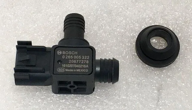
The typical VBS configuration involves a pressure-sensitive resistor inside a small vacuum diaphragm, enclosed in an airtight plastic housing. Vacuum pressure (air density) is measured in kilopascals (kPa) or inches of mercury (Hg). The VBS is inserted through a thick rubber grommet and into the vacuum brake booster housing. When vacuum pressure increases, the VBS resistance decreases. This results in an increase in the VBS circuit voltage. When vacuum pressure decreases, a reverse action occurs. The PCM receives these voltage variations as changes in the vacuum brake booster pressure and reacts accordingly.
If the PCM detects a vacuum level at the brake booster that is not within a defined parameter, a P050F code will be stored and a Malfunction Indicator Lamp (MIL) may be illuminated.
Photo of a brake booster pressure (vacuum) / VBS sensor:

How severe is this DTC?
Low vacuum pressure at the brake booster can lead to increased effort required to activate braking. This could result in a collision with another vehicle. A P050F should be addressed urgently.
What are some of the symptoms of the code?
Symptoms of a P050F engine code may include:
Audible hissing when pressing the brake pedal
Increased effort required to push the brake pedal
Other codes might be stored, including Manifold Absolute Pressure (MAP) codes
Engine drivability issues created by a vacuum leak
What are some of the common causes of the code?
Causes
of this code may include:
Internal leak in the vacuum brake booster
Faulty vacuum brake sensor
Cracked or disconnected vacuum hose
Faulty one-way check valve in the vacuum supply hose
Insufficient engine vacuum
What are the troubleshooting steps for P050F?
First, if there is a hissing sound when you press the brake pedal and the pedal pressure requires increased effort, the brake booster is faulty and will need to be replaced. A loaded booster (sold with the master cylinder included) is recommended because master cylinder leakage is the main contributing factor to booster failure.
You will need a diagnostic scanner, a manual vacuum gauge, a digital volt/ohmmeter, and a reliable source of vehicle information to diagnose a P050F code.
Diagnosing a P050F code would start (for me) with a visual inspection of the booster’s vacuum supply hose. If the hose is connected and in good working order, start the engine (KOER) and secure the vehicle in park or neutral. Carefully remove the one-way check valve (at the end of the vacuum supply hose) from the booster and ensure there is sufficient vacuum reaching the booster. You can use the manual vacuum gauge to test for sufficient vacuum if in doubt.
Engine vacuum requirements can be found in the vehicle information source. If the engine is not producing sufficient vacuum, it will need to be repaired before continuing your diagnosis.
If there is sufficient vacuum at the booster and it appears to be in working order, consult your vehicle information source for component testing procedures and specifications. You should also find wiring diagrams, connector face views, and connector pinout charts. These resources will be necessary for proper diagnosis.
Step 1
With the key on and engine off (KOEO), disconnect the VBS connector and use the positive test lead of the DVOM to check for reference voltage at the appropriate pin of the connector. Test for a ground using the negative test lead. If reference voltage and a ground are present, proceed to Step 2.
Step 2
Use the DVOM (on the ohms setting) to check the VBS. Follow the manufacturer’s testing procedure and specifications to test the VBS. If the sensor does not meet specifications, it is no good. If the sensor is good, proceed to Step 3.
Step 3
With KOER, use the positive probe lead of the DVOM to probe the signal voltage at the VBS connector. Ground the negative test lead to a known good battery ground. The signal voltage should reflect a degree similar to that displayed by the MAP sensor on the scanner’s data display. A chart of vacuum pressure to voltage can also be found in your vehicle information resource. Compare the voltage found at the signal circuit to the appropriate input on the chart. Suspect the VBS is faulty if it does not match the chart. If the voltage is within specifications, proceed to Step 4.
Step 4
Locate the PCM and use the DVOM to ensure that the VBS signal circuit voltage is present there. Probe the VBS signal circuit using the positive test lead of the DVOM. Connect the negative test lead to a good ground. If the VBS signal you found at the VBS connector is not present on the corresponding circuit of the PCM connector, suspect you have an open circuit between the PCM and the VBS.
If all circuits are in order and the VBS meets specifications; you may have a PCM problem or a PCM programming error.
Check Technical Service Bulletins (TSBs) for entries that have the same code and symptoms. The correct TSB can help you considerably in your diagnosis
Only condemn the PCM after all other possibilities have been exhausted