
Learn how to check an oxygen sensor
Learning how to check an oxygen (O2) sensor will help you confirm a potential problem with the sensor in your vehicle before spending time and money replacing a unit that might not even need replacement in the first place. Oxygen sensors detect the amount of oxygen in the exhaust stream and convert this information into a voltage signal that your car’s computer uses to control the fuel ratio and emissions.
However, whenever the sensor signal changes—and remains outside of—its normal operating parameters, it forces the computer to store a fault code in memory and turn on a malfunction indicator light (MIL) or Check Engine light on your dashboard to alert you to the problem.
Nevertheless, whether you suspect a bad oxygen sensor or a computer fault code points to a potential issue with the O2 sensor, the problem might lie elsewhere. The computer is only informing you where the problem was detected. For example, you might have a loose or torn intake hose, causing the sensor to read a consistently high oxygen level in the exhaust stream; or the sensor’s electrical connector might have come loose, preventing the device from operating. Instead, the computer detects abnormal sensor operation.
So, before replacing the unit, you can use the sensor’s operating characteristics to check if you actually need to replace it.
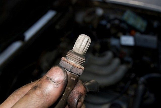
An oxygen sensor can be located near the exhaust manifold.
Connecting Your Voltmeter to the Oxygen Sensor
To perform this test, you will need a digital voltmeter with 10-megohm impedance. Most digital voltmeters come with 10-megohm protection to prevent the meter from drawing too much electrical current and damaging electrical or electronic components during a test.
Additionally, before starting your tests, locate the oxygen sensor you want to troubleshoot. On vehicle models from before 1996, you will typically find the sensor on or near the exhaust manifold. On 1996 and newer models, you will see one sensor near the exhaust manifold and another near the catalytic converter. However, some vehicle models have up to five or more sensors. Make sure you know which sensor you need to check.
When retrieving diagnostic trouble codes (DTCs) from your car’s computer, you may also get information about the specific sensor involved, depending on your scan tool’s capabilities. For example, you might get a Bank I, Sensor 1 failure, which points to the O2 sensor on or near the exhaust manifold on the cylinder head that contains cylinder number 1. A Bank I, Sensor 2, points to the sensor on the same side but further down the exhaust system, likely just before or after the catalyst. The same applies to the other cylinder head—on V-type engines—which is considered Bank II.
To locate Banks I and II, consult your vehicle’s repair manual if necessary.
- Next, if the sensor you are testing has more than one wire (heated sensor), locate the signal wire by consulting your vehicle’s repair manual if necessary.
- A single-wire sensor uses this wire as the signal wire.
- Two-wire sensors use one wire for the sensor signal and the other to power the heater.
- Three-wire models use one wire for the signal and the other two wires to power and ground the heater.
- Four-wire sensors, however, use one of the wires to ground the sensor itself.
To identify the wires, refer to the wiring diagram in your vehicle’s repair manual. If you don’t have the manual, purchase an inexpensive aftermarket manual for your specific vehicle make and model at your local auto parts store or online.
- Once you have the appropriate voltmeter on hand and have located the sensor, warm up your car’s engine to operating temperature. You can do this by taking your car for a 20-minute drive on the highway or by idling the engine for about 15 to 20 minutes at a fast idle speed.
- Turn off the engine and set your voltmeter to the DC mV (millivolt) scale.
- If you are testing an O2 sensor near the catalytic converter, lift your vehicle using a floor jack and safely support the vehicle on a couple of jack stands and block the rear wheels.
- Be careful when connecting your meter. When the engine is at operating temperature, the exhaust manifold and pipes are extremely hot. Do not burn yourself and keep your meter and probes away from hot surfaces.
On sensors with one to three wires, connect the meter’s red probe to the sensor’s signal wire and the meter’s black probe to a good ground on your engine. On four-wire sensors, connect the meter’s black probe to the sensor’s ground wire. If necessary, consult the wiring diagram in your vehicle’s repair manual.
To connect your meter’s probe to the wire, use a wire piercing probe or probe the sensor through the connector. With some sensors, however, it is difficult to probe the signal wire through the connector. To overcome this limitation, you can unplug the sensor and connect a strand of copper wire to the connector pin for the signal wire, then plug the electrical connector back in, leaving the strand of wire sticking out from the connector. This will give you a bare wire that you can connect to your meter’s probe for testing. Just make sure the bare wire does not touch ground.
Another option is to pierce the sensor’s signal wire through the insulation with a pin and connect the meter’s probe to the pin. But keep the pin from touching ground.
If you decide to use this latter method, after finishing your tests, remove the pin and cover the pierced wire section with electrical tape to prevent moisture and corrosion from seeping into the wire.
Reading Oxygen Sensor Signals
Start the engine and check the sensor’s voltage signals on your voltmeter. The sensor voltage should cycle or fluctuate within the range of about 100 mV-900 mV (0.10 to 0.90 V). This means the sensor is working properly.
If the O2 sensor only produces a low or high voltage signal, either you have an engine performance issue or the oxygen sensor has stopped working. To check the sensor’s operation, perform the following two tests.
Test the Oxygen Sensor’s Response to a Lean Fuel Condition
- First, disconnect the hose from the positive crankcase ventilation (PCV) valve leading to the intake manifold. This will allow more air to enter the engine. If you need to locate the PCV valve, consult your vehicle’s repair manual.
- Check the voltmeter reading of the sensor signal. An oxygen sensor interprets an increase in oxygen as a lean fuel condition and outputs a signal close to 200 mV (0.20 V). If the sensor does not respond accordingly or takes time to respond, the sensor is not functioning properly.
- Reconnect the hose to the PCV valve.
Test the Oxygen Sensor’s Response to a Rich Fuel Condition
- Disconnect the plastic air intake duct from your vehicle’s air filter.
- Block the opening of the duct leading to the engine with a clean cloth. This will reduce the amount of air entering the engine.
- Check the voltmeter reading of the sensor signal. An oxygen sensor interprets a decrease in oxygen as a rich fuel condition and outputs a signal close to 800 mV (0.80 V). If the sensor does not respond accordingly or takes time to respond, the sensor is not functioning properly.
- Reconnect the air duct to the air filter and turn off the engine.
If your vehicle’s oxygen sensor responded correctly to your tests, you might have an issue with another component affecting fuel efficiency. The engine might have a vacuum leak, a problem in the ignition system, or something similar. If your sensor did not respond correctly to your tests, it has stopped working and you need to replace it.