How to Check and Change Transmission Fluid

Transmission fluid performs very important functions. It lubricates the contacting elements of the transmission, removes dirt and wear products, and facilitates cooling. In automatic transmissions, this working fluid also transfers torque between the components of a torque converter. Therefore, most car manufacturers recommend monitoring the level and condition of the transmission fluid in the gearbox. We will explain how to check its level in different vehicles and also discuss situations where it might need changing.

WHAT ARE THE SYMPTOMS OF BAD TRANSMISSION FLUID?

The following signs indicate that there is not enough oil in the gearbox or that it is time to replace it:

  • unwanted noises and vibrations during gear shifting;
  • in winter, you might encounter problems with shifting when the assembly has not yet warmed up;
  • dynamics could worsen in vehicles with automatic transmission;
  • jerky gear shifting;
  • delayed gear shifting;
  • automatic transmission upshifts or downshifts when it shouldn’t.

HOW TO CHECK THE TRANSMISSION FLUID LEVEL?

To check the oil level in a manual transmission, proceed as follows:

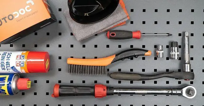
  1. Prepare all necessary tools and chemicals: a wrench, WD-40, a wire brush, clean rags or paper towels. You might also need oil – you must use the same type as what is in the gearbox now. Information about the fluid used in your car model should be specified in the vehicle manual. If not, seek professional assistance.
Prepare all necessary tools and chemicals
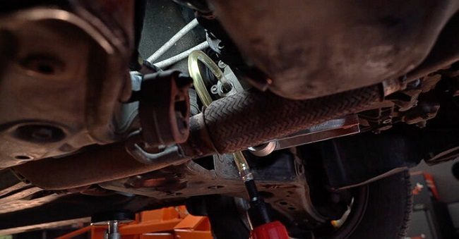
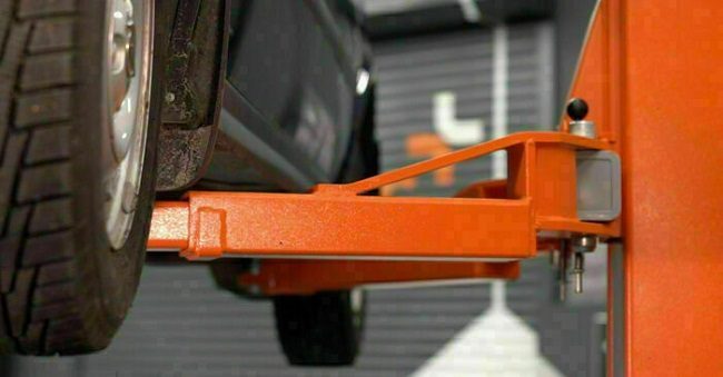
  1. Lift your car on a lift or over an inspection pit. If you don’t have such equipment and your car is front-wheel drive, remove the left front wheel to access the inspection window located on the transmission housing.
  2. Engage the parking brake.
  3. If you have just turned off the engine, wait a few minutes until the oil drains into the housing.
  4. Clean the filler plug and the surrounding area with a wire brush. Wipe with a clean cloth and solvent. This will help prevent dirt from entering the device.
Clean the filler plug and the surrounding area with a wire brush
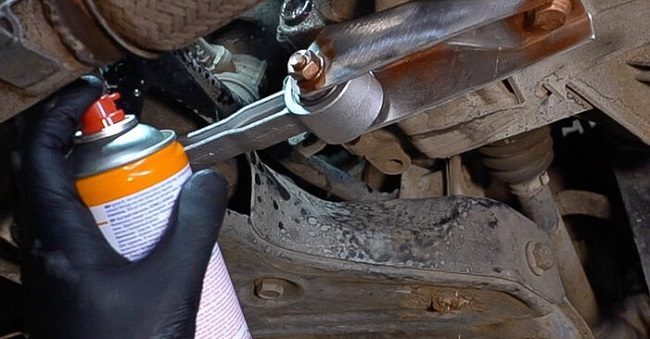
  1. Unscrew the cap that closes the opening. If it is stuck, use WD-40 to loosen it.
Unscrew the cap that closes the opening
  1. Check the amount of oil in the gearbox. Its level should reach the lower edge of the hole.
  2. If necessary, add fluid using a syringe.
If necessary, add fluid using a syringe
  1. Wipe oil traces from the transmission housing with a cloth or paper towel.
  2. Screw the plug back in.
  3. Reinstall all units to their place in reverse order.
Automatic transmissions usually have a dipstick to check the automatic transmission fluid (ATF) level.

The checking procedure is as follows:

  1. Park your vehicle on a level surface.
  2. Open the hood.
  3. Find the transmission dipstick. Usually, its handle is brightly colored, often orange. If necessary, consult the vehicle manual for the dipstick location.
  4. Start the engine. Let it run for a while to warm up.
  5. If you are not performing the test right after driving, cycle through all modes by holding the lever in each position for about three seconds. This will help distribute the transmission fluid through the channels.
  6. Place the lever in “Park” or “Neutral” position depending on the vehicle model. The exact selector position is often indicated on the dipstick.
  7. Engage the parking brake.
  8. Consult the vehicle manual to see if the engine should be running or turned off for the check. Specifically, in some Acura and Honda models, the powertrain must be shut off after warming up.
  9. Remove the dipstick from the transmission and wipe it with a clean, lint-free cloth.
  10. Insert the dipstick all the way down, then remove it again.
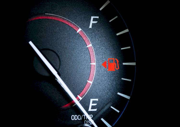
  11. Look at the dipstick. You will see two marks on it. One indicates the transmission fluid level on a cold engine and the second – on a hot engine. Usually, they have corresponding markings: either “Cold” and “Hot”, or numbers indicating the temperature. Since your engine is now hot, the oil trace on the dipstick should be at the “Hot” mark, or at a higher temperature, but not above. It is not recommended to measure the transmission fluid level on a cold engine as the results will be inaccurate.
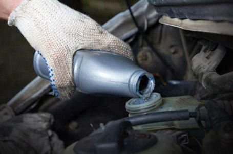
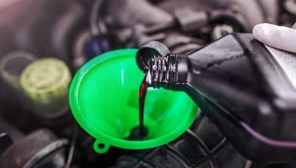
  12. If necessary, top up the ATF in the transmission. To do this, stop the engine and use a funnel.
  13. Wait for the oil to drain into the oil pan.
  14. Start the engine and check the transmission fluid level again.
Some models, like the BMW E46, BMW E39, Audi A4, Audi A6, Volkswagen Passat, for example, are equipped with transmissions without a dipstick.

To check if they are full enough or not, proceed as follows:

  1. Warm up the transmission to operating temperatures by driving a distance of about 15 kilometers.
  2. Place the vehicle on a lift, inspection pit, or car ramp so you can reach the underbody.
  3. Start the engine.
  4. Place the gear selector in the corresponding mode – “Park” or “Neutral”.
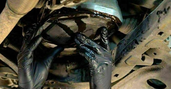
  5. Unscrew the inspection plug at the bottom of the transmission. If fluid leaks from the hole, there is no need to fill it. Screw the plug back in.
  6. If nothing leaks out, it means there is not enough oil.
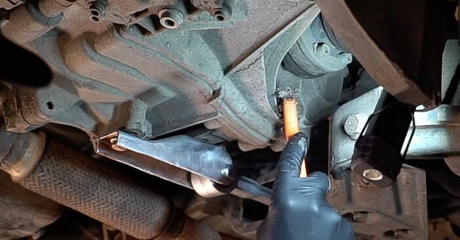
  7. Pour some ATF through the filler opening using a pump or a special hose and funnel, until it starts leaking from the inspection hole.
  8. Close the hole with the cap.
  9. Start the engine.
  10. Unscrew the plug again and repeat the filling procedure.
  11. As soon as the ATF starts leaking again, close the hole.
  12. Cycle the gear selector through all modes.
  13. Open the inspection hole and fill the fluid for the last time.
  14. Screw in the inspection and filler plugs.
  15. Wipe streaks from the transmission.

WHEN SHOULD YOU CHANGE THE TRANSMISSION FLUID?

It is recommended to replace the manual transmission oil every 80,000 – 100,000 km or after 5 years of operation, whichever comes first. In semi-automatic transmissions, the fluid is replaced every 60,000 km. Oil change intervals for automatic transmissions of different designs vary even more – from thirty to several hundred thousand kilometers. The exact replacement intervals for your vehicle model are specified in the owner’s manual.

Sometimes the transmission fluid loses its properties before its due date. This is caused by:

  • Aggressive driving behavior.
  • Towing a heavy trailer.
  • Spinning the wheels on slippery surfaces for too long.
  • Inappropriate ATF.
  • Driving in traffic jams in hot weather for too long.
  • Incorrect gear shifting.
Therefore, whenever you check the oil level, put a drop of transmission fluid on a paper towel and examine the stain. It must not contain any foreign bodies. Black residue on the dipstick, a strong burnt smell, cloudiness, or a significant color change, for example, if the oil that was red or yellow has turned dark brown or black, are other indications that the fluid is worn out.

HOW TO CHANGE GEARBOX OIL ON YOUR OWN?

To change the gear oil in a manual transmission, proceed as follows:

  1. Find out how much gear oil your transmission can hold. This information is in the vehicle manual. In addition to the required amount of fluid, depending on the vehicle design, you will need a transmission housing gasket or an O-ring for the drain plug, sealant, a container to collect the used oil, a funnel and a hose or a syringe, a cloth, and wrenches to undo the fasteners.
  2. Before starting, drive 5 to 10 km to let the oil warm up and make it less viscous: it will be easier to drain.
  3. Place your car on a lift, inspection pit, or car ramp. If necessary, secure the wheels with wheel chocks.
Place your car on a lift, inspection pit, or car ramp
  1. Remove the protective plate.
  2. Place a container under the oil pan.
Place a container under the oil pan
  1. Remove the drain plug (for example, on Renault Mégane, Audi 100, and Audi A6) and let the transmission fluid drain out. If there is no drain plug (as in Opel Astra or Chevrolet Lacetti, for example), loosen the oil pan fasteners, wait for the oil to leak out, then remove the component by tilting it very carefully to one side.
loosen the oil pan fasteners
  1. Using brake cleaner, remove dirt from the mounting seat of the pan or the plug threads.
Using brake cleaner, remove dirt from the mounting seat of the pan or the plug threads
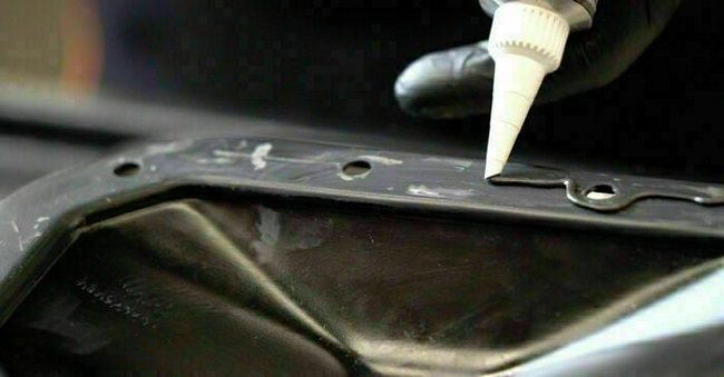
  1. If you removed the oil pan during the work, clean the contact surfaces of the old gasket residue, wipe them with solvent, install a new gasket using sealant. Put the oil pan back in place.
Install a new gasket using sealant
  1. If you removed the plug, replace its O-ring and close the drain hole with it.
  2. Use a hose and funnel to pour the required amount of fluid into the transmission through the bleeder. You can also pour it with a syringe through the inspection hole.
  3. Reassemble everything in reverse order.
The ATF in an automatic transmission should be changed in a garage. You will not be able to remove all the oil yourself. To pump it out, special equipment is used, which can be found in an auto repair shop.

Conclusion

Changing the transmission fluid and topping it up on time will help significantly extend the lifespan of both manual and automatic transmissions and ensure their long and stable operation. Follow our advice and you can check the oil level and quality yourself to decide on the next steps.

Spongy Brake Problem: Causes and Solutions

In reality, a functioning brake pedal will be firm under your foot when you press it. The term spongy brakes indicates the condition where the brake pedal loses this firmness and the brakes do not feel stable.

Such a problem of a soft brake pedal can occur for various reasons such as air in the line, holes in the brake lines, or worn calipers. If the brakes are spongy, you should immediately have the car’s braking system diagnosed and take the necessary measures, as this creates a potentially dangerous condition when driving.

What Causes Spongy Brakes?

Spongy brakes can have many reasons. Discover the causes of spongy brakes and how we can help you fix them.

1. Leak in the Brake Lines

Rust from road salt and moisture can corrode a brake and create holes causing the internal fluid to leak out of the line. If this happens, the fluid level will drop, leading to a loss of hydraulic pressure. If your brakes are soft, check the lines and replace them as soon as possible if you find a leak, which usually leads to spongy brakes. If you find a leak, you must replace the brake line as soon as possible.

What Causes Spongy Brakes

2. Brake Fluid Level

If the brake fluid level is low or depleted, it can make the brakes spongy. Open your car’s hood and remove the cap from the brake master cylinder. Now, check the fluid level. If the level is low, fill it and recheck the brakes.

3. Air in the Brake Line

This is the most common cause of spongy brakes. To stop vehicles, braking systems rely on evenly distributed hydraulic pressure. The car’s brake lines should only contain brake fluid. However, as air enters the lines, it interferes with the fluid flow, which can cause soft brakes. Bleeding the brakes is the only solution to get rid of this air.

4. Corroded Disc Brake Calipers

Just like brake lines, disc brake calipers can also accumulate rust and corrode. Brake fluid can leak through damaged areas, causing a loss of hydraulic pressure. If your brakes have felt soft lately, you should check the calipers.

5. Faulty Wheel Cylinder

Any problem with the wheel cylinder should be given the highest importance as it may require changing some brake components. A faulty wheel cylinder is another cause of a soft brake pedal. Rust can corrode it and create holes for brake fluid to escape. As you already know, loss of brake fluid leads to a loss of hydraulic pressure, which in turn causes a spongy brake problem.

6. Adjusting Rear Brake Shoes

The rear shoes are not adjusted as they wear if pumping your vehicle’s brake pedal improves the brake pedal. Shoe wear should be checked and adjusted if necessary. You should use the parking brake from time to time. Engaging the parking brake causes automatic adjustment of the brake shoes.

7. Worn Brake Pads

Remove the front and rear wheels to check for excessive wear on the brake pads. The sad news is that brake pads are the automotive parts responsible for the entire braking system. They help the car stop instantly when you press the brakes. For this reason, it is necessary to replace them if they appear extremely worn for your safety.

How to Fix Spongy Brakes

3 Symptoms of Spongy Brakes

Brake Warning Light is On

When the brake warning light illuminates on your vehicle’s dashboard, it is a sign telling you that there is a problem with the braking system and you need to act quickly. Although spongy brakes can be a potential problem with the braking system, the brake warning light is a general indicator that something is wrong and requires special attention.

Poor Braking Performance

We believe this is the most obvious symptom when your car’s brakes are spongy. The vehicle takes longer to stop or requires more distance to come to a complete stop. You may also notice a decrease in overall braking power.

Brake Fade

This sign seems strange but it is also one of the most common symptoms of spongy brakes. If the brake pedal becomes spongy after repeated or prolonged braking, it could indicate brake fade. Brake fade occurs when the braking system overheats, leading to reduced braking efficiency.

How to Fix Spongy Brakes

If you experience spongy brakes, it is recommended to have your car inspected by a mechanic as soon as possible. Alternatively, you can apply these tips to remedy spongy brakes in the safest way possible.

1. Pump the Pedal

Since a loss of brake pressure or other causes make the brake spongy, your first reaction should be to quickly and consistently pump the brake pedal with your foot. Even if there is a fault in your braking system, this can usually generate enough pressure to stop you safely by the roadside. Additionally, check out all our experts’ maintenance tips for more information on handling soft brakes as well as routine maintenance and repairs.

2. Look for a Leak and Then Repair It

Check for signs of fluid leakage in the area behind each of your car’s wheels. Furthermore, you should look under your hood to see if your master cylinder is leaking or is damp. Then, check the master cylinder to see if it is filled up to the indicator line on the side of the reservoir. If the fluid level is low, try adding some and pumping the pedal to restore pressure in the system. Any brake fluid leak is a problem for which you should send your vehicle for repair.

3. Bleed Your Brakes

Another method is to bleed your brakes to remove excess air that may have entered the system. If you have overheated your brakes during spirited driving or towing, the fluid can boil and create gas which will make your pedal spongy, because gas is compressible, unlike liquid. Each of your brake calipers or drum brake wheel cylinders will have a bleeder screw that allows you to purge air from the lines using the brake pedal and the appropriate bleeding procedure for your vehicle. You can watch this video to learn more about how to fix a soft brake pedal with a bleeding system.

https://youtube.com/watch?v=tW1W12O9K4c%3Ffeature%3Doembed

Conclusion

Any problem with the brakes can cause minor to major accidents on the road. So, if you feel that your brakes are not as firm as they should be, immediately check the braking system to find the source of the problem.

Incorrect fuel gauge reading: what’s wrong

An incorrect fuel gauge reading does not affect engine functions and does not create any major problems.

You can drive perfectly well without damaging any major components. However, not being able to read the correct fuel level will result in running out of gas without warning.

The functions of a fuel gauge are to indicate the amount of fuel in the gas tank and to give a warning when it is time to refuel.

Driving with a low fuel level leads to many long-term consequences such as fuel pump clogging, engine overheating, and premature wear of several engine parts.

Incorrect Fuel Gauge Reading: What’s Wrong?

A vehicle’s gauge system consists of three basic parts: the gauge, the circuit, and the sender. A fault in these parts will cause the gauge to fail or give incorrect readings. The four causes of fuel gauge failure are as follows:

1. Sending Unit Failure

The most common reason a fuel gauge doesn’t work. The gauge may read the voltage return from a dead sender as “Full” or “Empty.”

incorrect fuel gauge reading
The fuel gauge will not display the correct reading. (Photo: ttnews)

The sending unit moves and continuously rubs against the variable resistor when you drive the car. The constant friction wears out the contacts, leading to their failure.

2. Circuit Problems

Depending on the source of the problem, there may be a voltage issue in the fuel sender, causing the gauge to receive no voltage response.

An interruption in the ground of the gauge or the fuel sender can also be the cause of the problem. Other reasons could be corrosion or loose connections at the fuel pump module.

3. Gas Gauge Failure

A less common reason but not entirely impossible. This can occur when the internal circuit is faulty, short-circuited, or open.

There are 3 common problems with the gas gauge that you should look into more closely.

Problem #1: The gauge stays on full even though you filled up a week ago and have been driving regularly. This is not a sudden increase in fuel efficiency; it is more likely a problem with the variable resistor.

This problem can stem from faulty wiring, an open circuit in the resistor, or, in rare cases, a faulty gauge.

Problem #2: The gauge is stuck on empty, even though you know you recently filled your tank (confirmed by your bank statement).

This problem usually comes from several causes: the float may have detached from the metal arm, making it unable to provide fuel level information.

The variable resistor could be malfunctioning, or corrosion on the system wires could disrupt the transmission of information.

Problem #3: The gauge fluctuates between full and empty seemingly without any pattern. Do you feel like you’re constantly guessing your fuel level?

This problem often results from the float getting stuck in place and then resuming movement due to the car’s motion, leading to erratic readings. Alternatively, a faulty gauge itself could be the cause of this inconsistency.

4. Non-Functional Instrument Cluster

The least common cause and its repair is the most expensive. Most modern vehicles have a fully integrated circuit. So, when one part fails, the entire unit must be replaced.

How to Identify Problems with a Fuel Gauge?

For amateurs, calling a professional mechanic is the best option. But, if you have experience, it is easy to discover problems related to incorrect fuel gauge reading with these tools:

  • A digital multimeter (DMM)
  • An electrical wiring diagram (EWD)
  • Basic hand tools

Perform the following tests to identify the source of the incorrect fuel gauge reading problem.

Instrument Cluster Self-Test: The procedure involves performing a series of tasks, including turning on the headlights, pressing the trip meter button, etc.

The task sequence could be different for older vehicles. You must consult the owner’s manual for the correct command.

incorrect fuel gauge reading
Consult the owner’s manual for the correct procedure. (Photo: Philkotse)

Fuel Sender Test. Perform the test when the tank is less than half full to avoid hot oil splashes. Use the multimeter to check the voltage on the pins, and it should be 5V or 12V on one pin.

Gas Gauge Test. This inspection involves another voltage test, and the reading should be exactly the same as the fuel sender test.

FAQ

  1. Can extreme temperatures affect the accuracy of a fuel gauge?

Yes, extremely cold or hot temperatures can temporarily affect the accuracy of the fuel gauge. However, the gauge should return to normal when the temperature becomes more moderate.

  1. Is it safe to drive with a faulty fuel gauge?

It is not recommended to drive with an inaccurate fuel gauge, as you could run out of gas unexpectedly. It is safer to rely on your odometer and fill your tank based on mileage until the gauge problem is resolved.

  1. Why does my fuel gauge fluctuate while driving even when the tank is stable?

Rapid fluctuations of the fuel gauge needle while driving can be caused by a loose wire connection, a faulty gauge, or interference from other electrical components. It is important to have it checked to ensure accurate readings.

  1. How much does it cost to correct an incorrect fuel gauge reading?

The cost of repairing a fuel gauge can vary depending on the root cause of the problem. It can range from a relatively inexpensive fuse replacement to a more costly repair of a sender or instrument cluster.

  1. How often should I calibrate or check the accuracy of my fuel gauge?

You generally do not need to calibrate your fuel gauge manually. If you suspect the reading is incorrect, it is best to address the issue as soon as you notice it rather than relying on regular calibration.

  1. Can an incorrect fuel gauge reading damage my vehicle?

While an incorrect fuel gauge reading cannot damage your vehicle, it can lead to an unexpected fuel outage, which can cause inconvenience and potentially leave you stranded. It is essential to address the issue promptly.

Conclusion

If you are experiencing problems with your fuel gauge, such as an incorrect fuel gauge reading, it is essential to address them promptly to maintain the accuracy of your vehicle’s fuel level readings and ensure a safe and hassle-free driving experience.

P0674 Cylinder 4 Glow Plug Circuit

The P0674 code refers to a failure of the glow plug in cylinder number 4 in a diesel engine. Glow plugs are essential for helping to start a diesel engine when it is cold. They heat up quickly to increase the temperature in the combustion chamber, allowing the fuel to ignite by compression.


Explanation of code P0674:

When the diesel engine is cold, the compression engine generates extremely high temperatures that can be lost quickly due to the cold cylinder head. To solve this problem, diesel engines are equipped with glow plugs that heat the combustion chamber before starting.

The P0674 code indicates that the glow plug in cylinder number 4 is not working properly. This can lead to difficulties starting the engine, especially in cold weather.


Possible symptoms:

  1. Difficulty starting when cold or after a long period of non-use (especially in cold weather).

  2. Lack of power until the engine warms up.

  3. Hesitation or misfires during acceleration.

  4. The glow plug indicator light does not turn off, indicating a problem with the preheating.


Possible causes:

  • Faulty glow plug in cylinder number 4.

  • Damaged wiring or connectors in the glow plug circuit.

  • Faulty relay or control module for the glow plug.


Diagnostic and repair steps:

  1. Test the glow plug in cylinder number 4 with a digital ohmmeter:

    • Disconnect the glow plug connector.

    • Use the ohmmeter to measure the resistance between the glow plug terminal and a good ground. The resistance should be between 0.5 and 4.0 ohms (specific values may vary depending on the vehicle model).

    • If the resistance is outside this range, the glow plug must be replaced.

  2. Check the wiring and connectors:

    • Check the glow plug wires for any short circuit, disconnected wire, wear, or deterioration.

    • Also inspect the fuses and relays associated with the glow plug system.

  3. Test the glow plug relay:

    • Check the relay by ensuring it provides adequate current to the glow plugs.

  4. Clear the codes and test:

    • Use an OBD scanner to clear the code once repairs are completed and test the system to check if the problem persists.


Recommended repair:

If the glow plug in cylinder number 4 is faulty, it must be replaced. If the problem comes from the wiring or connectors, these must be repaired or replaced. In case of a problem with the relay or control module, these will also need to be replaced.

Importance of diagnosis:

A glow plug failure can make starting difficult, especially in cold weather, and affect engine performance until it is completely warmed up. It is important to resolve this issue to avoid further engine damage and ensure its proper operation.

P06AB PCM / ECM / TCM Internal Temperature Sensor Circuit B

What does it mean?

This is a generic powertrain diagnostic trouble code (DTC) that applies to many OBD-II vehicles (1996-newer). This may include, but is not limited to, vehicles from Mazda, Honda, Dodge, Ford, BMW, VW, etc. Although generic, the exact repair steps may vary depending on the year, make, model, and powertrain configuration.

OBD-II trouble codes P06AB, P06AC, P06AD, and P06AE are associated with the “B” circuit of the internal temperature sensor of various modules. This circuit includes the Powertrain Control Module (PCM), Engine Control Module (ECM), and/or Transmission Control Module (TCM). Refer to a vehicle-specific repair guide to determine which is the “B” circuit in your particular case.

The purpose of the PCM/ECM/TCM internal temperature sensor “B” circuit is to monitor the temperature of various sensors housed within the control modules. Malfunctions are identified by the control module’s self-test failure process. On some automobiles, all three modules are integrated into a consolidated unit, typically called the PCM.

When the PCM, ECM, or TCM detects incorrect signals in the internal temperature sensor “B” circuit, code P06AB will be set, and the Check Engine light or Transmission Warning light will illuminate.

An example of a Transmission Control Module TCM:

How severe is this DTC?

The severity of this code can vary greatly, from a simple Check Engine light or Transmission Warning light on a vehicle that starts and runs, to a vehicle that may stall or not start at all. The code can be serious depending on the specific nature of the problem.

What are some of the symptoms of the code?

Symptoms of a P06AB trouble code may include:

  • Engine does not start
  • Engine may stall
  • Incorrect shifting
  • Transmission Warning light illuminated
  • Check Engine light illuminated

What are some of the common causes of the code?


Causes of this P06AB code may include:

  • Corroded or damaged connector
  • Loose or faulty control module ground strap
  • Faulty or damaged wiring
  • Faulty PCM, ECM, or TCM

What are the troubleshooting steps for P06AB?

The first step in the troubleshooting process for any malfunction is to search for Technical Service Bulletins (TSBs) for the specific vehicle by year, model, and powertrain. In some circumstances, this can save a lot of time in the long run by pointing you in the right direction.

The second step is to locate all control modules within this circuit and perform a thorough visual inspection of the associated wiring, looking for obvious faults such as chafing, rubbing, bare wires, or burn marks. This process should also include ground straps and wires. Next, check the connectors for security, corrosion, and damaged pins. This process should include the PCM, ECM, and TCM depending on the specific vehicle and control module configuration. Vehicle-specific technical data will help you locate components and the control module configuration.
Advanced Steps

Advanced steps become very vehicle-specific and require appropriate advanced equipment to perform accurately. These procedures require a digital multimeter and vehicle-specific technical references. The specific technical data will include troubleshooting charts and the proper sequence to follow to help you make an accurate diagnosis.
Voltage Checks

Specific troubleshooting guidelines must be referenced to determine the required voltage ranges for the different control modules. These references will include pin numbers and voltage requirements associated with the PCM/ECM/TCM internal temperature sensor/circuit. Most, but not all, control modules require a reference voltage of around 9 volts. Voltage requirements vary depending on the specific year and model of the vehicle.

If this process identifies a missing power source or ground, continuity tests may be required to check the integrity of the wiring, connectors, and other components. Continuity tests should always be performed with the power disconnected from the circuit, and normal readings for wiring and connections should be 0 ohms of resistance. Resistance or lack of continuity is an indication of faulty wiring that is open or shorted and must be repaired or replaced. A continuity test between the different control modules and the chassis will confirm the serviceability of the ground straps and wires. The presence of resistance indicates a loose connection or possible corrosion.

What are the common repairs for this code?

  • Cleaning corrosion from connectors
  • Repairing or replacing faulty wiring
  • Repairing or replacing faulty ground straps
  • Flashing or replacing the PCM, ECM, or TCM

Misdiagnosis can lead to the PCM, ECM, or TCM being replaced, which is often done in error when faulty wiring connections are the cause of this code. Also, on vehicles equipped with two or more control modules, the wrong module may be replaced by mistake.

I hope the information in this article has helped point you in the right direction to fix the issue with your PCM/ECM/TCM internal temperature sensor/circuit fault code. This article is strictly informational, and the technical data and service bulletins specific to your vehicle should always take priority.

P0511 Idle Air Control Circuit

What does it mean?

This diagnostic trouble code (DTC) is a generic powertrain code, meaning it applies to all vehicles from 1996 onwards (Dodge, Chrysler, Hyundai, Jeep, Mazda, etc.). Although generic, specific repair steps may vary by make/model.

When your OBD-II equipped vehicle has a malfunction indicator light (MIL) and a stored P0511 code, it means the powertrain control module (PCM) has detected a problem with the idle air control (IAC) valve circuit. If there are other more specific IAC codes, these should be diagnosed and repaired first.

The IAC system centers around a linear servo motor that controls a piston regulating the amount of air allowed to bypass the throttle plate and enter the intake manifold. Controlling the amount of air bypassing the throttle plate helps manage engine idle speed. When the throttle plate is closed (at idle), very little air is allowed into the engine through the throttle body. The engine cannot maintain idle with this small amount of air and would likely stall. An auxiliary air (vacuum) source must be provided so the engine can continue idling with the throttle plate closed. Of course, the auxiliary vacuum source would harm engine performance and fuel efficiency when the throttle plate is open (during acceleration). Hence the need for a fully adjustable, PCM-controlled vacuum source.

The IAC valve piston housing is manufactured with two separate openings that allow air to pass through. The IAC valve is typically bolted to the intake manifold, on or near the throttle body. It is positioned so that when open (piston retracted from the opening), ambient air can flow through it into the manifold, and when closed (piston blocking the opening), ambient air cannot pass through.

An example of an idle air control (IAC) valve:

The IAC is rarely fully open or closed but is constantly moving, controlled by the PCM. The PCM uses input signals from oxygen sensors, throttle position sensors, and various other sensors to determine how much air should bypass the throttle plate. When the voltage and ground signals to the IAC valve are adjusted (by the PCM), the valve responds accordingly. If engine speed levels do not match the programmed desired limits, a P0511 code will be stored and an MIL may illuminate.

Related idle air control system circuit trouble codes include:

  • P0508 Idle Air Control System Circuit Low
  • P0509 Idle Air Control System Circuit High
  • P0518 Idle Air Control Circuit Intermittent
  • P0519 Idle Air Control System Performance

Severity and Symptoms

A malfunctioning idle air control system can cause the engine to stall or idle at an unexpectedly high RPM. This code should be treated as severe and addressed urgently. Symptoms of a P0511 code may include:

  • High engine RPM level
  • Engine stalling, especially at idle
  • Unusual noises from the throttle body area
  • Other IAC-related codes

Causes

Possible causes of this code include:

  • Faulty IAC motor/valve
  • Engine vacuum leak
  • Open or shorted IAC control wires or connectors
  • Carbon buildup in the throttle body or IAC valve
  • PCM programming error or faulty PCM

Diagnostic and Repair Procedures

A good starting point is always to check the technical service bulletins (TSBs) for your specific vehicle. Your issue might be a known problem with a published fix from the manufacturer, potentially saving time and money during diagnosis.

To diagnose a P0511 code, you would need a diagnostic scanner, a digital volt/ohmmeter (DVOM), and a reliable source of vehicle information (All Data DIY will suffice).

Start by inspecting all electrical wires and connectors of the IAC system and repairing any that are damaged, corroded, or burnt. Also, check the engine for any vacuum leaks that could contribute to an uncontrollable engine speed level. If you find vacuum leaks, repair them and recheck the system.

Next, connect the scanner to the vehicle’s diagnostic connector and retrieve all stored codes and freeze frame data. It’s good practice to write this down in case the code is intermittent. Now, clear the codes and test drive the vehicle to see if the code returns. If other IAC-related codes are stored, diagnose and repair them first. Also, check all technical service bulletins and safety recalls for the vehicle and the specific malfunction. After performing all repairs, drive the vehicle normally and allow the PCM to enter readiness mode before declaring the problem fixed.

As a simple method to test the IAC system, when the engine idle speed is very high, carefully unbolt (to preserve the gasket or seal) the IAC valve from the engine and use a shop rag and your fingers to control the engine idle speed. If you can control a high idle condition after removing the IAC valve, you know the IAC system is not functioning correctly. If you cannot control the idle speed, suspect a significant vacuum leak. Major engine vacuum leaks can include PCV valves/hoses, vacuum hoses, brake booster, check valve or hoses, a stuck open EGR valve, EGR gasket leak, or an intake manifold gasket leak.

Consult your vehicle information source for the recommended method of testing the IAC motor with the DVOM. Replace the IAC motor/valve if it does not meet manufacturer specifications.

Additional Diagnostic Notes:

Disconnect all associated controllers before testing circuit resistance with the DVOM

P0235 Turbocharger/Supercharger Boost Sensor A Circuit Malfunction

What does it mean?

This diagnostic code (DTC) is a generic powertrain code. It is considered generic because it applies to all makes and models of vehicles (1996 and newer), although specific repair steps may vary slightly by model (Nissan, Honda, Renault, etc.).


The P0235 code is generic in that it refers to a problem in the turbocharger/supercharger boost sensor A circuit. Although generic in nature, never assume it is identical for all vehicles.

OBD codes do not necessarily point to a specific component, but rather to an area where the technician can look for possible causes of a problem within that circuit, which could include multiple possibilities.

All vehicles with the P0235 code have one singular point in common. It refers to an unacceptable discrepancy between the ECM’s (Electronic Control Module) programmed percentage of turbo boost at a specific RPM and the sensor signal value. These two values must coincide within close limits.
How turbocharging (forced induction) increases performance

Turbochargers force much more air into the engine than the engine is capable of under normal aspiration conditions. The greater the volume of air forced into the cylinders, the greater the increase in fuel equates to increased power.

Typically, a turbocharger can increase power by 35 to 50% in an engine specifically designed for turbocharging. The components of a conventional engine will not withstand the stresses placed on it by forced induction.

Turbochargers offer high power gains with little or no negative effects on fuel economy. They use exhaust velocity to drive the turbocharger, so it’s essentially free power. That’s the advantage. The disadvantage is that they take a beating and tend to fail at unpredictable times for a multitude of reasons. When an indication that a problem with the turbocharger has occurred, resolve it as soon as possible. A turbocharged engine greatly exaggerates engine problems due to the mass of compressed air.

Never tighten the wastegate and do not attempt to install any modification on a stock turbocharged engine for the purpose of increasing boost pressures. The fuel and timing curve of most engines will not adapt to boost pressures higher than normal and engine damage will occur.

Note: This DTC is basically identical to P0239 which refers to turbocharger “B”.

Symptoms

Symptoms of a P0235 diagnostic code may include:

The P0235 code will be set, which simply means a problem exists somewhere in this circuit preventing proper boost control. Additional pending codes may be set regarding this malfunction, each relating to a section of the circuit.
The engine may lack acceleration.
The boost pressure gauge will indicate less than 9 psi of boost or more than 14 psi of boost. Both are out of range.
Unusual noises or rattling from the turbocharger or piping.
The engine knock sensor code may appear indicating that detonation is occurring due to high cylinder head temperatures.
The engine may exhibit a general lack of power.
Exhaust smoke.
Fouled spark plugs
Abnormally high engine temperature at cruising speeds.
Hissing noises at the wastegate

Causes

Turbos typically spin at an incredible speed of 100,000 to 150,000 RPM. They are not the most tolerant of imbalance conditions or lack of clean oil to the bearing.

Potential causes of this DTC include:

  • Vacuum leak at the intake manifold
  • Dirty air filter
  • Faulty wastegate – stuck open, closed, or leaking
  • Insufficient oil supply to the main shaft bearing – blockage in the oil supply or return line.
  • Bearing failure causing slow rotation due to drag.
  • The bearing wobbles and the turbine blades hit the turbo housing.
  • Chipped, bent, or missing turbine blades, causing imbalance.
  • Oil seal leak on the compressor side of the turbo, as indicated by oil in the turbo and fouled plugs.
    Excessive axial play in the turbo
  • Faulty intercooler
  • Loose connections between the intake pipe and the throttle body
  • Cracks in the turbo housing
  • Loose exhaust manifold to turbo bolts.
  • Poor electrical connection to the Turbo boost sensor.
  • Short or open in the sensor harness between the sensor and the ECM.
  • Faulty sensor or ECM 5-volt reference driver.

Diagnostic Steps

and possible solutions

In my experience, the diagnostic flow starts with the most common turbo problems and works systematically down to the least likely. Simple tools are needed, such as a vacuum gauge and a dial indicator.

Confirm that the engine is running correctly, with no faulty plugs and no codes related to a faulty knock sensor.
On a cold engine, inspect the hose clamps at the turbo outlet, the intercooler, and the throttle body for tightness.
Try to wiggle the turbo on the exhaust flange to see if it is tight.
Inspect the intake manifold for leaks of any kind, including intake hoses.
Remove the wastegate actuator rod. Operate the wastegate manually while checking for a sticking valve causing low boost.
Locate an unused vacuum port on the intake manifold and install a vacuum gauge. Start the engine. At idle, the engine should have between 16 and 22 inches of vacuum. If it has less than 16, the catalytic converter is bad and will not allow boost to build.
Quickly rev the engine to 5000 RPM and release the throttle while observing the vacuum gauge as it displays boost pressure. If the boost pressure exceeds 19 psi, you have a faulty wastegate. If the boost does not rise between 14 and 19 psi, a problem exists with the turbo itself.
Stop the engine and let it cool. Remove the turbo outlet pipe and look inside the turbo to see if the blades are hitting the sides of the housing. Look for bent or missing blades or oil in the turbo. Spin the blades by hand and look for grinding or resistance indicating a faulty turbo.
Inspect the oil lines from the engine block to the turbo center bearing and the return line from the bearing to the oil pan for leaks.
Install the dial indicator on the turbine output shaft nose and move the turbo shaft in and out. If there is more than 0.003 inches of axial play, the center bearing is faulty.
If the turbo passes these tests, it is good. Use the service manual to test the boost sensor and harness using a volt/ohmmeter. Locate the 5-volt reference from the ECM to the sensor and confirm the voltage. No voltage present indicates an open or short in the harness or a bad ECM.
Locate the appropriate reference signal from the boost sensor to the ECM and confirm a varying voltage as RPM increases. No voltage rise indicates a bad sensor.

Troubleshooting Alternator and Charging System Issues

Troubleshooting Alternator and Charging System Problems

Alternator and charging system problems can affect your vehicle in different ways. You might notice:

(more…)

SCR NOx Catalyst Inlet Temperature Too High

Code: P214A

Definition

SCR NOx Catalyst Inlet Temperature Too High

Description

Selective Catalytic Reduction (SCR) is a technology that uses a urea-based Diesel Exhaust Fluid (DEF) and a catalytic converter to significantly reduce nitrogen oxide (NOx) emissions. The system achieves this by injecting small amounts of Diesel Exhaust Fluid into the exhaust system upstream of the catalyst, where it vaporizes and decomposes to form ammonia and carbon dioxide. The ammonia is the desired product which, in conjunction with the SCR catalyst, converts NOx into harmless nitrogen and water. Excess fuel or oil entering the exhaust system due to a faulty engine component or fuel injector can cause a temperature increase and damage the SCR catalyst. The Diesel Exhaust Fluid Dosing Control Unit is used to control the operation and monitoring of the Diesel Exhaust Fluid system.

Cause

  • EXHAUST GAS TEMPERATURE SENSOR 1/4 FAULTY IN RANGE
  • Engine misfires
  • EXCESSIVE FUEL OR OIL INTRODUCED INTO THE EXHAUST SYSTEM
  • FAULTY DOC/DPF CATALYST

How to Interpret OBD2 Error Codes Like a Pro

OBD2 (On-Board Diagnostics) codes are an essential window into a vehicle’s health status. They allow professionals and enthusiasts to quickly diagnose problems related to the engine, exhaust, or other vehicle systems. If you want to interpret these codes like a pro, here’s everything you need to know.


1. What is an OBD2 Code?

An OBD2 code is a combination of letters and numbers issued by a vehicle’s on-board diagnostic system when it detects an anomaly. These codes help identify the source of a problem.

An example code: P0302

  • P: Denotes the system (Powertrain).
  • 03: Identifies the specific function or failure.
  • 02: Locates the problem, here cylinder number 2.

Possible first letters:

  • P: Powertrain (engine and transmission).
  • C: Chassis (brakes, steering, etc.).
  • B: Body (air conditioning, airbags, etc.).
  • U: Communication network (problems related to CAN bus).

2. Structure of an OBD2 Error Code

An OBD2 code consists of 5 characters:

  • 1st character (letter): System (P, C, B, U).
  • 2nd character (digit): Code type.
    • 0: Standard generic code (applies to all brands).
    • 1: Manufacturer-specific code.
  • 3rd character (digit): Affected subsystem.
    • 1: Fuel and air measurement.
    • 2: Injection and fuel.
    • 3: Ignition system.
    • 4: Auxiliary emission control.
    • 5: Idle system.
  • 4th and 5th characters: Precisely identify the problem.

3. Tools Needed to Read an OBD2 Code

To interpret the codes, you need an OBD2 scanner.

  • Basic readers: Display error codes without details.
  • Advanced scanners: Provide descriptions, allow clearing codes, and display real-time data.
  • Mobile applications: Connect a Bluetooth OBD2 adapter for reading via your smartphone (e.g., Torque, Car Scanner).

4. Where to Plug in the OBD2 Scanner?

The OBD2 port is generally located under the dashboard, near the steering column. Plug in the scanner and turn on the ignition (without starting the engine).


5. How to Interpret an OBD2 Code?

Let’s take an example: P0420

  • P: Engine-related problem.
  • 0: Generic code.
  • 4: Auxiliary emission control system.
  • 20: Catalyst efficiency below threshold (bank 1).

This indicates that the catalyst in bank 1 (the engine side closest) is not functioning correctly, often due to a sensor problem or clogging.


6. What to Do with an OBD2 Error Code?

  1. Identify the code: Look up the meaning of the code via a manual or online.
  2. Analyze the context: The conditions that triggered the code (temperature, speed, etc.).
  3. Check common causes:
    • Faulty sensors.
    • Damaged connectors or wiring.
    • Worn mechanical components.
  4. Repair or reset:
    • After repair, clear the code to see if it returns.

7. Most Common OBD2 Codes

  • P0300: Random misfire detected.
  • P0420: Catalyst system efficiency below threshold.
  • P0171 / P0174: System too lean.
  • P0455: Evaporative emission control system leak detected (large).
  • P0500: Vehicle speed sensor malfunction.

8. Tips for Interpreting Like a Pro

  • Use an advanced scanner: It provides detailed information about codes and displays real-time data.
  • Consult manufacturer databases: Some brand-specific codes require specialized documentation.
  • Observe symptoms: Don’t rely solely on codes, but also on the vehicle’s behavior.

Conclusion

Interpreting OBD2 codes may seem intimidating at first, but with practice and the right tools, it becomes child’s play. Mastering this skill will save you time and money while extending your vehicle’s lifespan.