mass air flow sensor and related information
Check that engine light faults related to the mass air flow sensor are becoming less common, but do occur. The tricky thing with some of these types of faults is that you can have a mass air flow sensor problem without triggering the check engine light. Before getting into diagnostics, let’s start with a brief overview of the sensor itself.
The main purpose of the mass air flow sensor (MAF) is to measure the volume and density of air entering the engine at any given time. The computer uses this information together with inputs from other sensors to calculate the correct amount of fuel to deliver to the engine. This sensor’s input is also indirectly used to help calculate the desired ignition timing and transmission operation strategies. MAF sensors are primarily designed as either a “hot wire” sensor or a “hot film” sensor. Both sensors operate similarly. Hot wire sensors pass current through a platinum wire and hot film sensors pass current through a foil grid. The current level is regulated to keep the hot wire, or film, at a predetermined temperature. This temperature is either a direct value or a value that is a set number of degrees above the ambient (outside) air temperature.
So how does this tell us how much air is entering the engine? Well, when air passes through the mass air flow sensor, it cools the hot wire, increasing the amount of current needed to keep that wire at the specified temperature. The amount of cooling of the wire is directly proportional to the temperature, density, and humidity of the air passing through the sensor and, as such, the increased current required to heat the wire allows the computer to easily calculate the volume of air entering the engine.
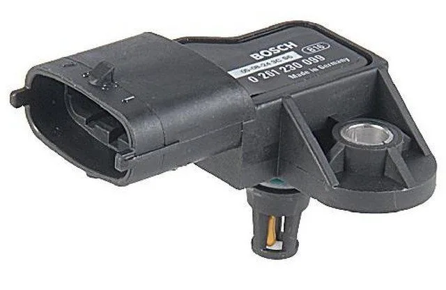
mass air flow sensor
Mass air flow sensors typically send a voltage or frequency signal to the powertrain control module (PCM). Hot wire sensors usually have an operating range of 0 to 5 volts, with idle voltage around 0.5 to 0.8 volts and full throttle application normally between 4 and 5 volts. Hot film sensors typically produce a frequency output of 30 to 50 Hz, with 30 Hz at idle and 150 Hz at full throttle. There are other subtle differences between sensors, but these do not affect the function or purpose.
So, what types of symptoms can we get from MAF sensors, and how should we test for these faults?
Well, as we mentioned earlier, MAF sensors can produce drivability symptoms without generating a check engine light code, so some specific checks are in order. To facilitate diagnosis, a scan tool should be used to monitor the sensor readings. In some cases, it is acceptable to take sensor value readings by probing the appropriate terminals on the MAF sensor again.
If specific MAF check engine codes are present, proceed with the appropriate tests. If no codes are present, or if you have lean codes that you suspect are caused by a faulty mass air flow sensor, proceed as follows. Obtain the sensor specifications from a reliable source; you can email us from the help link and we can assist you with most information. Connect a scan tool with the ability to monitor sensor valves (PIDs) and reinstall the mass air flow sensor. Record your MAF sensor reading at idle, then again at different RPM ranges. Compare the values to the specifications. Then, start at idle and increase the throttle opening while watching the MAF reading. The increase should be steadily proportional to the RPM change. Perform the same checks while lightly tapping the sensor or heating the sensor with a hairdryer. Any fluctuation or reading out of specifications indicates a mass air flow sensor or related wiring issue. Repair and retest. I would also recommend monitoring MAF values while driving the vehicle and checking the readings when the problem is present. Have an assistant drive while you check these readings. If the mass air flow reading is within specifications while a concern comes and goes, it is probably not the issue. Be sure to check all connections and air intake seals, as well as the air filter before faulting the sensor, as these types of issues can affect the readings.
On a final note; it is not always necessary to replace a mass air flow sensor whose reading is out of specifications, although most dealers will tell you otherwise! It is possible that the sensor is simply contaminated due to age or the use of oil-saturated air filters. You can try exposing the sensor’s hot wire (once the sensor is removed from the vehicle) and cleaning it with electronic parts cleaner and low-pressure air. Use appropriate precautions. Once the sensor is clean, reassemble, install, and check the operation; you may be pleasantly surprised! I hope this information has been helpful. Thank you for visiting and have a good day!