How to reset the “check engine” light?

Once you have properly diagnosed and resolved the issue that triggered the OBD fault code, you can reset or clear the engine/service engine soon light quickly using one of two methods.

Note: The code (i.e., the CEL/SES light) usually disappears after a number of driving cycles, perhaps a few days. You can choose to wait it out or follow one of these methods.

The cheap, easy, and free method

Simply disconnect your battery, turn on the headlight switch for about five to ten minutes, and reconnect the battery. It’s quite simple, but it will likely cause you to lose your radio presets and maybe other small things like that.

Using a scan tool

Most scan tools, if not all, have the ability to erase or reset codes without using tools or touching the battery. Consult your tool’s manual to learn how to do this with your specific model.

What is an OBD-II Code Reader?

Introduction

Until recently, an OBD-II code reader tool was not typically found in the DIYer’s toolbox. However, for working on vehicles from 1996 and newer, it can be very useful.

An OBD-II code reader is an electronic device that allows you to connect to your vehicle’s OBD diagnostic port and access technical information. Check other frequently asked questions for more information about OBD.

The reader enables you to view all recorded diagnostic trouble codes (DTCs), making it easier to troubleshoot issues with cars and trucks.

OBD code readers come in a variety of shapes and sizes. Some work in conjunction with a laptop and software. In these cases, you essentially get a cable and software. In other instances, the unit is portable and performs all the same functions but in a neat handheld package.

Features

The characteristics of each OBD code reader depend on the brand and model. However, it is common for most readers to have:

LCD screen display
Display diagnostic trouble codes (DTCs)
Ability to reset/clear DTC codes
Access “freeze frame” data to see what was happening when the code was triggered

High-end OBD code readers may have more advanced features such as:

Languages other than English
Code definitions directly on the unit
Display freeze frame data

Additionally, some manufacturers sell performance chips/tuners that include the OBD code reader function.
Pricing

OBD-II code readers vary in price. They range from affordable ($85) to several hundred dollars or more.

What are the OBD-II protocols?

There are five different OBD-II communication protocols:

     J1850 PWM
     J1850 VPW
     ISO9141
     ISO14230 (also known as Keyword Protocol 2000)
     CAN (ISO15765 / SAEJ2480)

What does this mean for me?

Well, generally, you’ll need to know which protocol you have when purchasing a code reader or OBD-II tool. Sometimes manufacturers label products for Ford, GM, etc., so it can be easy. However, here’s the quick way to tell what you have.

Note: At the time of writing, I don’t know if this is a 100% foolproof method to tell which protocol you have. Make sure to check with a dealership or repair manual if in doubt.

 
To find out which protocol you have, refer to the table below:
 
 
Standard Pin 2 Pin 7 Pin 10 Pin 15 Notes
PWM must have must have The connector must have pins 2, 4, 5, 10, and 16
VPW must have The connector must have pins 2, 4, 5, and 16, but not 10.
ISO must have must have The connector must have pins 4, 5, 7, and 16. Pin 15 may or may not be present.

OBD-II / Automotive Acronyms and Definitions

This is where we explain what different acronyms represent and what some other technical words mean.


From A to G

ABS – Anti-lock Braking System
A/C – Air Conditioning
AIR – Secondary Air Injection System
BARO – Barometric Pressure
CKP – Crankshaft Position Sensor
CMP – Camshaft Position Sensor
CEL – Check Engine Light – same as Malfunction Indicator Lamp (MIL) or Service Engine Soon
CO – Carbon Monoxide
CO2 – Carbon Dioxide
DEPS – Digital Engine Position Sensor
DLC – Data Link Connector
DIS – Distributorless Ignition System
DTC – Diagnostic Trouble Code
ECT – Engine Coolant Temperature
EEPROM – Electrically Erasable Programmable Read-Only Memory
EGR – EGR stands for Exhaust Gas Recirculation. It is part of the vehicle’s emissions system and is used to reduce combustion temperature and pressure to control nitrogen oxides.

The EGR system typically includes three parts: the EGR valve, an actuator solenoid, and a differential pressure sensor (DPF). These components work together to provide the correct amount of recirculation based on engine temperature, load, etc.

EVAP – Evaporative Emissions System
FTP – Federal Test Procedure

From H to M

H2O – Water
HO2S – Heated Oxygen Sensor
HC – Hydrocarbon
HVS – High Voltage Switch
IAC – Idle Air Controller
IAT – Intake Air Temperature
IC – Ignition Control
I/M – Inspection/Maintenance
KS – Knock Sensor
MAF – Mass Air Flow (Sensor)
MAP – Manifold Absolute Pressure
MIL – Malfunction Indicator Lamp – Same as Check Engine Light or Service Engine Soon
MR – Magneto-Resistive
MSC – Mass Storage Cartridge

From N to T

NOx – Nitrogen Oxides
OBD – On-Board Diagnostics
OBD-I – First Generation On-Board Diagnostics
OBD-II – Second Generation On-Board Diagnostics
OBPA – Off-Board Programming Adapter
O2S – Oxygen Sensor
OSC – Oxygen Storage Capacity
PCM – Powertrain Control Module
SES – Service Engine Soon – Same as Malfunction Indicator Lamp (MIL) or Check Engine Light (CEL)
SPS – Service Programming System
TCC – Torque Converter Clutch
TDC – Top Dead Center
TP – Throttle Position or;
TPS – Throttle Position Sensor
TWC – Three-Way Catalyst

From U to Z

UART – Universal Asynchronous Receiver and Transmitter
VCM – Vehicle Control Module
VIM – Vehicle Interface Module
VPW – Variable Pulse Width
VSS – Vehicle Speed Sensor
WOT – Wide Open Throttle


EGR: Exhaust Gas Recirculation

The EGR Valve and System – It’s Just Three Letters, but EGR Can Lead to AGGravation.

Common in automotive emission systems since the early 1970s, the EGR (Exhaust Gas Recirculation) valve controls a vehicle’s emissions of nitrous oxides or NOx. Its job is to route some exhaust gas back to the intake manifold. This lowers the combustion temperature to below 2500 degrees Fahrenheit – the temperature at which NOx gases form.


EGR flow is controlled by the engine computer, which opens or closes the valve as needed. The EGR system is, for the most part, in the “out of sight, out of mind” category and generally doesn’t require regular maintenance. But if it becomes clogged with carbon deposits, you’ll see your “check engine” light come on, and a code (perhaps P0401 or P0402 or P0403) will indicate insufficient flow. This usually results from consistently driving a vehicle on short trips that don’t allow the engine to fully warm up. Flow problems can also be caused by carbon buildup due to failing to change the oil frequently enough.

A clogged EGR valve not only leads to increased emissions, but it can also reduce fuel economy and cause rough idling, or even serious engine damage. Valves can usually be cleaned, but replacement is often recommended.

Tip?

Make sure to drive highway or freeway miles and always change the oil according to the maintenance schedule in the owner’s manual.


EBD Explained: Electronic Brakeforce Distribution

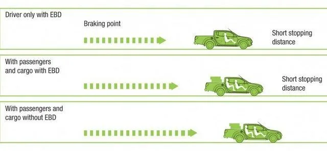
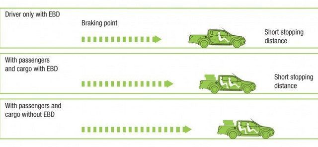
EBD (Electronic Brake Force Distribution) is a technology that allows for the automatic increase or application of a vehicle’s braking force, depending on road conditions, vehicle speed, vehicle weight, etc.


In a normal braking system, when the brake pedal is applied, brake fluid moves from the master cylinder to the brake cylinders. When the fluid enters the brake cylinder, the pressure of the applied fluid forces the two pistons to extend, which causes the brake shoes or pads to come out. This thrust or pressure is directly proportional to the thrust of the pistons, causing the shoes or pads to rub against the drum or caliper. This reaction creates friction and reduces wheel locking.

EBD electronically monitors, via sensors, road conditions, the pressure feel on the brake pedal, and the vehicle’s weight, to determine when to apply pressure to the wheel cylinders. The sensors are designed to monitor wheel movements and determine, based on weight, which wheels may need the maximum force applied, depending on the condition met. Supposedly, this aims to provide better and more precise braking under all imaginable conditions.

Since the front of a vehicle carries the most weight, the EBD system recognizes this and electronically controls the rear brakes. Thus, when the driver applies the brakes, the rear brakes do not lock up, causing a skid.

EBD is a good system for drivers because it can increase the vehicle’s ability to stop under all conditions. But it is only effective if the computer’s brain is working, as well as the sensors that make up the system. If any of these sensors were to fail and you encountered a bad situation, you could find yourself in a precarious position.

There is a difference between the anti-lock braking system or ABS and EBD. In fact, electronic brake force distribution can actually detect the weight supported by each wheel at any given moment. Therefore, it can calculate the required braking force, which is not the case with ABS. Nowadays, many car manufacturers like Toyota, Honda, and Mazda offer EBD as standard on their models.

What is Bank 1 and Bank 2?

What is Bank 1 and Bank 2?

There are a number of OBD-II trouble codes that refer to bank 1 or bank 2. There are conflicting messages about bank 1 and bank 2, so we’re trying to set the record straight.

Simply put, bank 1 refers to the side of the engine that has cylinder #1. Bank 2 is the opposite side of the engine.

It is not correct to simply state that the driver’s side is always cylinder #1 or vice versa. Even on cars with a transversely mounted engine, bank #1 refers to the downstream side of the engine with cylinder #1.


ECT Sensor (Engine Coolant Temperature)

ECT Sensor (Coolant Temperature): Operation and Troubleshooting

The ECT sensor (Engine Coolant Temperature), or coolant temperature sensor, is a key component of the engine management system. Installed in the engine block or cylinder head, it measures the coolant temperature in real time. This data is essential for optimizing engine performance, emissions, and safety.


ECT Sensor Operation

The ECT sensor is a thermistor, meaning an electrical resistor whose value varies with temperature:

  • High temperature (hot engine) → Low resistance.
  • Low temperature (cold engine) → High resistance.

The engine control module (PCM/ECM) sends a 5-volt reference voltage to the sensor. The sensor’s resistance then modifies the voltage returned to the PCM, which interprets it to:

  • Adjust the air-fuel mixture.
  • Activate the cooling fan.
  • Control anti-pollution systems.
  • Manage idle speed.

Examples of measured voltages (indicative values):

  • Cold engine: < 0.5 V.
  • Hot engine: ~ 4 V.
    For precise values, consult the vehicle manual.

Technical Characteristics

  • Wiring: Typically 2 wires (5V supply and signal return).
  • Location: Near the cooling circuit (cylinder head, thermostat, etc.).

Difference Between ECT Sensor and Temperature Sender

The ECT sensor transmits data to the PCM/ECM, while the temperature sender (or sender unit) directly powers the dashboard gauge. These two components are distinct and should not be confused.


Common Failures and Error Codes

A malfunction of the ECT sensor or its circuit can trigger diagnostic trouble codes (DTCs), including:

  • P0115: Faulty circuit.
  • P0116/P0117/P0118: Value out of range (too low/high).
  • P0119: Erratic signal.
  • P0125 to P0128: Issues with temperature rise or calibration.

These faults can lead to:

  • Over-fueling or under-fueling.
  • Intermittent cooling fan activation.
  • Increased pollutant emissions.

Notes

  • Checking with an ohmmeter or multimeter is recommended to test the thermistor.
  • Replacement often requires partial draining of the coolant.
  • Always prioritize parts compatible with your vehicle model.

For accurate diagnostics, always refer to manufacturer-specific procedures and values.

Knock Detector

A vehicle knock sensor is a sensor screwed into the engine block or cylinder head. It is used to detect engine knocking or detonation (there is a piezoelectric element inside the sensor). The knock sensor signal is sent to the PCM/ECM and is used to control engine timing. Typically, you will have one knock sensor per engine row (one on inline 4/5/6 cylinder engines, two on V6, V8, V10 engines).

Here is a photo of a knock sensor:

This informative video provides information about testing and replacing automotive knock sensors. For convenience, we have also provided a partial transcript of the video further down the page (scroll down). See also – P0325

With the advent of computerized vehicles, they have many input sensors that send signals to the computer so it can control engine operation. One of the sensors they have recently added is knock sensors. And I am holding a typical knock sensor right here, and what it does is it actually detects knocks or pings that occur quite often with higher operating temperatures and lower quality fuels used in vehicles today. Jim Bates is with us to tell us a bit more about it and show us a quick and easy test to tell us if it’s good or bad. Jim, first of all, where do they usually place knock sensors in vehicles?

Well, basically, you would find these things in the cylinder head near the back of the engine or sometimes in the intake manifold where a Y would be. In these locations, it can pick up the vibrations produced by knocks. And so when the engine starts to knock or ping, these vibrations will cause the device inside this sensor to produce a small millivoltage, which the computer will pick up and it knows it’s time to retard the timing.

So, to test something like this, all we have to do is measure or record that millivoltage. Testing can be done on or off the vehicle. We are doing it off the vehicle, of course, so we will hold it in our hands and connect this device that I brought with me. This is a device made by the Kastar company (sp?) that can test knock sensors and other millivolt-producing devices. It has two wires that you simply connect to the sensor. I will connect one here and the other at the bottom. And the small LED here should flash every time knocks hit the sensor. And we will replace the knocking engine with a metal object, I will just use this side knife here, and every time I hit it, the light should flash. So we see that this sensor is working fine.

This is a transcript of the first two minutes of the five-minute knock sensor video. Video by Auto-Repair-Help.com.


Fuel Tank Pressure Sensor (FTP)

The fuel tank pressure sensor, also known by the abbreviation FTP (Fuel Tank Pressure Sensor), plays a crucial role in a vehicle’s Evaporative Emission System (EVAP). It monitors the pressure of fuel vapors in the tank and detects potential leaks or anomalies in the system.


1. Operation of the FTP Sensor

The FTP sensor is an electronic component typically located on or near the fuel tank. It measures the pressure of fuel vapors and sends this information to the Engine Control Module (ECM/PCM). The latter uses this data to:

  • Check the tightness of the EVAP system.
  • Control the proper operation of the purge valve and the vent valve.
  • Help optimize fuel injection based on vapor pressure.

The sensor works by measuring the relative pressure compared to atmospheric pressure, thus allowing for the detection of leaks and ensuring clean and efficient combustion.


2. Symptoms of a Faulty FTP Sensor

A faulty FTP sensor can lead to several performance and emission issues. Here are some common symptoms:

🔴 Check Engine Light On: A malfunction of the FTP sensor often triggers an OBD-II error code, illuminating the Malfunction Indicator Lamp (Check Engine).
🚗 Difficulty Starting: An incorrect reading of the tank pressure can cause fuel supply problems.
📉 Decreased Engine Performance: A faulty sensor can affect the air/fuel mixture management and cause misfires or a loss of power.
Increased Fuel Smell: A leak detected by the sensor can cause excessive accumulation of fuel vapors.


3. Error Codes Associated with the FTP Sensor

Certain OBD-II codes may indicate a problem with the fuel tank pressure sensor:

  • P0451 – FTP Sensor: Circuit Range/Performance
  • P0452 – FTP Sensor: Low Input Voltage
  • P0453 – FTP Sensor: High Input Voltage
  • P0440 – P0457 – Codes related to EVAP system leaks

If any of these codes appear on an OBD-II scanner, it is recommended to check the condition of the sensor and the EVAP system.


4. How to Diagnose and Repair a Faulty FTP Sensor?

🔍 Diagnostic Steps

1️⃣ Visual Inspection

  • Inspect the sensor wires and connector for any breaks, corrosion, or short circuits.
  • Ensure the sensor is properly connected to the tank.

2️⃣ Sensor Test with a Multimeter

  • Disconnect the sensor and measure the input voltage (typically 5V supplied by the PCM).
  • Measure the voltage output with the engine running. An abnormal reading may indicate a faulty sensor.

3️⃣ EVAP System Leak Check

  • A smoke test can be used to detect leaks in the EVAP circuit.
  • Check the proper operation of the purge and vent valves.

🔧 Repair

✔️ Replacement of the FTP Sensor: If the sensor is confirmed to be faulty, it must be replaced. This usually involves disassembling some parts of the fuel tank.
✔️ Repair of Cables and Connectors: If the problem comes from a damaged harness, repair or replace the wires.
✔️ Error Code Reset: After any repair, clear the error codes with an OBD-II scanner and perform a road test.


5. Conclusion

The FTP sensor is a key element of the EVAP system that helps reduce emissions and optimize engine performance. A faulty sensor can lead to starting problems, fuel leaks, and a Check Engine light. Early diagnosis helps avoid costly repairs and ensures the proper functioning of the vehicle.

If you suspect a problem with your FTP sensor, do not hesitate to perform a diagnosis or consult a professional. 🚗🔧