P0392 Camshaft Position Sensor B Circuit, Bank 2

What does it mean?

This is a generic powertrain diagnostic trouble code (DTC), meaning it covers all makes/models from 1996 onward. However, specific troubleshooting steps vary by vehicle.

Automotive trouble code P0392 is one of several generic malfunction codes related to the camshaft position sensor (CPS). Fault codes P0390 through P0394 are all generic CPS-related codes indicating different failure reasons.

In this case, code P0392 indicates the sensor signal is too weak or not strong enough. The signal is sufficiently weak to be vague and difficult to interpret. P0392 refers to Bank 2 sensor “B”. Bank 2 is the engine side that does not contain cylinder #1.
Description and correlation of crankshaft and camshaft position sensors

In today’s vehicles, it’s important to understand what these sensors are and how they interact. All distributorless ignition vehicles use crank and cam sensors to replace the module and trigger wheel found in an electronic distributor.

The crankshaft position sensor (CPS) signals the engine control module the piston locations relative to top dead center for fuel injection and spark plug firing.

The camshaft position sensor (CMP) signals the intake camshaft lobe position relative to the CPS signal and the intake valve opening for fuel injection on each cylinder.
Description and location of sensors

Crank and cam sensors provide an “on/off” signal. Both are either Hall effect or magnetic.

A Hall effect sensor uses an electromagnetic sensor and a reluctor. The reluctor is shaped like small cups with squares cut out on the sides, making it resemble a fence. The reluctor rotates while the sensor is stationary and mounted very close to the reluctor. Whenever a tooth passes the sensor, a signal is produced, and when the tooth passes, the signal turns off.

A magnetic sensor uses a fixed sensor and a magnet attached to the rotating part. Whenever the magnet passes the sensor, a signal is produced.
Locations

A Hall effect crank sensor is located on the harmonic balancer at the front of the engine. The magnetic sensor may be located on the side of the engine block where it uses the center of the crankshaft for a signal, or it may be in the bell housing where it uses the flywheel as a trigger.

The camshaft sensor mounts at the front or rear of the camshaft.

Symptoms

Symptoms may include:

Check Engine Light illuminated (malfunction indicator lamp) with P0392 code set
Lack of power
Stumbling
Hard starting

Potential Causes

Causes

of this DTC may include:

Faulty “B” camshaft position sensor
Sensor harness open or shorted
Poor electrical connections
Faulty starter
Bad wiring to starter
Poor battery

Diagnostic and Repair Procedures

Check Technical Service Bulletins (TSBs) for anything related to this code. TSBs are a list of complaints and failures handled at the dealership level and the recommended fixes from manufacturers.

Check battery condition. A weak battery can cause the code to set.
Check all starter wiring. Look for corrosion, loose connections, or frayed insulation.
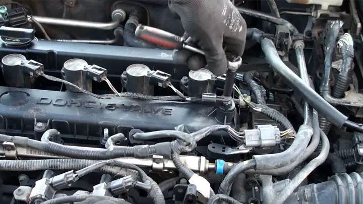
Check connector on camshaft sensor. Look for corrosion and bent pins. Apply dielectric grease to pins.
Check starter for excessive draw indicating a weak starter.
Replace “B” camshaft position sensor on bank 2

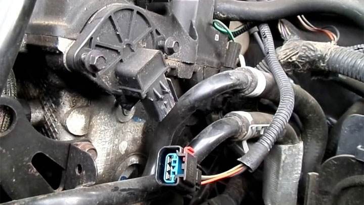
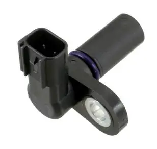
Example photo of a camshaft position sensor (CMP):

Related camshaft fault codes: P0340, P0341, P0342, P0343, P0345, P0346, P0347, P0348, P0349, P0365, P0366, P0367, P0368, P0369, P0390, P0391, P0393, P0394.

P0393 Low Input in Camshaft Position Sensor “B” Circuit, Bank 2

What does it mean?

This is a generic powertrain diagnostic trouble code (DTC), meaning it covers all makes/models from 2003 onward. The code appears more common on Kia, Hyundai, Chevrolet, Toyota, and Ford vehicles, but any brand vehicle can be affected.

Specific troubleshooting steps vary by vehicle.

These vehicles may have a single in-block camshaft or a single overhead camshaft (SOHC) or dual (DOHC), but this code is strictly concerned with the incoming signal from the Bank 1 ‘B’ camshaft position sensor(s) being missing, typically during engine startup. It is an electrical circuit fault. Bank #2 is the engine bank that does not contain cylinder #1.

The PCM uses the camshaft position sensor to tell it when the crankshaft sensor signal is correct, when a given crankshaft position sensor signal is timed to cylinder #1 for timing, and it is also used for the timing/start of fuel injector fuel injection.

P0390 or P0391 codes may also be present alongside P0393. The only difference between these 3 codes is the duration of the issue and the type of electrical problem encountered by the sensor/circuit/engine controller. Troubleshooting steps may vary by manufacturer, camshaft position sensor type, and wire colors.

Symptoms

Symptoms of a P0393 engine code may include:

Check Engine Light illuminated
Engine misfiring or surging
Stalls, but may restart if the issue is intermittent
May run fine until restarted; will not restart

Potential Causes

Typically, causes for this code are:

Open in the ground circuit for the Bank 2 ‘B’ camshaft position sensor
Open in the signal circuit between the ‘B’ camshaft position sensor and the PCM
Short to 5 volts in the camshaft position sensor signal circuit
Faulty camshaft position sensor – internal short to voltage

Diagnostic and Repair Procedures

A good starting point is always checking for a Technical Service Bulletin (TSB) for your specific vehicle. The vehicle manufacturer may have a PCM flash/reprogram to address this issue, and it’s worth checking before discovering you’ve taken a long/wrong path.

Next, locate the camshaft and crankshaft position sensors on your specific vehicle. Since they share common power and ground circuits, and this code focuses on the camshaft position sensor’s power and ground circuits, it makes sense to check them for any damage to either. Once located, visually inspect the connectors and wiring. Look for chafing, rubbing, bare wires, burns, or melted plastic. Disconnect the connectors and carefully inspect the terminals (the metal parts) inside the connectors. See if they appear corroded, burnt, or perhaps greenish compared to the normal metal color you’re used to seeing. You can get electrical contact cleaner at any auto parts store if terminal cleaning is needed. If not available, find 91% isopropyl alcohol and a soft plastic-bristled brush to clean them. Then, let them air dry, get some dielectric silicone compound (same as used for bulb sockets and spark plug wires), and apply a small amount where the terminals make contact.

If you have a scan tool, clear the diagnostic codes from memory and see if this code returns. If not, the connections were likely your problem.

If the code returns, we’ll need to test the sensor and its associated circuits. There are generally 2 types of camshaft position sensors: Hall effect or magnetic pickup sensor. You can usually tell which you have based on the number of wires from the sensor. If there are 3 wires from the sensor, it’s a Hall effect sensor. If it has 2 wires, it will be a magnetic pickup type sensor.

This code will only set if the sensor is a Hall effect sensor. Disconnect the harness going to the camshaft position sensor. With a digital volt-ohm meter (DVOM), test the 5V power circuit going to the sensor to ensure it has power (red lead to the 5V/12V power circuit, black lead to a good ground). Check with a wiring diagram or diagnostic chart whether this sensor is supplied with 5 volts or 12 volts. If there are 12 volts at the sensor when there should be 5 volts, repair the wiring from the PCM to the sensor for a short to 12 volts, or possibly a faulty PCM.

If that’s okay, with a DVOM, check that the camshaft position sensor signal circuit has 5V (red lead to the sensor signal circuit, black lead to a good ground). If there is no 5 volts at the sensor, or if you see 12 volts at the sensor, repair the wiring from the PCM to the sensor, or again a faulty PCM.

If that checks out, verify you have a good ground at each sensor. Connect a test light to the positive 12V battery terminal (red clip) and touch the other end of the test light to the ground circuit going to the camshaft sensor circuit ground. If the test light does not illuminate, that would indicate the circuit problem. If it lights up, wiggle the wire harness going to each sensor to see if the test light flickers, indicating an intermittent connection.

Related camshaft fault codes: P0340, P0341, P0342, P0343, P0345, P0346, P0347, P0348, P0349, P0365, P0366, P0367, P0368, P0369, P0390, P0391, P0392, P0394.

P0394 Camshaft Position Sensor “B”, Intermittent Circuit, Bank 2

What does it mean?

This is a generic powertrain diagnostic trouble code (DTC), meaning it covers all makes/models from 2003 onward. Specific troubleshooting steps vary by vehicle.

These vehicles may have a single block camshaft or a single overhead camshaft (SOHC) or dual (DOHC), but this code is strictly concerned with the incoming signal from the Bank 2 “B” camshaft position sensor(s) missing at some point when it shouldn’t be. It’s an electrical circuit fault and is intermittent in nature. It’s not present all the time. Bank #2 is the engine bank that does not contain cylinder #1.

The PCM uses the camshaft position sensor to tell it when the crankshaft sensor signal is correct, when a given crankshaft position sensor signal is timed to cylinder #1 for timing, and it is also used for the timing/start of fuel injector injection.

P0390 or P0391 codes may also be present along with P0394. The only difference between these 3 codes is the duration of the issue and the type of electrical problem encountered by the sensor/circuit/engine controller. Troubleshooting steps may vary by manufacturer, camshaft position sensor type, and wire colors.

Symptoms

Symptoms of a P0394 engine code may include:

Check Engine Light illuminated
Intermittent misfiring or surging
Intermittently stalls, but restarts immediately

Potential Causes

Typically, causes for this code are:

Intermittent open in the “B” camshaft position sensor power circuit
Intermittent short to ground in the “B” camshaft position sensor power circuit
Intermittent open in the “B” camshaft position sensor ground circuit
Intermittent open in the camshaft position sensor signal circuit
Intermittent short to 5 volts in the camshaft position sensor signal circuit
Intermittent short to ground in the camshaft position sensor signal circuit
Damaged camshaft position sensor tone ring
Crankshaft position sensor occasionally producing intermittent signals

Diagnostic and Repair Procedures

A good starting point is always searching for a Technical Service Bulletin (TSB) for your specific vehicle. The vehicle manufacturer may have a PCM flash/reprogram to cover this issue, and it’s worth checking before finding out you’ve taken a long/wrong path.

Next, locate the “B” camshaft position sensor and crankshaft position sensor on your specific vehicle. Once located, visually inspect the connectors and wiring. Look for chafing, rubbing, bare wires, burns, or melted plastic. Disconnect the connectors and carefully inspect the terminals (the metal parts) inside the connectors. See if they look corroded, burnt, or perhaps greenish compared to the normal metallic color you’re probably used to seeing. You can get electrical contact cleaner at any auto parts store if terminal cleaning is needed. If not possible, find 91% isopropyl alcohol and a soft plastic-bristled brush to clean them. Then let them air dry, get some dielectric silicone compound (same as used for light bulb sockets and spark plug wires) and apply a small amount where the terminals make contact.

If you have a scan tool, clear the diagnostic codes from memory and see if this code returns. If not, the connections were likely your problem.

If the code returns, we’ll need to test the sensor and its associated circuits. The next steps will be determined by the type of sensor you have: Hall effect or magnetic sensor. You can usually tell which you have based on the number of wires coming from the sensor. If there are 3 wires from the sensor, it’s a Hall effect sensor. If it has 2 wires, it will be a magnetic pickup type sensor.
Hall Effect Sensor

If it’s a Hall effect sensor, disconnect the harness going to the camshaft and crankshaft position sensors. With a digital voltmeter (DVOM), test the 5V power circuit going to each sensor to ensure it has power (red wire to 5V power circuit, black wire to a good ground). If there’s no 5 volts at the sensor, repair the wiring from the PCM to the sensor, or possibly a faulty PCM.

If that’s okay, with a DVOM, check that you have 5V on each signal circuit going to each sensor to ensure it has a signal circuit (red wire to sensor signal circuit, black wire to a good ground). If there’s no 5 volts at the sensor, repair the wiring from the PCM to the sensor, or possibly a faulty PCM.

If that’s okay, verify you have a good ground at each sensor. Connect a 12V test light and touch the other end of the test light to the ground circuit going to each sensor. If the test light doesn’t illuminate, that would indicate the circuit problem. If it lights up, wiggle the wire harness going to each sensor to see if the test light flickers, indicating an intermittent connection.

Magnetic Pickup Sensor

If it’s a magnetic pickup type sensor, we can check the sensor itself to see if it’s working properly. We’ll test it for:

Resistance
A/C voltage output
Short to ground

With the sensor disconnected, connect both wires of your ohmmeter to the 2 terminals of the camshaft/crankshaft position sensor. Read the ohms resistance and compare it to your vehicle’s specifications: typically 750 – 2000 ohms. While still on ohms, disconnect 1 wire of your ohmmeter from the sensor and connect it to a good vehicle ground. If you get an ohms reading other than infinite or OL, the sensor has an internal short to ground. Remember not to touch the metal part of the wires with your fingers, as this could affect your readings.

Reconnect both wires of your DVOM to the 2 terminals of the camshaft/crankshaft position sensor. Set your meter to read A/C voltage. While cranking the engine, read the a/c voltage output on your DVOM. Compare to the manufacturer’s specifications for your vehicle. A good rule of thumb is typically 0.5 V AC.

Related camshaft fault codes: P0340, P0341, P0342, P0343, P0345, P0346, P0347, P0348, P0394, P0365, P0366, P0367, P0368, P0369, P0390, P0391, P0392, P0393.

P0395 – P03FF ISO/SAE Reserved

P00C0 – P00FF ISO/SAE Reserved

P0344 Code (Symptoms, Causes, and How to Fix It)

This formidable engine control unit strikes fear into the hearts of drivers worldwide. But don’t panic when a P0344 code is the result. Although it sounds alarming, this trouble code is often caused by minor issues.

Let’s explore the meaning and common culprits behind the P0344 code and how to get your engine running again without breaking the bank.

What Does Code P0344 Mean?

OBD-II Trouble Code P0344 Description
Intermittent Camshaft Position Sensor “A” Circuit (Bank 1)

The P0344 diagnostic trouble code alludes to a detected lack of stability in the camshaft position sensor’s return signal. Simply put, the vehicle’s ECM/PCM has determined that the return signal from its corresponding camshaft position sensor is erratic or intermittent.

This, in turn, compromises the ECM/PCM’s ability to use this sensor’s anticipated feedback to formulate further engine strategy.

To better understand the complexities of the P0344 diagnostic trouble code, it’s best to first familiarize yourself with the role of the camshaft position sensor in modern engine operation.

Camshaft Position Sensor

Today’s electronically monitored engines rely heavily on data from a number of sensors to formulate engine operating strategy, and few of these sensors are as critical as those related to engine timing, with the camshaft position sensor being the most precise of these sensors.

Without valid feedback from an engine’s camshaft position sensor, a vehicle’s ECM/PCM is unable to accurately determine proper fuel injection timing, as no high-end timing measurements are retained or recorded. Furthermore, other engine functions, such as variable valve timing, are also canceled.

In the case of DTC P0344, a vehicle’s operating software momentarily loses connection with the engine’s camshaft position sensor, thereby failing to execute several timing-sensitive functions as it otherwise would.

As a result, a number of serious drivability-related symptoms often appear, including timing/starting difficulties.

Symptoms of Code P0344

The P0344 diagnostic trouble code is often accompanied by a number of secondary symptoms, some of which tend to be quite alarming in nature. Recognizing such symptoms will be advantageous when it comes to diagnosing and repairing an issue.

Here are some of the most common symptoms associated with DTC P0344.

  • Check Engine Light illuminated
  • Intermittent rough idle
  • Hesitation under load
  • Unexplained stalling

Causes of Code P0344

The P0344 diagnostic trouble code can be triggered by any one of several underlying issues, some of which often prove more difficult to identify than others. As in all cases, understanding the potential causes of such a problem can make all the difference when attempting to perform a timely repair.

Here are some of the most common causes of DTC P0344:

  • Open/shorted cam sensor power circuit
  • Open/shorted cam sensor ground circuit
  • Open/shorted cam sensor return circuit
  • Faulty camshaft position sensor
  • Damaged camshaft tone ring

Is Code P0344 Serious?

Generally speaking, the P0344 diagnostic trouble code is considered by most to be rather serious in nature. This is largely due to the many drivability-related symptoms that often accompany faults of this nature.

Any issue that could potentially leave you and your vehicle stranded is not a problem to be taken lightly or overlooked.

Intermittent hesitation and stalling are both potential symptoms of an active P0344 diagnostic trouble code. Continuing to drive with your vehicle in such a condition can pose a serious risk to persons and property, should your vehicle stall unexpectedly in traffic (especially at highway speeds).

In all cases, the cause of a vehicle’s P0344 diagnostic trouble code should be thoroughly diagnosed and repaired at the first available opportunity. This is the only reliable way to ensure that your car operates safely and effectively.

If you do not feel comfortable performing the repairs yourself, schedule an appointment with a trusted automotive repair shop or dealership at your earliest convenience.

How to Fix Code P0344

The following steps can be used to assist you in diagnosing and repairing the root cause of your vehicle’s P0344 trouble code. As always, a factory-specific manual (such as Haynes, Chilton, or an online source) should be consulted for your particular vehicle model before attempting such repairs.

#1 – Check for Additional DTCs

Before beginning the diagnostic process, it is important to check for any potential additional DTCs. Any detected DTCs should be thoroughly diagnosed before proceeding.

#2 – Inspect the Camshaft Position Sensor

One should begin by carefully inspecting their engine’s camshaft position sensor for any signs of excessive stress or damage. Any obvious damage to the camshaft position sensor itself will require replacement.

Likewise, any damage to the sensor’s wiring harness should be repaired or replaced immediately.

#3 – Analyze Freeze Frame Data

Next, display all freeze frame data associated with the storage of the P0344 DTC. Determine the number of times the camshaft sensor’s return signal was interrupted, as well as how frequently such failures occur.

Likewise, you should attempt to determine any common denominators, in terms of recorded data, that might help isolate the cause of this fault.

#4 – Determine Sensor Type

At this point, further diagnosis will require you to identify the type of camshaft sensor with which your vehicle is equipped.

If your vehicle’s camshaft position sensor is equipped with 2 wires, it is a magnetic sensor. If this sensor has 3 wires, it is a Hall effect sensor.

#5 – Testing Magnetic Sensors

If your vehicle’s camshaft position sensor is of a magnetic sensor configuration, resistance should be checked across both terminals of this sensor itself with it disconnected. This resistance reading should be compared to the figures specified by your vehicle’s manufacturer.

Additionally, these two terminals should also be probed while an assistant attempts to crank the engine in question, with your meter set to A/C volts. Again, this reading should be compared to manufacturer specifications, although 0.5 V AC is generally satisfactory.

#6 – Test the Hall Effect Sensor

If your vehicle’s camshaft position sensor is of the Hall effect type, a multimeter should be used to test the corresponding wiring harness to ensure that a power source (5V) and a satisfactory ground are present.

If both values are present at the sensor itself, live data derived from your OBD2 scan tool should be consulted to verify that appropriate feedback is being provided to the PCM.

Code P0328 (Symptoms, Causes, and How to Fix It)

Has your vehicle recently been faced with a bothersome check engine light, caused by an active P0328 fault? If so, you’re probably asking yourself many questions about the meaning of this fault and how to proceed.

Continue reading to find out exactly what a P0328 code means, its probable causes, its severity, and most importantly, how to fix it.

What does the P0328 code mean?

OBD-II Trouble Code P0328 Description

Knock Sensor 1 – Circuit High Input (Single Sensor or Bank 1)

The P0328 diagnostic trouble code indicates a high input voltage condition present in a vehicle’s knock sensor circuit. In the case of this specific DTC, the fault in question refers to the Bank 1 knock sensor, if the vehicle in question is equipped with a “V” configuration engine.

This feedback indicates a general anomaly within this sensor’s monitoring circuit, calling into question the accuracy of the monitoring.

To better understand this principle, one must first understand how a knock sensor works. Generally speaking, the knock sensor is designed to detect pre-ignition “ping” or “knock,” thereby allowing for spark timing retardation in response.

Sensors of this type also tend to detect other acoustic anomalies, such as those associated with rod knock or piston slap.

In the case of DTC P0328, the vehicle’s ECU has determined that the input voltage from the Bank 1 knock sensor has exceeded its intended operating threshold.

Most knock sensors operate on a 5-volt reference circuit, meaning the out-of-spec voltage in question would have remained in the high end of this spectrum for a prolonged period.

The P0328 diagnostic trouble code, in itself, does not solely indicate a faulty knock sensor, nor an actual pre-ignition event, although the possibility of either should not be overlooked.

In many cases, a short circuit condition is actually responsible for a fault of this nature, which places increased importance on meticulously checking the integrity of the related circuit.

Symptoms of the P0328 Code

The P0328 trouble code is often accompanied by a multitude of secondary symptoms, a few of which can be quite noticeable. Recognizing these signs often proves essential when attempting to speed up the overall diagnostic and repair process.

Here are some of the most common symptoms associated with DTC P0328.

  • Illuminated Check Engine Light
  • Abnormal Engine Noises (Knocking/Rattling)
  • Reduced Engine Performance
  • Irregular Idle

Causes of the P0328 Code

The P0328 diagnostic trouble code can be caused by one of several underlying issues, some of which tend to be easier to isolate than others. Understanding these potential causes can save time and effort when attempting to establish a solid diagnosis.

Here are some of the most common causes of a P0328 code.

  • Faulty Knock Sensor
  • Damaged Knock Sensor Circuit Wiring
  • Interference in the Knock Sensor Signal
  • Fuel with Poor Octane Rating
  • Incorrect Fuel Pressures
  • Internal Engine Damage
  • PCM Failure

Is the P0328 Code Serious?

The P0328 diagnostic trouble code is generally considered to be rather serious in nature, due to some of the potential underlying problems that such a fault often signifies.

In the “best-case scenario,” the vehicle’s knock sensor might simply be faulty, or the electrical circuit for this sensor could be compromised. On the other hand, however, actual knock could truly exist, indicating a much more severe condition.

Even if the detected “knock” or “ping” is strictly the product of pre-ignition, prolonged operation in this state can eventually lead to accelerated engine wear or engine damage.

This stems from the simple fact that pre-ignition indicates combustion that is not ideal or optimally efficient. This, in turn, places excessive stress on a number of internal engine components.

In any case, the root cause of a vehicle’s P0328 trouble code must be carefully diagnosed and repaired as soon as possible. This will most likely prevent further engine damage. If you do not feel comfortable performing such repairs yourself, schedule an appointment with a trusted automotive service center at your earliest convenience.

Regardless of the specifics, diagnosing and resolving the underlying issue causing the P0328 trouble code in your vehicle should be a top priority. Taking prompt action can help prevent any risk of engine damage.

If you lack the necessary skills or tools to resolve this issue yourself, schedule an appointment with a reputable repair shop as soon as possible.

How to Fix the P0328 Code

You can identify and resolve the issue triggering the P0328 code in your car by following these troubleshooting steps. But before performing any repairs yourself, always consult the factory service manual for your exact make and model.

#1 – Check for Additional DTCs

Before beginning the diagnostic process, use a scan tool to check for any additional DTCs. All logged codes should be carefully diagnosed before continuing.

#2 – Inspect the Knock Sensor/Mounting

Start by carefully inspecting your vehicle’s knock sensor for any signs of damage. Likewise, the knock sensor itself should be checked for proper mounting and mounting tightness before continuing.

#3 – Check Wiring Condition

Next, all wiring related to the affected knock sensor should be carefully inspected for any signs of damage. Along the same lines, the knock sensor connector should be checked to ensure it is tight and free of corrosion.

#4 – Check Engine Integrity

At this point, it will be necessary to verify that your vehicle’s engine has not suffered any type of internal mechanical failure. Check engine coolant and oil levels by carefully checking for mixing of these two fluids.

Next, start the engine, revving it several times while listening carefully for abnormal noises. Any abnormal noise heard should be thoroughly investigated.

#5 – Check Freeze Frame Data

If no other issues are apparent, analyze the freeze frame data related to this fault. Check all knock sensor-related PIDs for obvious irregularities. If possible, replicate the conditions represented.

#6 – Test the Knock Sensor with a Meter

Although directly testing a knock sensor can be tricky, a few tests can be performed to check the sensor’s general functionality.

A multimeter can be used to measure between the 2 wires connected to this sensor while checking for continuity. A lack of continuity would indicate a faulty sensor.

Furthermore, these two wires can be back-probed and checked individually with the positive lead of a multimeter, while grounding them to a reliable ground. Ideally, the output of such a sensor should be between 0V and 4.9V.

P0300 Code Chevrolet – Engine Misfire Detected

What are the possible causes of Chevrolet DTC P0300?

NOTE: The listed causes may not be a complete list of all potential issues, and there could be other causes.

Possible Causes

  • Faulty spark plug(s)
  • Faulty ignition coil(s)
  • Clogged or faulty fuel injector(s)
  • Intake air leak
  • Fuel injector harness is open or shorted
  • Poor electrical connection in the fuel injector circuit
  • Ignition coil harness is open or shorted
  • Poor electrical connection in the ignition coil circuit
  • Insufficient cylinder compression
  • Incorrect fuel pressure

How to fix Chevrolet DTC P0300?

Review the Possible Causes mentioned above and visually inspect the corresponding wiring harness and connectors. Make sure to check for any damaged components and inspect the connector pins for signs of breakage, bending, push-out, or corrosion.

Code P0300 – Chevrolet Technical Notes

Code P0300 indicates that one or more cylinders are misfiring or experiencing random misfires.

Diagnostic Steps

  1. Check for intake leaks; intake gaskets are a common cause of multi-cylinder misfires.
  2. If no leaks are found, the next step is to replace the spark plugs.
  3. If the problem persists, further testing is required to diagnose the issue (see “Possible Causes”).

Diagnosing 2002 Chevrolet Blazer P0300 Misfires

What are the possible symptoms of Chevrolet code P0300?

  • Check Engine Light on (or Engine Maintenance Warning Light soon)
  • Lack/loss of power
  • Hard starting
  • Engine hesitation

Chevrolet Code P0300 – Description

A misfiring cylinder causes slight variations in crankshaft rotation speed. The Engine Control Module (ECM) can detect these variations by closely monitoring the signal from the crankshaft position sensor.

System Operation

  • Camshaft position sensors are used to determine which cylinder is misfiring.
  • If the ECM detects a misfire rate sufficient to cause emission levels to exceed mandatory standards, a Diagnostic Trouble Code (DTC) will be set.
  • Under certain driving conditions, a misfire rate may be high enough to cause the catalytic converter to overheat, potentially damaging it.
  • The Malfunction Indicator Lamp (MIL) flashes when the converter overheats and damaging conditions are present.

DTC Triggering Conditions

The DTC will be set when the ECM detects:

  • A variation in crankshaft rotation speed indicating a misfire rate sufficient to cause emission levels to exceed a predetermined value.
  • A misfire rate high enough to damage the catalyst.

What is OBD?

OBD stands for On-Board Diagnostics. OBD-II (OBD two) is the latest industry standard, introduced in 1996 vehicle models. It monitors nearly all engine controls, as well as some other vehicle components (chassis, body, etc.).

The most useful aspect of OBD for most drivers is the ability to read vehicle information. You can read fault codes and even monitor real-time statistics such as RPM, vehicle speed, etc.

Explanation of OBD2 Codes

OBD-II codes consist of several parts. Here is an example of an OBD2 code:

P0131

Here is an explanation of what each digit in the code means:
First character – System

The first character identifies the system related to the fault code.

     P = Powertrain
     B = Body
     C = Chassis
     U = Undefined


Second digit – Code type

The second digit identifies whether the code is a generic code (the same on all OBD-II equipped vehicles) or a manufacturer-specific code.

     0 = Generic (this is the digit zero – not the letter “O”)
     1 = Enhanced (manufacturer-specific)

Third digit – Subsystem

The third digit indicates the type of subsystem related to the code

     1 = Emissions management (fuel or air)
     2 = Injector circuit (fuel or air)
     3 = Ignition or misfire
     4 = Emissions control
     5 = Vehicle speed and idle control
     6 = Computer and output circuit
     7 = Transmission
     8 = Transmission
     9 = SAE reserved
     0 = SAE reserved

Do I have an OBD-II vehicle?

Some vehicles from model years 1994 and 1995 have OBD-II. If your vehicle is from 1996 or newer, U.S. federal law requires all cars and light trucks sold in North America to be OBD-II compliant. This includes all domestic vehicles (Ford, Dodge, GM, etc.) and imported/foreign vehicles (Toyota, Honda, etc.).

The foolproof way to know if your vehicle is OBD-II compatible is to look for the standard DLC (data link connector) that all OBD II vehicles have. It looks like this (16-pin connector) and will typically be located under the driver’s side of the dashboard:

Other possible DLC connector locations include:

     Behind a removable trim on or under the dashboard
     Near the gear shift
     Inside the center console next to the driver (seen on a Volvo, you need to open the console cover to access it)
     Under the passenger side of the dashboard (seen on a Ford Thunderbird)

Now, if your vehicle is 1996 or newer, you definitely have OBD-II. If your vehicle is older than 1996, the presence of the DLC may or may not indicate that you have OBD-II. To check, look under the hood for a VECI label. The VECI label will indicate whether the vehicle is equipped with OBD II or not. Sorry, we don’t have a photo of the VECI label.

We found a very helpful service that locates the DLC (data link connector) for your vehicle; you can either enter your VIN or year/make/model, go to the Innova DLC search tool.