What does it mean?
This is a generic diagnostic trouble code (DTC) and applies to many OBD-II vehicles (1996-newer). This may include, but is not limited to, vehicles from Nissan, Toyota, Mazda, Hyundai, Kia, etc. Although generic, the exact repair steps may vary depending on the year, make, model, and powertrain configuration.
If your OBD-II equipped vehicle has stored a P063F code, it means that the Powertrain Control Module (PCM) has not detected an engine coolant temperature input signal for automatic configuration.
When the ignition is turned to the ON position and the various onboard controllers (including the PCM) are powered up, several self-tests are initiated. The PCM relies on input signals from engine sensors to automatically configure an engine start-up strategy and perform these self-tests. The engine coolant temperature is one of the primary input signals required by the PCM for automatic configuration.
The Engine Coolant Temperature (ECT) sensor must provide the PCM (and other controllers) with an engine coolant temperature input signal for automatic configuration purposes. The ECT is a sensor made of brass, steel, or plastic with a thermistor (suspended in resin) inside its tip. The ECT is typically threaded into an engine coolant passage so that the tip is inserted into the passage. Engine coolant flows over the sensor’s tip and affects the thermistor inside. When the engine coolant warms up, the ECT sensor’s resistance decreases and the circuit voltage increases. When the engine coolant temperature decreases, the ECT sensor’s resistance increases and the circuit voltage decreases.
If the PCM fails to detect an ECT sensor input circuit when the ignition switch is turned to the ON position and the PCM is powered up, a P063F code will be stored, and a Malfunction Indicator Lamp may illuminate. The automatic configuration system may also be disabled, leading to severe driveability issues.
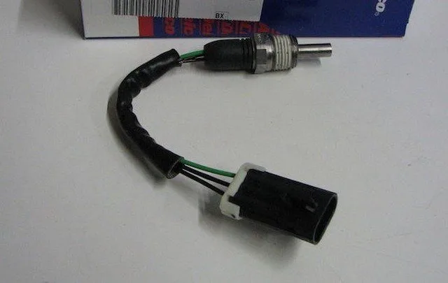
A typical engine coolant temperature sensor:
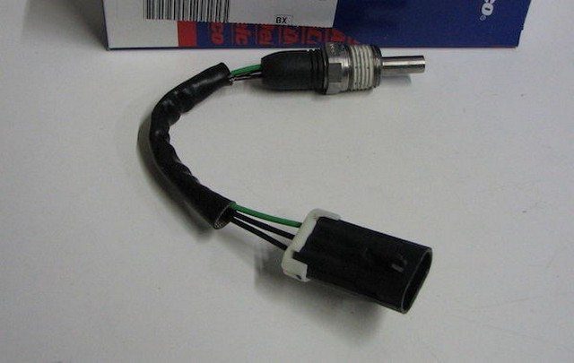
P063F Coolant Temperature Sensor
How severe is this DTC?
Automatic configuration codes should be taken seriously as engine idle quality and start-up driveability can be compromised. Classify a stored P063F code as severe and address it as such.
What are some of the symptoms of the code?
Symptoms of a P063F trouble code may include:
- Rough engine idle (especially at start-up)
- Delayed engine starting
- Driveability issues
- Other ECT-related codes
What are some common causes of the code?
Causes
of this code may include:
- Faulty ECT sensor
- Open or shorted circuit between the ECT sensor and the PCM
- Corrosion in the ECT connector
- PCM programming error or incorrect PCM
What are the P063F troubleshooting steps?
If other ECT-related codes are present, diagnose and repair them before attempting to diagnose P063F. Also, ensure the engine is filled with the proper coolant and is not overheating before testing.
A diagnostic scanner, a digital volt/ohmmeter (DVOM), an infrared thermometer with a laser pointer, and a reliable source of vehicle information will be necessary to accurately diagnose a P063F code.
Consult your vehicle information source for applicable Technical Service Bulletins (TSBs). If you find one that matches the vehicle, symptoms, and codes you are dealing with, it may help in making a correct diagnosis.
I always begin any code diagnosis by connecting the scanner to the vehicle’s diagnostic port and retrieving all stored codes and relevant freeze frame data. I like to note this information (or print it if possible) in case I need it later (once the codes are cleared). Then, I clear the codes and test-drive the vehicle until one of two scenarios occurs:
A. The code does not reset and the PCM enters a ready state
B. The code resets
If scenario A occurs, you are dealing with an intermittent code, and the conditions that caused it may need to worsen before an accurate diagnosis can be made.
If scenario B occurs, proceed to the steps listed below.
Step 1
Perform a visual inspection of all associated wiring and connectors. Check the PCM power fuses and relays. Perform necessary repairs. If no issues are detected, proceed to the next step.
Step 2
Obtain diagnostic flowcharts, wiring diagrams, connector face views, connector pinout diagrams, and component test specifications/procedures from your vehicle information source.
Once you have the correct information, use the DVOM to test the ECT voltage, ground, and signal circuits.
Step 3
Start with a simple test for voltage (typically 5 volts) and ground signals at the ECT connector. If there is no voltage, use the DVOM to trace the circuit back to the appropriate terminal on the PCM connector. If there is no voltage at that pin, suspect a faulty PCM. If there is voltage at the PCM connector pin, repair the open circuit between the PCM and the ECT sensor. If there is no ground, trace the circuit to the central ground location and perform necessary repairs. If ground and voltage are found at the ECT connector, proceed to the next step.
Step 4
Use the infrared thermometer to determine the actual engine coolant temperature. The scanner data stream will reveal what temperature (or voltage level) is being input to the PCM (if any). Compare the voltage-to-temperature information (found in your vehicle information source) to determine if the ECT sensor is functioning normally.
If the ECT sensor and all system circuits are functional, suspect a faulty PCM or a PCM programming error.
Many OBD-II equipped vehicles use multiple ECT sensors. One may be for the dashboard gauge and another for the PCM. Use your vehicle information source to ensure you are testing the correct ECT sensor.