What Does It Mean?
This diagnostic trouble code (DTC) is a generic powertrain code, meaning it applies to all vehicles from 1996 onwards (Chevy, Chevrolet, Isuzu, Cadillac, Subaru, Saab, Volvo, GMC, GM, etc.). Although generic, specific repair steps may vary by make/model.
A stored P0502 code means the Powertrain Control Module (PCM) has detected a low voltage input signal from the Vehicle Speed Sensor (VSS) A. The A designation typically refers to the primary VSS in systems that use multiple vehicle speed sensors.
Most vehicle speed sensors are electromagnetic sensors that use some type of toothed reluctor ring or gear permanently attached to an axle, transmission/transfer case output shaft, differential gear, or driveshaft. As the shaft rotates, so does the reluctor device, which completes a circuit with the stationary electromagnetic sensor. When the reluctor passes very close to the sensor’s electromagnetic tip, the notches in the reluctor ring create interruptions in the sensor’s circuit. The combination of circuit completions and interruptions is received by the PCM (and other controllers) as waveforms representing voltage.
The PCM monitors vehicle speed using input data from one or more vehicle speed sensors and compares it to inputs from the Anti-lock Brake Control Module (ABCM) or Electronic Brake Control Module (EBCM). In some cases, the secondary VSS input may be monitored using one or more wheel speed sensors, but the primary (A) VSS input will likely be initiated by the VSS in the transmission.
If the PCM detects a low input voltage signal from the primary VSS, a P0502 code will be stored, and a malfunction indicator lamp may illuminate. A low voltage input condition can be caused by an electrical or mechanical issue.
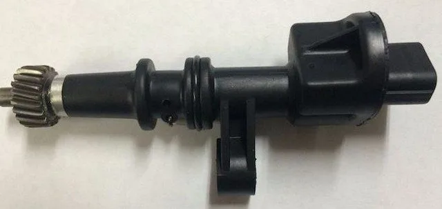
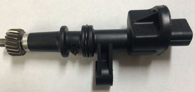
A typical VSS or vehicle speed sensor:
Related vehicle speed sensor trouble codes:
P0500 Vehicle Speed Sensor “A” Malfunction
P0501 Vehicle Speed Sensor “A” Range/Performance
P0503 Vehicle Speed Sensor “A” Intermittent/Erratic/High
Code Severity and Symptoms
Since conditions that can lead to storing a P0502 code may create driving and ABS problems, it should be classified as severe and addressed as soon as possible.
Symptoms of a P0502 code may include:
Erratic speedometer/odometer operation
Irregular transmission shifting patterns
Illumination of the Check Engine Light, traction control light, or anti-lock brake light
Unexpected activation/deactivation of the traction control system (if equipped)
Other transmission and ABS codes may be stored
The ABS system may be rendered inoperative in some cases
Causes
Possible causes of this code include:
Excessive buildup of metallic debris on speed sensors
A faulty wheel speed sensor or vehicle speed sensor
Cut or damaged wiring harnesses or connectors (especially near speed sensors)
Damaged or worn teeth on a reluctor ring
Faulty PCM, ABCM, or EBCM
Diagnostic and Repair Procedures
A diagnostic scanner, a digital volt/ohmmeter (DVOM), possibly an oscilloscope, and a reliable source of vehicle information will be needed when diagnosing a P0502 code.
I normally like to start my diagnosis of a P0502 with a visual inspection of the system wiring, speed sensors, and connectors. Repair open or shorted circuits as needed and clean excessive metallic debris from affected sensors. Check the integrity of the reluctor ring when inspecting the sensor.
Connect the scanner to the vehicle’s diagnostic port and retrieve all stored trouble codes and available freeze frame data. Before clearing the codes, note this information as it may prove useful as your diagnosis progresses.
Using your vehicle information source, research applicable Technical Service Bulletins (TSBs). If you find a TSB that matches the symptoms and stored codes of the vehicle in question, the diagnostic information it contains will likely help diagnose the P0502 from here.
Use the scanner’s data stream to observe wheel speed and vehicle speed during a vehicle road test. You can restrict the data stream to display only relevant fields to increase the speed and accuracy of the desired data delivery. Inconsistent or erratic readings from VSS or wheel speed sensors can lead you to wiring, electrical connector, or sensor issues by narrowing down the general area of the system malfunction.
After locating the VSS circuit from which the low voltage input is initiated, use the DVOM to perform a resistance test on the sensor in question. Consult your vehicle information source for the manufacturer’s recommendations regarding VSS testing and replace sensors that do not meet specifications.
Use the oscilloscope to retrieve live data from each individual VSS by probing the sensor signal wire and the sensor ground wire. Jacking up or lifting the vehicle will almost always be necessary to perform this type of test correctly. Once the drive axle(s) are securely fixed to the ground, run the transmission while observing the waveform on the oscilloscope. Focus on glitches or inconsistencies in the pattern and proceed with diagnosis accordingly.
Vehicle speed sensors can be damaged during routine maintenance, while wheel speed sensors and sensor wiring harnesses are frequently damaged during brake repairs. If this code appears immediately after a repair, suspect a damaged sensor harness, connector, or sensor.
Additional Diagnostic Notes:
When performing circuit resistance and continuity tests with a DVOM, always disconnect the electrical connectors from the associated controllers – failure to do so could result in a damaged controller
Be cautious when removing sensors from transmission housings as hot transmission fluid may be inadvertently released