To understand shift solenoid symptoms, it’s important to understand why and how automatic transmissions shifted BEFORE there were solenoids, and why solenoids were added to begin with.
How Planetary Gears Work
Transmissions and transaxles that shift automatically (CVT units not included) have one or more planetary gearsets at the heart of the unit. These gearsets, along with driving and holding elements such as brakes and clutches, provide the different gear ranges, including reverse.
A simple planetary gearset consists of a sun gear, a planet carrier with several small planet gears that rotate around that sun gear, and a ring gear that surrounds the outside of the planet gears.
If you hold the planet carrier and drive the sun gear, the ring gear is driven in the opposite direction. That’s reverse.
Holding the sun gear and driving the ring gear drives the planet carrier to provide a gear reduction ratio, and holding the ring gear while driving the planet carrier spins the sun gear as the output to provide a different gear reduction ratio, and so on.
Power from the engine is transferred via the torque converter, which has an impeller integrated into the torque converter shell and a turbine with matching blades attached to the shaft that drives the guts of the transmission.
Any part of the planetary gearset can be held or driven. Clutches inside rotating drums are applied hydraulically by a piston inside the drum. “Brake clutch” packs or static bands attached to the outside of the transmission and applied by hydraulic pistons act as “holding” elements.
There are also one-way clutches that are applied mechanically by the direction of the rotating elements.
The Hydraulics of a Transmission
The hydraulic element of a transmission starts with the suction of fluid from the pan through the filter to the pump, which is driven by the outer shell of the torque converter. This shell is bolted to the engine’s “flexplate,” which is, at its center, bolted to the crankshaft.
It’s called a “flexplate” because as pressure builds in the torque converter, its shell expands, and since this shell is bolted to the outer edges of the flexplate, this plate must flex with the torque converter’s expansion. This is why automatic transmission flexplates sometimes crack around the center.
The hydraulic pressure created by the pump fills the torque converter and is available to the “valve body” as “line pressure.” This valve body is usually made of aluminum and is bolted to the transmission case with a plate sandwiched between two gaskets featuring many small holes.
The valve body is machined with a complex set of internal passages featuring spool valves and springs designed to direct hydraulic pressure to the various driving or holding elements that interact with the planetary gearset(s) that provide the different gear ranges.
Keep that thought – we’ll get to the solenoids in a minute.
How Older Transmissions Shifted
A “governor” with an internal spool valve was originally designed to spin faster as vehicle speed increased, and this governor would actuate its spool valve using centrifugal force.
As the spool valve inside the governor changes position with increasing vehicle speed, the fluid pressure passing through the governor is sent to other spool valves inside the valve body, moving them against spring pressure and redirecting fluid to the driving or holding elements.
It is necessary to hold each gear longer when the transmission shifts under heavy acceleration or when the vehicle is pulling a heavy load. This requires another pressure channel that opposes the governor pressure. This pressure is called “throttle valve” pressure.
On many older transmissions, there is a “modulator” valve with a movable core attached to an internal vacuum diaphragm inside the valve. The core moves a simple spring-loaded spool valve in the transmission.
The vacuum feeding this modulator valve comes directly from the intake manifold. When the engine is under load, vacuum decreases, the valve core moves its spool valve in the transmission to fight against the governor pressure.
When throttle valve pressure is high, governor pressure cannot cause the next shift in the sequence until vehicle speed (via the governor) increases governor pressure enough to overcome the throttle pressure, forcing the shift to occur, only later than it would have with lower throttle pressure.
Almost all transmissions began moving away from vacuum modulators to using throttle position (via a linkage or cable) to control throttle valve pressure. Chrysler transmissions never used vacuum modulators, unlike most other platforms.
Solenoids and Failure Symptoms
The first transmission solenoids were designed to control the “torque converter clutch,” a feature that began appearing in the late 1970s aimed at increasing fuel economy.
Most transmissions had 3 speeds and “Overdrive.” In third gear, the Torque Converter Clutch (TCC) would lock the torque converter shell to the turbine, causing a direct connection between the engine and the turbine shaft. When you press the brake, the torque converter clutch releases.
When the engine is cold, some vehicles do not allow torque converter lockup, as it generates heat while shearing the fluid when the TCC is unlocked, and transmission fluid needs to warm up quickly for optimal transmission operation.
These TCC solenoids can stick, keeping the torque converter engaged when the vehicle comes to a stop, causing the engine to stall. This is the first symptom we’ll mention that can be caused by a faulty solenoid.
If the solenoid fails to lock the TCC, fuel economy will suffer and the driver might not even realize the TCC isn’t locking, unless they are diligent about monitoring the tachometer.
Solenoids and Vehicle Computers
As computers became commonplace on vehicles in the late 1970s and early 1980s, engineers began giving computers control over more and more components.
Even though the valve body still functioned the same way, computer inputs and outputs were added. Pressure switches reported fluid pressure in various parts of the valve body. These early switches were simple on/off switches but were quickly replaced by one or more transducers indicating pressure.
Throttle valve pressure and what was once governor pressure both became elements of the computer-controlled transmission through the pulsed application of a special solenoid. Shift solenoids could be applied to force an increase in fluid pressure in certain parts of the valve body.
Engine load, vehicle speed, transmission input and output shaft speeds, and throttle position suddenly became the data that determined transmission pressures, shift points, and even the feel and quality of the shift. Many transmissions momentarily “decouple” the engine at the moment the transmission shifts to soften the shift feel.
Some Asian vehicles used “fuzzy logic” to prevent the transmission from downshifting while climbing shallow grades with cruise control activated. Performance packages began appearing with switches on the dashboard or shifter to alter the shift feel for those who liked sharp, hard shifts between gears.
Shift Solenoid Operation and Problems
Different transmissions have a different number of solenoids, and they don’t always operate in the order we might think. Sequential thinkers might logically believe that if a transmission has Solenoid A, Solenoid B, and Solenoid C, then Solenoid A would trigger the 1-2 shift, Solenoid B the 2-3 shift, and Solenoid C would trigger the 3-4 shift.
That’s not how it works.
You can look at a simple shift solenoid chart and see how complicated solenoid operation is between gears:
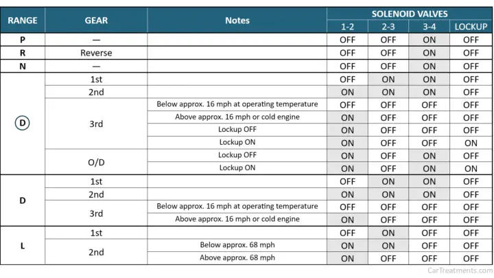
When solenoids fail, it depends on WHICH solenoid fails as to what results. A single shift solenoid can fail and affect multiple gear ranges (see the chart above). And not all symptoms are solenoid-related.
Solenoid-related DTCs will indicate the solenoid’s electrical circuit or a condition where there is nothing wrong with the circuit but the PCM or TCM has commanded the solenoid to act but determines from the input and output speed sensors that the commanded shift did not occur as commanded. This is classified as a “performance fault.”
Typically, when a solenoid fails, you will notice a difference in the feel or quality of the shift. The transmission might skip a gear, shift harshly, etc.
If power is lost to the transmission solenoids on newer vehicles, the pressure control solenoid will default to high pressure to prevent the clutches from slipping and destroying themselves, and the transmission will default to a higher gear than first gear.
But on earlier transmissions, the transmission solenoids were powered by a fuse, and if that fuse is removed or blows for any reason, the transmission will take off in first gear and never shift.
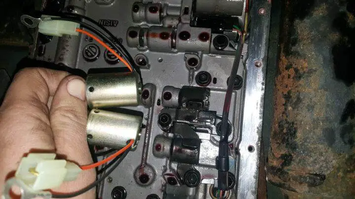
Where Are the Shift Solenoids Located?
Solenoids were initially mounted on the valve body as separate components, and most transmission shops would replace all solenoids when rebuilding a transmission (this is a good practice) to prevent solenoids from causing issues, as they often do.
Many transmissions and transaxles still have shift solenoids mounted directly on the valve body, but they are often sold in sets.
But on newer transmissions, solenoids are usually contained in a single “solenoid pack” that houses all the solenoids. This solenoid pack on some Chrysler transaxles is external and can be replaced without even removing the transmission oil pan, but most solenoid packs require draining the fluid to replace the solenoid pack, and in some cases, programming or a learning procedure may be required.
Some Honda transaxles typically have individual solenoids mounted externally.
Asian transaxles (like Nissans) typically ground their transmission solenoids and switch power to the solenoid from the PCM/TCM, but most other platforms power the solenoids whenever the key is on and control them by switching the ground.