The oxygen sensor (or lambda sensor) is a key component of the engine management system. It measures the amount of oxygen in the exhaust gases and sends this information to the PCM (Powertrain Control Module) to adjust the air/fuel mixture. A faulty sensor can cause excessive fuel consumption, loss of power, and activation of the engine warning light.
🛠️ Necessary Equipment
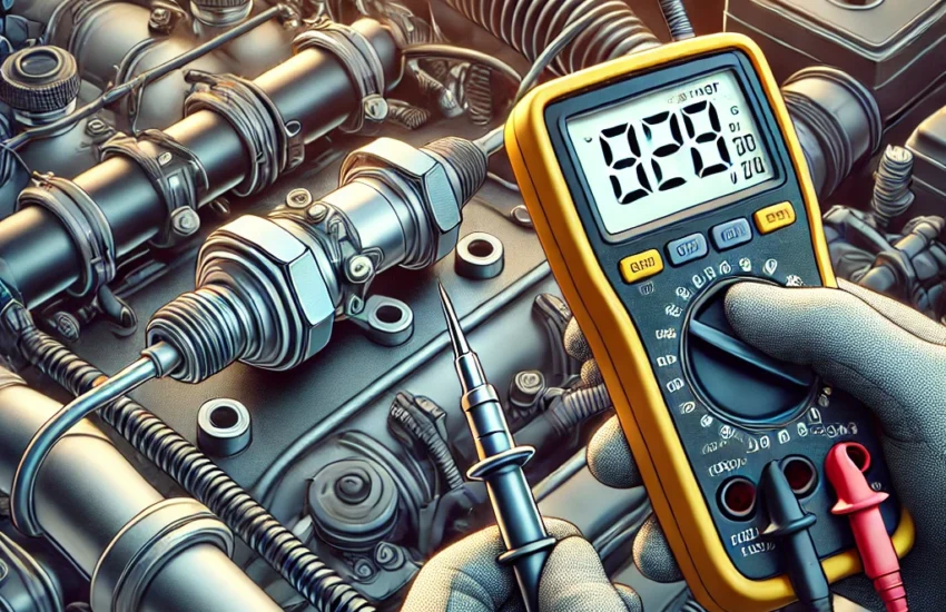
- Digital multimeter
- Protective gloves (optional)
- OBD-II scanner (optional but useful for reading error codes)
- Vehicle repair manual (to identify the correct wires)
✅ Step 1: Locate the Oxygen Sensor
Vehicles typically have one or more oxygen sensors, located:
- Before the catalytic converter (upstream sensor, O2 sensor 1)
- After the catalytic converter (downstream sensor, O2 sensor 2)
🔎 Check your car’s manual to identify their exact location.
✅ Step 2: Checking the Sensor Heater
Some oxygen sensors are heated (3, 4, or 5-wire sensors). The heater is powered by 12V and helps the sensor reach its operating temperature quickly.
- Turn the ignition on (without starting the engine)
- Set the multimeter to the DC Volts position (20V)
- Place the red probe on the heater power wire (often red/white)
- Place the black probe on a ground (chassis or negative battery terminal)
- You should read between 12V and 14V.
📌 If no voltage is present, check the sensor fuses and wiring.
✅ Step 3: Testing the Heater Resistance
- Disconnect the oxygen sensor
- Set the multimeter to the Ohms (Ω) position
- Place the probes on the two heater wires (often white and white)
- The normal value is between 5Ω and 20Ω (depending on the manufacturer)
📌 If the resistance is infinite (OL on the multimeter), the heater is broken and the sensor is faulty.
✅ Step 4: Testing the Oxygen Sensor Signal
- Start the engine and let it warm up for 5 minutes
- Set the multimeter to DC Volts (2V or 2000mV)
- Place the red probe on the sensor signal wire (usually black or gray)
- Place the black probe on a ground
Expected values for a sensor in good condition:
- Engine idling: The voltage should oscillate between 0.1V and 0.9V
- Rapid acceleration: The voltage should rise towards 0.9V
- Deceleration: The voltage should drop towards 0.1V
📌 If the voltage is fixed or does not vary rapidly, the sensor is likely faulty.
✅ Step 5: Verification with an OBD-II Scanner (Optional)
If you have an OBD-II scanner, you can check the error codes and real-time values of the O2 sensor.
- P0131 to P0139: Problems related to O2 sensors
- P0420 / P0430: Catalyst system efficiency below threshold (related to oxygen sensors)
📌 Conclusion
🔹 If the sensor does not respond or shows abnormal values, it is likely faulty and must be replaced.
🔹 If the heater resistance is infinite, the sensor heater is broken and it needs to be changed.
🔹 A faulty oxygen sensor leads to poor combustion, excessive fuel consumption, and reduced performance.