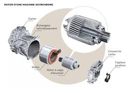
Electric motors are at the heart of industrial systems, electric vehicles, robots, and many household applications. To ensure their efficiency and precise control, it is essential to know the instantaneous position of the rotor (the rotating part of the motor). This is where the rotor position sensor comes in, a key device that provides critical information to electronic control systems. This article explores in detail the operating principles, available technologies, and practical applications of these sensors.
Role of the Rotor Position Sensor
The rotor position sensor has two main functions:
- Switching Control: In brushless motors, the electronic controller must synchronize the switching of currents in the stator windings with the rotor position to generate optimal torque.
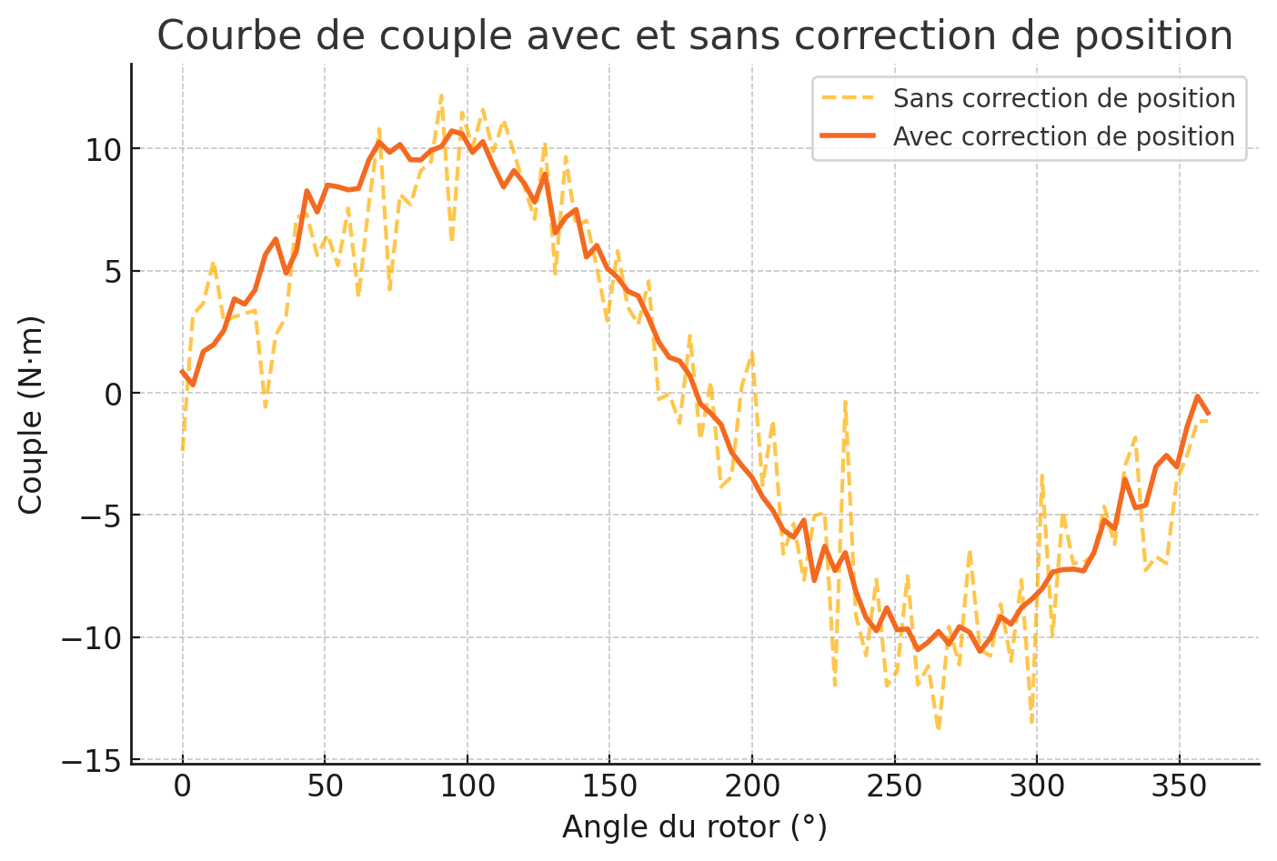
- Position Servoing: In systems requiring precise positioning (robots, CNC), the sensor enables real-time tracking and correction of the rotor’s angular position.
Without this information, the motor could lose efficiency, vibrate excessively, or even malfunction.
Position Sensor Technologies
Several technologies coexist for measuring rotor position, each with its advantages and disadvantages.
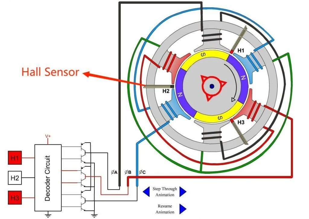
1. Hall Effect Sensors
- Principle: Hall effect sensors detect variations in the magnetic field generated by permanent magnets attached to the rotor.
- Implementation: Three Hall sensors (offset by 120°) are often used to determine position in three-phase motors.
- Advantages: Low cost, simple integration.
- Disadvantages: Limited resolution (angular accuracy of a few degrees), sensitivity to magnetic interference.
2. Resolvers
- Principle: A resolver is a rotary transformer that uses primary and secondary windings to measure angle via sinusoidal signals.
- Implementation: The rotor carries a winding excited by an AC signal, while the stator has two windings offset by 90°.
- Advantages: Robustness (resistant to vibration, extreme temperatures, and harsh environments), high reliability.
- Disadvantages: High cost, need for dedicated electronics to decode the signals.
3. Optical Encoders
- Types:
- Incremental Encoder: Generates pulses proportional to movement, requiring a zero reference.
- Absolute Encoder: Provides a unique position over 360°, even after a power outage.
- Principle: A coded disk attached to the rotor interrupts or reflects a light beam (LED/laser) to generate signals.
- Advantages: High precision (up to 0.001°), fast response.
- Disadvantages: Sensitivity to dust, moisture, and mechanical shocks.
4. Inductive Sensors (LVDT, VRS)
- Principle: Based on the variation of inductance or reluctance depending on the rotor position.
- Example: The Variable Reluctance Sensor (VRS) uses metal teeth on the rotor to alter the magnetic flux in a coil.
- Advantages: Durability, suitable for harsh environments.
- Disadvantages: Medium resolution.
Technology Comparison
| Technology | Precision | Robustness | Cost | Typical Applications |
|---|---|---|---|---|
| Hall Effect | Low | Medium | Low | Low-end motors, drones |
| Resolver | Medium | Very High | High | Aviation, electric vehicles |
| Optical Encoder | Very High | Low | Medium-High | Robots, CNC machine tools |
| Inductive Sensor | Medium | High | Medium | Heavy industry, industrial motors |
Integration into Control Systems
The sensor data is processed by an electronic motor controller (ECU) which adjusts the stator currents via an inverter (DC/AC converter). For example:
- In an electric vehicle, the controller uses the rotor position to optimize torque and speed while minimizing energy consumption.
- In robotics, absolute encoders allow precise repositioning after shutdown.
Challenges and Innovations
- Harsh Environments: Sensors must withstand extreme temperatures (-40°C to 150°C), vibrations, and EMI (electromagnetic interference).
- Miniaturization: The automotive industry demands compact sensors for integration into high-density motors.
- Sensorless Solutions: Some algorithms (flux observers, high-frequency injection) estimate position without a physical sensor, reducing costs. However, these methods remain less accurate at low speeds.
Key Applications
- Electric Vehicles: Resolvers and encoders ensure precise control of the traction motor (e.g., Tesla, BMW i3).
- Aeronautics: Resolvers used in electric flight control systems.
- Industry 4.0: Synchronous motors paired with encoders for collaborative robotics.
- Renewable Energy: Blade positioning in wind turbines.
Future Perspectives
Position sensors are evolving towards:
- Digital interfaces (SPI, CAN FD) for faster communication.
- AI integration to predict wear and optimize maintenance.
- Hybrid sensors combining Hall effect and inertial measurements (IMU) for redundancy.
Conclusion
The rotor position sensor is an indispensable component for fully harnessing the performance of modern electric motors. As demands for precision and reliability increase, technological innovations continue to push the boundaries, enabling ever more ambitious applications in a world transitioning towards electrification and automation.