The Electric Era Officially Begins for an Icon
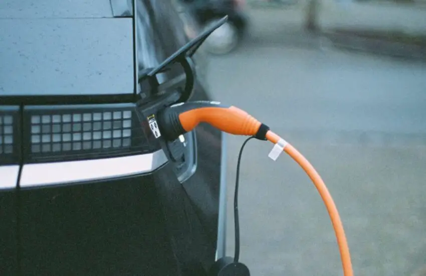
The automotive world is shifting, and one of its most enduring icons is leading the charge. Volkswagen has confirmed that the next-generation Golf, the ninth iteration, will transition to a fully electric powertrain. This monumental decision marks the end of an era for the internal combustion engine Golf and a bold step into the brand’s electric future, aligning with its broader global strategy.
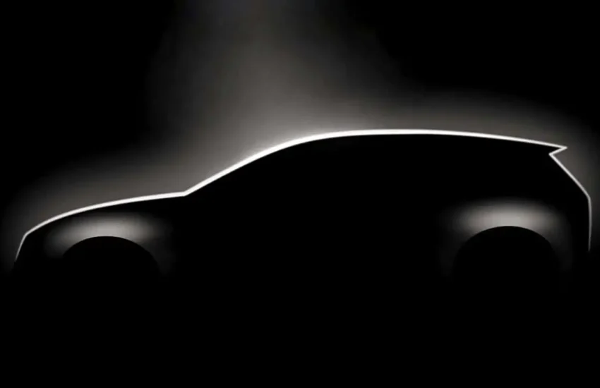
Design Sketches Hint at an Evolutionary Leap
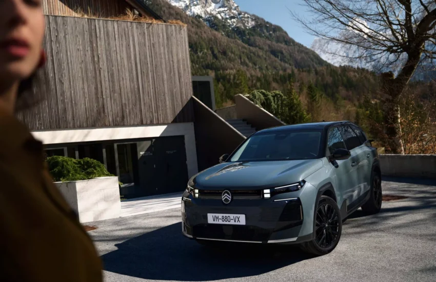
Recently released preliminary sketches provide the first concrete look at the Golf 9’s direction. While clearly retaining the familiar, practical hatchback silhouette that has defined the model for decades, the design incorporates sharper, more aerodynamic lines and a reinterpreted front end, likely devoid of a traditional grille. The sketches suggest a vehicle that honors its heritage while fully embracing a modern, EV-specific identity, promising improved efficiency and a distinctive road presence.
Understanding the Production Timeline
Prospective buyers should prepare for a waiting game. Industry reports indicate that the all-electric Volkswagen Golf 9 is not expected to enter production until late 2027 or even 2028. This extended timeline is attributed to the development of Volkswagen’s new, scalable electric platform designed for compact vehicles, which will underpin this crucial model. The delay underscores the complexity of engineering a high-volume EV that must meet the Golf’s legendary standards for quality, dynamics, and value.
What This Means for the Market
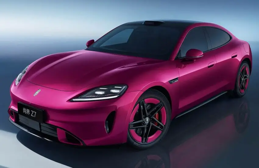
The electrification of the Volkswagen Golf is more than just a model update; it’s a signal to the entire compact car segment. By committing its best-seller to a zero-emission future, Volkswagen is accelerating the mainstream adoption of EVs. The Golf 9 EV will enter a increasingly competitive field, challenging rivals and setting new benchmarks for what consumers can expect from an electric compact car in terms of practicality, driving enjoyment, and everyday usability.